1
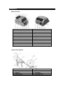
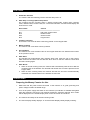
Money Counter
SPECIFICATIONS
Counting Speed
Banknote Sizes
Banknote Thickness
Hopper Capacity
Display
Alarm Display
Batch Display
Environmental Temperature
Moisture
Power Source
Power Consumption
Net Weight
Gross Weight
>1000 pcs.
100 mm x 50 mm to 173 mm x 85 mm
0.075 mm to 0.015 mm
130 pcs.
LED 999
1 LED Display
3 LED Display
0°C to 40°C
30% to 90 %
110 V, 60 Hz; 220 V, 50 Hz
<70 Watts (in operation)
<10 Watts (when not in operation)
6.5 Kg
7.0 Kg
Illustrations
Money Counter
1 – Hopper Plate
2 – Preset (Batch) Display
3 – Alarm Display
4 – Count Display
5 – +1 Key
6 – x10 Key
7 – Preset (Batch) Key
8 – Clear and Reset Key
9 – UV Key
10 – ADD Key (Accumulation)
11 – Stacker Plate
12 – Stacker Sensor
13 – Stacker Vanes
14 – UV Indicator
15 – ADD Indicator
16 – Handle
17 – Hopper Sensor
18 – Rear Cover Screw
19 – Hopper Adjust Screws
20 – Power Switch
21 – Fuse
22 – External Displayer Socket
23 – Power Socket
24 – UV Sensitive Adjuster (UV Type)
Hopper Plate System
1 – Hopper Plate
2 – Plate String
3 – Resistance Rubber
4 – Adjusters
5 – Adjuster Spring
6 – Hopper Sensor
7 – Bottom Plate
8 – 5 x 5 Pin
9 – Feed Roller
10 – Feed Roller Core
FEATURES
1.
Automatic Self-Test
The machine will automatically perform self–test after power on.
2.
Auto-Stop on Foreign (Abnormal) Notes
The machine will stop counting when it detects forged notes, foreign notes, jammed
notes, doubled notes, broken notes, etc. The buzzer will alarm and the Preset Display will
show the error code.
Error Codes
Causes
--------------------------------------------------------------------------------EC1
Half notes, broken notes
EC2
Doubled notes
EC3
Chained notes
EC4
Forged notes
3.
Common Counting
The machine can count all bank notes being placed on the Hopper Plate.
4.
Batch Counting
The machine can count bank notes by batches.
5.
Accumulation
The machine can count all bank notes on the Hopper Plate and can add the total number
to the previous counts.
6.
Auto–Start
The machine will automatically start counting when bank notes are put on the Hopper
Plate. Remove the notes from the Stacker when done so that the machine could reset
and start counting again.
7.
Auto–Reset
a. When in normal counting mode, the machine will automatically clear the sum after the
counted notes on the Stacker are removed and another set of notes is placed into the
Hopper Plate.
b. When in batch counting mode, the machine will clear the sum and will automatically
reset after the counted notes on the Stacker are removed.
OPERATIONS
Preparing the Money Counter for Use
1.
Make sure that the power socket connected to the machine is in good grounding and
power voltage is within the stated range.
2.
Turn on the power supply and switch on the machine (UV indicator is enabled and lighted
when the machine is turned on). The machine will then do automatic self–test. Error codes
will be displayed on the Preset Display when errors have been encountered.
3.
The machine is initially set to Normal Counting mode.
4.
The Count Display initially displays “0” and the Preset Display initially displays nothing.
Panel Key Functions
1.
UV Key
Press this key to enable or disable fluorescence test. The UV indicator will be lighted if
this function is enabled; otherwise this indicator is switched off.
2.
Preset Key
Press this key to clear Preset Display and to set the machine to Normal Counting mode.
3.
Clear and Reset Key
Press this key to clear and reset values.
4.
ADD Key
Press this key to set the machine to Add or Accumulating mode.
5.
6.
+1 Key
x10 Key
Press these keys to set batch number. The batch number should be in the range of 1 to
999.
Caution:
The panel keys should not be pressed when the machine is counting notes. Pressing any
keys while note counting is in progress could cause jamming or output problems.
Counting Modes
1.
Normal Counting Mode
Press the Preset key to clear Preset Display and set the machine to normal counting
mode. Put bank notes on the Hopper Plate and these will be automatically counted.
Results will be shown on the Count Display. To count another set of bank notes, remove
the counted bank notes and put a new set on the Hopper Plate. The machine will not start
counting unless the counted notes are removed.
2.
Batch Counting Mode
Press the Preset key to clear Preset Display. Set the batch number (number of bank
notes to count) using +1 and x10 keys. The batch number must be between 1 and 999.
After setting the batch number, put bank notes on the Hopper Plate and the machine will
automatically start counting by batch. It will automatically stop counting when the preset
batch number is reached. Remove the counted bank notes to start counting another
batch. Put more bank notes on the Hopper Plate if the current bank notes are insufficient.
The preset batch number will be overwritten each time you set a new number for batch
counting.
3.
Accumulation
Press Add key to set the machine to accumulating mode and add the count to the next
count of bank notes. The Add indicator will be lighted. Put bank notes to be counted on
the Hopper Plate and then, the machine will automatically start counting this set of notes.
After counting, put another set of bank notes on the Hopper Plate. The current count of
bank notes is added to the previous count and displayed on the Count Display.
MISCELLANEOUS
Adjustments on the Hopper Plate
Caution:
Switch off the machine and disconnect the power cable from the plug before checking the
Hopper Plate.
Adjusting the Hopper System
Adjust the Hopper Adjust Screws.
Changing the Resistance Rubber
When the Resistance Rubber got worn out, follow these steps to replace it:
1. Remove the Hopper Plate Screw and the Hopper Springs.
2. Replace it with the spare rubber attached in the package.
Adjusting the Plate Spring
The Plate Spring should be 10mm – 12mm away from the Resistance Rubber. If the
distance is too short, bank notes can not be separated smoothly, and if the distance
is too long, bank notes can not go down easily.
After making the necessary adjustments, switch on the machine. Test the system using
one piece of note. With one end in your hand, let the other end go vertically to the Feed
Rollers. You should feel a balanced tension on both sides of the rollers. The gap between
the Hopper Plate and the Feed Rollers can be adjusted by the Hopper Adjust Screws.
Turn clockwise to tighten the gap or turn it counter clockwise to loosen it.
Troubleshooting
Error Signals
ER0
Descriptions
- Left Counting Sensor is covered with dust
- Left Counting Sensor is not positioned well
- Left Counting Sensor is broken
ER1
- Right Counting Sensor is covered with dust
- Right Counting Sensor is not positioned
well
- Right Counting Sensor is broken
ER2
- Hopper Sensor is covered with dust
- Hopper Sensor is not positioned well
- Hopper Sensor is broken
ER3
- Stacker Sensor is covered with dust
- Stacker Sensor is not positioned well
- Stacker Sensor is broken
ER4
(UV models
only)
ER8
- UV Sensor is covered with dust
- UV Sensor is broken
- Width Detection Sensor does not have
enough voltage
- Width Detection Sensor is broken
Solutions
- Clean the Left Counting
Sensor
- Reposition the Left Counting
Sensor
- Replace the Left Counting
Sensor with a new one
- Clean the Right Counting
Sensor
- Reposition the Right Counting
Sensor
- Replace the Right Counting
Sensor with a new one
- Clean the Hopper Sensor
- Reposition the Hopper Sensor
- Replace the Hopper Sensor
with a new one
- Clean the Stacker Sensor
- Reposition the Stacker Sensor
- Replace the Stacker Sensor
with a new one
- Clean the UV Sensor
- Replace the UV Sensor with a
new one
- Adjust the voltage
- Replace the Width Detection
Sensor with a new one