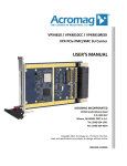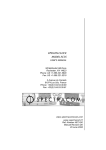
1
TSync-PCIe PCI EXPRESS TIME CODE PROCESSOR with OPTIONAL GPS and TSync-PCIe-PTP User Manual 95 Methodist Hill Drive Rochester, NY 14623 Phone: US +1.585.321.5800 Fax: US +1.585.321.5219 www.spectracomcorp.com Part Number 1191-5000-0050 Manual Revision E January 2011 Copyright © 2011 Spectracom Corporation. The contents of this publication may not be reproduced in any form without the written permission of Spectracom Corporation. Printed in USA. Specifications subject to change or improvement without notice. Spectracom, NetClock, Ageless, TimeGuard, TimeBurst, TimeTap, LineTap, MultiTap, VersaTap, and Legally Traceable Time are Spectracom registered trademarks. All other products are identified by trademarks of their respective companies or organizations. All rights reserved. SPECTRACOM LIMITED WARRANTY LIMITED WARRANTY Spectracom warrants each new product manufactured and sold by it to be free from defects in software, material, workmanship, and construction, except for batteries, fuses, or other material normally consumed in operation that may be contained therein AND AS NOTED BELOW, for five years after shipment to the original purchaser (which period is referred to as the “warranty period”). This warranty shall not apply if the product is used contrary to the instructions in its manual or is otherwise subjected to misuse, abnormal operations, accident, lightning or transient surge, repairs or modifications not performed by Spectracom. The GPS receiver is warranted for one year from date of shipment and subject to the exceptions listed above. The power adaptor, if supplied, is warranted for one year from date of shipment and subject to the exceptions listed above. THE ANALOG CLOCKS ARE WARRANTED FOR ONE YEAR FROM DATE OF SHIPMENT AND SUBJECT TO THE EXCEPTIONS LISTED ABOVE. THE TIMECODE READER/GENERATORS ARE WARRANTED FOR ONE YEAR FROM DATE OF SHIPMENT AND SUBJECT TO THE EXCEPTIONS LISTED ABOVE. The Rubidium oscillator, if supplied, is warranted for two years from date of shipment and subject to the exceptions listed above. All other items and pieces of equipment not specified above, including the antenna unit, antenna surge suppressor and antenna pre-amplifier are warranted for 5 years, subject to the exceptions listed above. WARRANTY CLAIMS Spectracom’s obligation under this warranty is limited to in-factory service and repair, at Spectracom’s option, of the product or the component thereof, which is found to be defective. If in Spectracom’s judgment the defective condition in a Spectracom product is for a cause listed above for which Spectracom is not responsible, Spectracom will make the repairs or replacement of components and charge its then current price, which buyer agrees to pay. Spectracom shall not have any warranty obligations if the procedure for warranty claims is not followed. Users must notify Spectracom of the claim with full information as to the claimed defect. Spectracom products shall not be returned unless a return authorization number is issued by Spectracom. Spectracom products must be returned with the description of the claimed defect and identification of the individual to be contacted if additional information is needed. Spectracom products must be returned properly packed with transportation charges prepaid. Shipping expense: Expenses incurred for shipping Spectracom products to and from Spectracom (including international customs fees) shall be paid for by the customer, with the following exception. For customers located within the United States, any product repaired by Spectracom under a “warranty repair” will be shipped back to the customer at Spectracom’s expense unless special/faster delivery is requested by customer. Spectracom highly recommends that prior to returning equipment for service work, our technical support department be contacted to provide trouble shooting assistance while the equipment is still installed. If equipment is returned without first contacting the support department and “no problems are found” during the repair work, an evaluation fee may be charged. EXCEPT FOR THE LIMITED WARRANTY STATED ABOVE, SPECTRACOM DISCLAIMS ALL WARRANTIES OF ANY KIND WITH REGARD TO SPECTRACOM PRODUCTS OR OTHER MATERIALS PROVIDED BY SPECTRACOM, INCLUDING WITHOUT LIMITATION ANY IMPLIED WARRANTY OR MERCHANTABILITY OR FITNESS FOR A PARTICULAR PURPOSE. Spectracom shall have no liability or responsibility to the original customer or any other party with respect to any liability, loss, or damage caused directly or indirectly by any Spectracom product, material, or software sold or provided by Spectracom, replacement parts or units, or services provided, including but not limited to any interruption of service, excess charges resulting from malfunctions of hardware or software, loss of business or anticipatory profits resulting from the use or operation of the Spectracom product or software, whatsoever or howsoever caused. In no event shall Spectracom be liable for any direct, indirect, special or consequential damages whether the claims are grounded in contract, tort (including negligence), or strict liability. EXTENDED WARRANTY COVERAGE Extended warranties can be purchased for additional periods beyond the standard five-year warranty. Contact Spectracom no later than the last year of the standard five-year warranty for extended coverage. SPECTRACOM 95 Methodist Hill Drive Rochester, NY 14623 +1.585.321.5800 FAX: +1.585.321.5218 www.spectracomcorp.com [email protected] This equipment has been tested and found to comply with the limits for a Class A digital device, pursuant to Part 15 of the FCC Rules. These limits are designed to provide reasonable protection against harmful interference when the equipment is operated in a commercial environment. This equipment generates, uses, and can radiate radio frequency energy and, if not installed and used in accordance with the instruction manual, may cause harmful interference to radio communications. Operation of this equipment in a residential area is likely to cause harmful interference in which case the user will be required to correct the interference at his own expense. TSync-PCIe 1 1.1 1.2 1.3 1.4 2 2.1 2.2 2.3 2.4 2.5 2.6 2.7 2.8 2.9 2.10 2.11 2.11.1 2.12 2.12.1 2.12.2 2.12.3 2.13 2.14 2.15 3 3.1.1 4 4.1 4.2 4.3 5 5.1 5.1.1 5.1.2 5.1.3 5.1.4 5.1.5 5.2 5.3 5.4 5.4.1 5.4.2 5.4.3 5.4.4 5.5 5.5.1 5.5.2 5.6 Spectracom Corporation Table of Contents OVERVIEW ............................................................................................................... 1-1 General Information about GPS................................................................................................................... 1-1 Your Spectracom GPS Receiver ................................................................................................................. 1-2 Inventory ...................................................................................................................................................... 1-2 Inspection and Support ................................................................................................................................ 1-2 SPECIFICATIONS ....................................................................................................... 2-1 PCIe Power.................................................................................................................................................. 2-1 IRIG AM Input .............................................................................................................................................. 2-1 IRIG DCLS Input .......................................................................................................................................... 2-1 IRIG AM Output ........................................................................................................................................... 2-1 IRIG DCLS Output ....................................................................................................................................... 2-2 10MHz Output.............................................................................................................................................. 2-2 External 1PPS Input .................................................................................................................................... 2-2 1PPS Output ................................................................................................................................................ 2-3 GPIO Inputs ................................................................................................................................................. 2-3 GPIO Outputs .............................................................................................................................................. 2-3 On-Board GPS RF Connector (Internal GPS Receiver) .............................................................................. 2-3 Electrical Characteristics, GPS RF Signal ................................................................................................... 2-3 External GPS Connector (External GPS Receiver) ..................................................................................... 2-3 Electrical Characteristics (Transmitted from Board to Receiver) ................................................................. 2-3 Electrical Characteristics (Transmitted from Receiver to Board) ................................................................. 2-4 Electrical Characteristics (Receiver Power) ................................................................................................. 2-4 GPS Receiver Specifications (Internal and External GPS Receivers) ......................................................... 2-4 PTP Interface (TSync-PCIe-PTP Only)........................................................................................................ 2-4 Environmental Specifications ....................................................................................................................... 2-4 PINOUTS .................................................................................................................. 3-1 Timing Connector Pinout ............................................................................................................................. 3-1 INSTALLATION .......................................................................................................... 4-1 GPS Receiver/Antenna (Internal and External GPS Receivers) .................................................................. 4-1 Changing the Board Bracket (Not Applicable to TSync-PCIe-PTP) ............................................................. 4-2 Installing the Board in the Computer............................................................................................................ 4-4 THEORY OF OPERATION............................................................................................ 5-1 Input References ......................................................................................................................................... 5-1 GPS Receivers as Input References ........................................................................................................... 5-1 IRIG Inputs................................................................................................................................................... 5-1 External 1PPS Reference ............................................................................................................................ 5-3 PTP Reference ............................................................................................................................................ 5-3 Built-in References ...................................................................................................................................... 5-3 Input Reference Monitor .............................................................................................................................. 5-4 Clock Subsystem ......................................................................................................................................... 5-4 Output References....................................................................................................................................... 5-5 IRIG Output.................................................................................................................................................. 5-5 10MHz Sine Wave Output ........................................................................................................................... 5-6 1PPS Output ................................................................................................................................................ 5-6 PTP Output .................................................................................................................................................. 5-7 General Purpose Input/Output ..................................................................................................................... 5-7 Programmable Inputs .................................................................................................................................. 5-7 Programmable Outputs................................................................................................................................ 5-7 System Status.............................................................................................................................................. 5-8 PCI Express Time Code Processor User Manual iii Spectracom Corporation 5.7 5.8 5.9 5.9.1 6 6.1 6.2 6.2.1 6.2.2 6.2.3 7 iv TSync-PCIe LEDs ............................................................................................................................................................ 5-8 Upgrade ....................................................................................................................................................... 5-8 Interrupts...................................................................................................................................................... 5-8 Interrupt Descriptions................................................................................................................................... 5-8 OPTIONS AND ACCESSORIES .................................................................................... 6-1 Options ........................................................................................................................................................ 6-1 Accessories ................................................................................................................................................. 6-1 Premium Breakout Cable............................................................................................................................. 6-1 Basic Breakout Cable .................................................................................................................................. 6-2 GPS Cables ................................................................................................................................................. 6-2 DRIVER SUPPORT ...................................................................................................... 7-1 PCI Express Time Code Processor User Manual TSync-PCIe Spectracom Corporation 1 Overview The TSync-PCIe with optional GPS is a complete synchronized timecode reader/generator package that supports multiple prioritized timing inputs. When an input is lost, the unit automatically switches to the next input in order of priority. The disciplined onboard oscillator is phase-locked to an external timing input, providing 5ns resolution time. This 10 MHz oscillator, central to the TSync-PCIe timing functions, uses the last known reference to increment (“freewheel”) in the absence of a timing input. The TSync-PCIe generates an IRIG AM and DCLS output pair, as well as 10 MHz sine wave and 1PPS outputs. The board’s four programmable inputs may be used as event capture inputs, dedicated to your time-tagging applications. Four user-programmable alarm and frequency outputs are also provided. Programmable output functions include a periodic pulse or “heartbeat,” square wave, and programmable start/stop time “alarm” output. Key to the TSync functionality is the ability to generate interrupts. Using one of the many available Spectracom driver packages, you may configure your card using interrupt-driven algorithms to support your unique applications. The TSync-PCIe-PTP includes all the synchronization features of the TSync-PCI, and can also interface with PTP timing networks as a Master or a Slave. 1.1 General Information about GPS The United States government operates a set of approximately 32 satellites, collectively known as the "GPS Constellation" or "GPS Satellites." Each satellite has an internal atomic clock and transmits a signal specifying the time and satellite position. On the ground, the GPS receiver determines its position (longitude, latitude, and elevation) and the time by decoding the signals simultaneously from at least four of the GPS satellites. The satellite orbits are circular, inclined approximately 56 degrees from the equator, orbiting the Earth once every 11 hours. There are several different orbital planes, providing continuous coverage to all places on Earth. The GPS receiver uses an omni-directional antenna; the satellites move slowly across the sky (they are not at fixed locations). Each satellite transmits a spread-spectrum signal, centered at 1575.42 MHz. When power is first applied, the GPS receiver begins searching for the satellites. It does this by searching for each satellite individually, listening for each satellite's distinct spread-spectrum hopping sequence. This process can take a few minutes, as the receiver iteratively locates satellites, refines its position, and determines for which satellites to search. The GPS receiver retains the last known position when the power is switched off. This results in faster satellite acquisition the next time it is switched on. If the antenna has been moved more than a few miles, however, acquisition time will be slightly longer because it must first recompute the position. PCI Express Time Code Processor User Manual 1-1 Spectracom Corporation TSync-PCIe 1.2 Your Spectracom GPS Receiver Your board’s GPS receiver is either internal (mounted to the unit) or external. In the case of the internal receiver, the board supplies 5VDC to the connected external antenna, which is necessary for GPS operation. In the case of the external receiver, which is built into an external antenna housing of its own, the receiver communicates with the board via a serial (RS-422) interface. Power (+12V) is supplied from the board. NOTE: Spectracom recommends applying an appropriate silicon grease to the cable connection at the external GPS receiver antenna in order to protect the connection from moisture. An additional weatherproofing kit (P/N 221213) containing butyl rubber and plastic tape is also available from Andrews Corporation, US 800.255.1479. 1.3 Inventory Before installing the board, please verify that all material ordered has been received. All boards are shipped with a break-out cable and a user manual. TSync-PCIe boards include a full-height bracket (the board is attached to a half-height bracket as shipped). TSync-PCIe-PTP boards can only be used in full-height PCIe slots. Boards equipped with internal GPS receivers are shipped with an SMA to Type N RF adapter cable. Boards equipped with an external GPS receiver are shipped with a 100-foot antenna cable and a mini-DIN to DB-15 adapter cable. Extension cables for the external GPS receiver are available in 100-foot lengths. The maximum total length is 500 feet. The connectors on the extension cables are not weatherproof; only the first 100-feet can be outdoors. The cable consists of several twisted pairs (not coaxial cable) and a foil shield. If there is any discrepancy between items ordered and items shipped and received, please contact Spectracom Customer Service at US +1.585.321.5800. 1.4 Inspection and Support Unpack the equipment and inspect it for damage. If any equipment has been damaged in transit, please contact Spectracom Customer Service at US +1.585.321.5800. If any problems occur during installation and configuration of your Spectracom product, please contact Spectracom Technical Support at US 585.321.5823 or US 585.321.5824. 1-2 PCI Express Time Code Processor User Manual CAUTION: Electronic equipment is sensitive to Electrostatic Discharge (ESD). Observe all ESD precautions and safeguards when handling the timecode generator. NOTE: If equipment is returned to Spectracom, it must be shipped in its original packing material. Save all packaging material for this purpose. PCI Express Time Code Processor User Manual 1-3 TSync-PCIe Spectracom Corporation 2 Specifications 2.1 PCIe Power • • +3.3V ±5%, 0.7A typical +12V ±8%, 0.2A typical 2.2 IRIG AM Input • • • • • • IRIG AM Input at timing interface connector Accepts IRIG Formats A, B, G; NASA36; IEEE 1344 Amplitude o 500mVp-p to 10Vp-p Modulation Ratio o 2:1 minimum, 7:1 maximum Input Impedance o 10k-ohm minimum DC Common Mode Voltage o +/- 150VDC maximum 2.3 IRIG DCLS Input • • • • IRIG DCLS Input at timing interface connector Accepts IRIG formats A, B, G; NASA36; IEEE 1344 pulse width codes (does not accept Manchester modulated codes) RS-485 Differential Input o -7V – +12V common mode voltage input range, 200mVp-p differential voltage threshold Single Ended Input o +1.3V VIL min, +2V VIH max o +1.45V VIL typ, +1.85V VIH typ 2.4 IRIG AM Output • • • • • • IRIG AM output at timing interface connector Outputs formats A, B, E(100Hz, 1KHz), G; NASA36; IEEE 1344 Amplitude o 0.5Vp-p to 6Vp-p into 50 ohms, user settable o 1Vp-p to 12Vp-p into > 600 ohms Output Impedance o 50 ohm nominal Output load o 50 ohm minimum Modulation Ratio o 3.3:1 nominal PCI Express Time Code Processor User Manual 2-1 Spectracom Corporation TSync-PCIe 2.5 IRIG DCLS Output • • • IRIG DCLS output at timing interface connector Outputs formats A, B, E, G; NASA36; IEEE 1344 pulse width codes (does not generate Manchester modulated codes) RS-485 Differential Signal o +1.5V +2V Common Mode Output Voltage, o 1.5V min to 3.3V max Differential Output Voltage Swing 2.6 10MHz Output • • • • • • • • 10MHz Sine Wave output from Oscillator Amplitude o 12 dBm(2.5Vp-p), nominal into 50 ohm, +/-3dB, o 5Vp-p nominal into high impedance, +/-3dB, Output Impedance o 50 ohm nominal Output Load o 50 Ohms minimum Output Harmonics o < -40 dBc Output Spurious o < -60 dBc Free run Stability o TCXO +/- 1PPM, -40C to 85C o OCXO +/- 50PPB, -40C to 85C Output Phase Noise (25C Ambient) o TCXO -110 dBc/Hz > 100 Hz -135 dBc/Hz > 1 kHz -140 dBc/Hz > 10 kHz o OCXO -85 dBc/Hz > 1Hz -110 dBc/Hz > 10 Hz -120 dBc/Hz > 100 Hz -140 dBc/Hz > 1 kHz -150 dBc/Hz > 10 kHz -150 dBc/Hz > 100 kHz 2.7 External 1PPS Input • • • • 2-2 External 1PPS reference input to timing connector 1Hz Pulse, Rising Edge or Falling Edge Active (selectable) o 1 usec. minimum pulse width 0V – +5.5V Input Range, +0.8V VIL, +2.0V VIH Input Impedance <150 pF capacitive PCI Express Time Code Processor User Manual TSync-PCIe Spectracom Corporation 2.8 1PPS Output • • • 1PPS output at timing interface connector 1Hz Pulse, Rising Edge or Falling Edge Active (selectable) o 40ns - 900ms Active Pulse Width (selectable, 200ms default) +0.55V VOL, +2.2V VOH 2.9 GPIO Inputs • • • • • GPIO inputs to timing connector 50ns Active Pulse Width minimum 50ns minimum between pulses 0V – +5.5V Input Range, +0.8V VIL, +2.0V VIH Input Impedance <150 pF capacitive 2.10 GPIO Outputs • • • • GPIO outputs from timing connector Pulse Output o 20ns – 900ms Active Pulse Width Square Wave Output o 100ns – 20 second period o 20 ns – 900 ms Active Pulse Width +0.55V VOL, +2.2V VOH 2.11 On-Board GPS RF Connector (Internal GPS Receiver) The on-board GPS RF connector supports the RF connection between the on-board GPS receiver and an external L1 antenna. It consists of a female SMA connector. A short male SMA to female N cable made from RG-316 coax is provided to connect to the antenna RF cable. NOTE: The provided cable should be used instead of an adapter. This relieves strain on the connectors. 2.11.1 Electrical Characteristics, GPS RF Signal • • L1 (1575.42 MHz) GPS Signal from Antenna to On-Board GPS receiver 30mA @ +5V (±10%) provided to power antenna 2.12 External GPS Connector (External GPS Receiver) A provided mini-DIN to DB-15 adapter cable is used to connect the external antenna (with its built-in GPS receiver) to the board. 2.12.1 Electrical Characteristics (Transmitted from Board to Receiver) • RS-485 Differential Signal o +1.5V +2V Common Mode Output Voltage, o 1.5V min to 3.3V max Differential Output Voltage Swing PCI Express Time Code Processor User Manual 2-3 Spectracom Corporation TSync-PCIe 2.12.2 Electrical Characteristics (Transmitted from Receiver to Board) • RS-485 Differential Input o -7V – +12V common mode voltage input range, 200mVp-p differential voltage threshold 2.12.3 Electrical Characteristics (Receiver Power) • 50 mA @ 12 Volts provided to power antenna 2.13 GPS Receiver Specifications (Internal and External GPS Receivers) • • • • • • Acquisition Time (cold start) o <46 sec (50%), <50 sec (90%) Re-acquisition Time o <2 sec (90%) Frequency o L1 frequency, C/A code (DSP), 12-channel, parallel-tracking Sync to UTC o Within ±15 ns to GPS/UTC (1 sigma) (stationary) Accuracy Horizontal Position o <6 meters (50%) <9 meters (90%) Accuracy Altitude Position o <11 meters (50%) <18 meters (90%) 2.14 PTP Interface (TSync-PCIe-PTP Only) • • • Master or Slave Operation o IEEE 1588v2-2008 fully compliant o 10/100 Mb Ethernet, RJ45 o 8 nS (+/- 4 nS) packet timestamping resolution o 30 nS accuracy (3σ) Master to Slave via Crossover Cable o 1 step or 2 step operation Master Mode o IRIG, 1ppS, or other Time Code Input o Capacity: > 512 Syncs/sec (dependent on number of slaves) Slave Mode o Outputs IRIG Time codes, frequency, and general purpose outputs and events tagging 2.15 Environmental Specifications • • • 2-4 Temperature o Operating: o Storage: Humidity o Operating and Storage: Altitude o Operating: o Storage: -40° C to 75° C -40° C to 85° C 5% to 95% RH, non-condensing Up to 10,000 feet Supports commercial shipping altitudes PCI Express Time Code Processor User Manual TSync-PCIe PCI Express Time Code Processor User Manual Spectracom Corporation 2-5 TSync-PCIe Spectracom Corporation 3 Pinouts The pinouts for the TSync-PCIe are as follows: RED LED YELLOW LED GREEN LED 25-PIN CONNECTOR GPS CONNECTOR (On-Board GPS Connector shown) The timing interface connector supports all of the input and output references, and GPIO. It consists of a 25-pin micro-miniature D-sub plug. 3.1.1 Timing Connector Pinout Table 3.1—Pinout Pin Signal 1 GPIO Output 2 2 Ground 3 GPIO Output 0 4 GPIO Input 2 5 Ground 6 GPIO Input 0 7 External 1PPS Input 8 Ground 9 IRIG AM Output 10 IRIG AM Input + 11 IRIG AM Input 12 IRIG DCLS Output 13 IRIG DCLS Output + PCI Express Time Code Processor User Manual Pin 14 15 16 17 18 19 20 21 22 23 24 25 Signal GPIO Output 3 Ground GPIO Output 1 GPIO Input 3 Ground GPIO Input 1 1PPS Output Ground 10MHz Output Ground IRIG DCLS Input IRIG DCLS Input + 3-1 Spectracom Corporation 3-2 TSync-PCIe PCI Express Time Code Processor User Manual TSync-PCIe Spectracom Corporation 4 Installation 4.1 GPS Receiver/Antenna (Internal and External GPS Receivers) The mounting location should be free of objects that could obstruct satellite visibility from straight overhead to within 20 degrees of the horizon in all directions. Obstructions that block a significant portion of the sky result in degraded performance. Specifically, the GPS receiver can track fewer than four satellites, which would prevent it from obtaining time synchronization. To optimize timing accuracy, the GPS receiver attempts to track satellites that are spread out as far as possible across the sky. The GPS receiver/antenna must be mounted with the connector side pointing down and must be spaced at least 39 inches (1 meter) away from other GPS antennas. Mount the antenna at the desired location. Connect the supplied cable to the antenna. Take appropriate lightning precautions as necessary. NOTE: Spectracom recommends applying an appropriate silicon grease to the cable connection at the GPS antenna in order to protect the connection from moisture. An additional weatherproofing kit (P/N 221213) containing butyl rubber and plastic tape is also available from Andrews Corporation, US 800.255.1479. NOTE: GPS receivers connected to the TSync-PCIe are reset to factory default settings during normal operation. If you are replacing an existing legacy board-level product installation, be aware of the fact that your GPS receiver will no longer operate with legacy board-level products after it operates with a TSync-PCIe. PCI Express Time Code Processor User Manual 4-1 Spectracom Corporation TSync-PCIe 4.2 Changing the Board Brack et (Not Applicable to TSync-PCIePTP) The TSync-PCIe is attached to a half-height bracket as shipped. To change this bracket, install the provided full-height bracket as follows, following all applicable ESD procedures. 1 2 4 5 3 1. Tools required for this procedure include a #1 Phillips head screwdriver, a 1/8-inch nut driver or open-end wrench, and a 5/16” driver, wrench, or socket. 2. Internal GPS receiver boards only: Using the 5/16-inch driver or wrench, remove the nut and lock washer securing the GPS RF cable to the board. Slide the cable out of the D-hole in the half-height bracket. 3. Use the Phillips-head screwdriver to remove the Phillips-head screw securing the bracket to the TSync-PCIe board. 4. Using the 1/8-inch nut driver, remove the two jack screws from the 25-pin connector. The half-height bracket can now be removed from the TSync-PCIe board. 5. Install the full-height bracket. Replace the jack screws on the 25-pin connector. NOTE: It may be desirable to install the Phillips-head screw finger-tight, then the jack screws, before completely tightening the Phillips-head screw. Also, be careful to seat the jack screws fully in the holes in the full-height bracket, or the breakout cable will not attach properly to the 25-pin connector when the cable is connected to the board for operation. 6. Reverse steps 1 through 3 in order to complete installation of the full-height bracket. Reconnect the Phillips-head screw to secure the bracket on the board and, for boards 4-2 PCI Express Time Code Processor User Manual TSync-PCIe Spectracom Corporation with internal GPS receivers, reconnect the SMA RF connector cable (being sure to align it properly in the D-hole). PCI Express Time Code Processor User Manual 4-3 Spectracom Corporation TSync-PCIe 4.3 Installing the Board in the Computer Shut the computer down, then turn its power switch off and unplug the line cord. Open the computer and install the board in any unused PCIe slot. CAUTION: Observe all ESD procedures when handling the board and the computer. Before installing the board, discharge static buildup by touching the metal frame of the computer with one hand and the protective bag containing the board with the other hand. Open the protective bag only after static buildup has been safely discharged. Remove the metal plate at the desired location on the rear panel, then plug in the board. Attach the top of the mounting bracket with the screw from the metal plate. The board is supplied with a half-height bracket installed. A full-height bracket is also provided and can be used if preferable for your application. Close the computer, plug in the line cord, and start the computer. Depending on which operating system is used, a message that identifies new hardware may appear. This message may indicate that the hardware is of "unknown type.” This is normal. Exit the "Found New Hardware" dialogue box. DO NOT click on "Have Disk." The board operates automatically as soon as the host computer system performs the power-on reset. To change the operating parameters or read data, consult the available Application Programmer’s Guide for this product. 4-4 PCI Express Time Code Processor User Manual TSync-PCIe Spectracom Corporation During start up and operation, the board LEDs flash in sequence to indicate different operational states. The patterns are as follows: State Sync Alarm Hold Over 1PPS Manual Power-On On Off Off N/A N/A Self-Test On On On N/A N/A Blink Blink Off N/A N/A Strobe Strobe Strobe N/A N/A Waiting for Host Download from Host Initialize Off Off Off - Off Never Synchronized Off Off Off - N/A Synchronized On Off Off - N/A Holdover On Off On - N/A No Longer Synchronized Off On Off - N/A Free Run Blink Off Blink - N/A • Fault Code Code Code Code Code Table 4-1: LED Flash Patterns • The code indicates the fault condition. It blinks the number of times indicated with a 2-second pause between each set. 1 Blink = FPGA programming error 2 Blinks = Failure to decompress 3 Blinks = CRC failure writing to flash 4 Blinks = Self-test failure 5 Blinks = Timing system failure NOTE: During the power-on, self-test, wait-for-host, and download-from-host states, modes are directly allocated to the LEDs (sync is green, holdover is yellow, and alarm is red). During normal operation, the user may set any LED to any of the operational modes. PCI Express Time Code Processor User Manual 4-5 TSync-PCIe Spectracom Corporation 5 Theory of Operation The TSync-PCIe architecture essentially consists of input references, which are used as sources of 1PPS synchronization and/or time-of-day (TOD) and date information, and for disciplining an internal oscillator. TSync-PCIe takes the synchronous clock, a 1PPS and time-ofday (TOD) and date to create output references that act as time references for other devices. Other interfaces for time stamping external events, creating precisely timed external signals, debug, upgrade, and access from a host computer are provided. 5.1 Input References The input references consist of multiple interfaces to various types of Time References. A Time Reference can take many forms but their fundamental responsibility is they always provide a 1PPS on-time-point, they usually provide a time-of-day and date input and they might provide a control and status protocol to the time source. The input references can also provide other time related data such as Leap Second indication and number of seconds, Julian date, day of year, day of week, week of year, status, sync indication, accuracy indication and other fields unrelated to time. The TSync-PCIe architecture’s input reference subsystem is designed to support multiple possible input references, allowing only a single time reference and 1PPS reference to discipline the local clock subsystem. The user can choose to use the factory default priority list for input references, or may define a proprietary priority list. This user priority list can be created to combine different time and 1PPS sources (such as GPS time coupled with the external 1PPS). The user is also provided with the means to enable or disable the selection of a specified input reference allowing them to disregard the list and synchronize to a specific output. 5.1.1 GPS Receivers as Input References GPS receivers are usually the highest precision and accuracy time references a TSync-PCIe board can select. GPS receivers use coaxial GPS antenna input and typically provides a serial interface and a 1PPS output. The serial interface can be used for bi-directional communication with the GPS receiver to implement a control and status protocol which conveys time and position information. 5.1.2 IRIG Inputs Inter-range instrumentation group time codes, more commonly referred to as "IRIG" time codes, were created by the Tele-Communications Working Group of the Inter-Range Instrumentation Group, which is a standard body formed by Range Commanders Council. This standard was used by US Government military test ranges, NASA, and other research organizations to distribute telemetry information, including time and frequency. The current standard version is IRIG Standard 200-4. The TSync-PCIe architecture uses IRIG formats as both input and output references. IRIG formats can be amplitude modulated, or they can be digital signals at various carrier and clock rates. The TSync-PCIe architecture supports IRIG inputs with Formats A, B, and G. It supports inputs and outputs using modulation frequency values of pulse width code, also known as DCLS (0), and sine wave amplitude modulated coding. Additionally, the board supports inputs with PCI Express Time Code Processor User Manual 5-1 Spectracom Corporation TSync-PCIe frequency/resolution values of no carrier/index count interval, 1kHz/1ms, 10kHz/0.1ms, and 100kHz/10ms, as well as IRIG input coded expressions of the fields BCDTOY, CF, SBS, and BCDYEAR. The TSync-PCIe board supports IRIG inputs of the following coded expressions combinations for BCDTOY, CF, SBS, and BCDYEAR fields: • • • • • • 0 – BCDTOY, CF, SBS 1 – BCDTOY, CF 2 – BCDTOY 3 – BCDTOY, SBS 4 - BCDTOY, BCDYEAR, CF, SBS 5 - BCDTOY, BCDYEAR, CF The TSync-PCIe supports synchronization with the following analog and DCLS IRIG input formats: A - DCLS A000 A001 A002 A003 A - AM A130 A131 A132 A133 B - DCLS B000 B001 B002 B003 B - AM B120 B121 B122 B123 G - DCLS NA G001 G002 NA G - AM NA G141 G142 NA A004 A134 B004 B124 NA NA NA NA NA NA G005 G145 Table 5-5-1 — IRIG Input Reference Formats The TSync-PCIe supports the IRIG B variant NASA36 as an input format, as well as the IEEE C37.118-2005 (which is an IRIG B format with extensions as an input format). The IEEE C37.118-2005 specification supersedes IEEE 1344-1996. The TSync-PCIe is backward compatible to IEEE 1344-1996 by compliance with IEEE C37.118-2005. The TSync-PCIe board can detect, automatically, IRIG formats A, B, G, and NASA36. IRIG format IEEE1344, coded expression, and control field information cannot be auto-detected, however. These must be specified by the user if these inputs are to be used. NOTE: Always configure IRIG parameters in the following order: format, coded expressions, control field definitions. In operation, the TSync-PCIe board receives IRIG input data and any time code messages transmitted, performs signal conditioning on the data, and decodes the data per its manually set parameters and automatically detected functions. In turn, the board provides a serial time code data message and a 1PPS reference. It also returns the IRIG input message’s raw serial time code data in Spectracom’s data format. (This is useful in debugging serial time code source and hardware implementations.) The TSync-PCIe module also accepts as input any non-standard IRIG format generated by the Spectracom Netclock, including the non-standard BCDYEAR found in the Control field. This is 5-2 PCI Express Time Code Processor User Manual TSync-PCIe Spectracom Corporation intended to support the Spectracom 91xx and 92xx IRIG formats, which use the BCDYEAR in the Control field. 5.1.3 External 1PPS Reference The board’s external 1PPS reference provides the on-time-point for the current second. This reference is used by the TSync-PCIe as the primary source of frequency synchronization (while another input reference is required to serve as the source of time and date information). The external 1PPS reference can be set to use either the rising or falling edge. 5.1.4 PTP Reference Precision Time Protocol (PTP) is a protocol that can be used to synchronize computers on a local area network. The TSync-PCIe-PTP supports PTP Version 2, as specified in the IEEE 1588-2008 standard. (PTP Version 1 is not supported). The TSync-PCIe-PTP can be configured either as a PTP Slave or a PTP Master. The TSync-PCIe-PTP can be configured as a PTP Slave which provides an input reference to the TSync-PCIe-PTP. When configured as a slave, it will synchronize to the best available master on the network. Please refer to the Driver Guide for more information about how to configure the TSync-PCIe-PTP as a slave on a PTP timing network. 5.1.5 Built-in References The TSync-PCIe board provides built-in references that support specialized user applications. 5.1.5.1 Host Reference The TSync-PCIe can be set to use the host as the source of date and time information, while another input reference is required to serve as the source of frequency input. This allows the host to provide time to the board while providing a means to determine and indicate whether that time is valid for synchronization. Using the host as a reference means it could conceivably be used to receive date and time information from a source not available to the board, providing that information to the board for synchronization to it (while using a separate frequency input). 5.1.5.2 Self Reference The TSync-PCIe provides a built-in reference that allows the board to operate without a separate input reference. The date and time or frequency information from this self reference is always considered valid. This allows a user to operate the board as if it were synchronizing to an input reference, without a valid external reference input. The self reference priority table entry defaults to “disabled.” PCI Express Time Code Processor User Manual 5-3 Spectracom Corporation TSync-PCIe 5.2 Input Reference Monitor The input reference monitor subsystem maintains the reference priority table and determines which input reference(s) are selected to synchronize the clock subsystem. Three tables are maintained by the system: • A default table, which provides the default reference pairings in timing accuracy priority • A working table, which is the table used for selecting reference inputs • A user table, which can be stored persistently and, if present, will be loaded into the working table at startup Enable en en en en en dis dis dis Priority 1 2 3 4 5 6 0 0 Time Ref gps0 ird0 ira0 hst0 hst0 self 1PPS Ref gps0 ird0 ira0 epp0 self self gps = GPS Reference, ird = IRIG DCLS Reference, ira = IRIG AM Reference, epp = External 1PPS Reference, hst0 = Host Reference, self = Self Reference Table 5-5-2 — Example Default Table Entries can be added to and deleted from the working table. In addition, individual entries can be enabled or disabled. Their priorities can be changed at any time. Any changes to the table will cause the reference monitor to reevaluate the best reference to use for synchronization. The working table can be saved to the user table and persisted, or it can be reset to the default table or an already existing user table at any time. At any given time, the highest priority enabled entry in the table that has both a valid time and a valid 1PPS reference will be used as the best reference for synchronization. The power of the reference monitor is in its ability to generate any combination of time and 1PPS references in any priority. For example, if a user has a high precision 1PPS source, this can serve as the provided external 1PPS reference and can be paired with a GPS time reference. The reference tables, the currently selected best reference, and the current validity states of all input references can be requested from the board. 5.3 Clock Subsystem The clock subsystem is the heart of the TSync-PCIe timing architecture. Time is maintained in the board’s hardware and incremented in 5 nsec units, while sub-second information is tracked. Time, from seconds through years, is incremented based on the internal 1PPS derived from the selected input reference. By default, system time is maintained in UTC, but this can be set to TAI, GPS, or a local timescale (with DST rules). Offsets between timescales are maintained on the board to 5-4 PCI Express Time Code Processor User Manual TSync-PCIe Spectracom Corporation facilitate conversions between the timescales. The offsets can be set by the user or, depending on the references available, may be automatically determined. Users who wish to use a specific timescale must provide the timescale offset from an input reference or by setting it manually. The clock subsystem can handle several types of time discontinuities, including leap years, leap seconds, DST transitions, and a user-settable discontinuity. Leap years are automatically detected and handled by the system. Leap seconds, if set from the user or received from an input reference, are also handled accordingly. The system can manage DST transitions set by the user when running in a local timescale. 5.4 Output References The output subsystem provides time code and frequency references derived from the input reference. The outputs provided include a single IRIG AM and DCLS output pair, a 10MHz sine wave output, and a 1PPS output. The output subsystem supports setting output offset(s) for each output except the 10MHz sine wave output, which can be used to compensate for output cable length delays or downstream clock accuracy errors. Each output offset can range from -500msec to +500 msec in 5 or 20 nsec steps (depending on the output). 5.4.1 IRIG Output The TSync-PCIe board provides one IRIG AM and DCLS pair output. The IRIG output is a rolling count of the initial value of the system time until synchronized. The board drives the IRIG AM output from an associated IRIG DCLS output and outputs the exact same format (except for the AM modulation). The TSync-PCIe board supports IRIG outputs with Formats A, B, E and G. It also supports IRIG outputs using modulation frequency values of pulse width code, also known as DCLS, and sine wave amplitude modulated coding. It further supports IRIG outputs with frequency/resolution values of no carrier/index count interval, 100Hz/10ms, 1kHz/1ms, 10kHz/0.1ms, and 100kHz/10ms. Coded expressions for the fields BCDTOY, CF, SBS, and BCDYEAR. are supported, as is IRIG output for the following coded expressions combinations for BCDTOY, CF, SBS, and BCDYEAR fields: • • • • • • 0 – BCDTOY, CF, SBS 1 – BCDTOY, CF 2 – BCDTOY 3 – BCDTOY, SBS 4 - BCDTOY, BCDYEAR, CF, SBS 5 - BCDTOY, BCDYEAR, CF PCI Express Time Code Processor User Manual 5-5 Spectracom Corporation TSync-PCIe The TSync-PCIe board allows the user to select the following Time Code Formats for IRIG output: A - DCLS A000 A001 A002 A - AM A130 A131 A132 B - DCLS B000 B001 B002 B - AM B120 B121 B122 E - DCLS E000 E001 E002 E - AM E110 E111 E112 G - DCLS NA G001 G002 G - AM NA G141 G142 A003 A133 B003 B123 E003 E120 NA NA A004 A134 B004 B124 E004 E122 NA NA NA NA NA NA E005 E125 NA G145 Table 5-5-3 — IRIG Output Reference Formats The TSync-PCIe allows the user to select the IRIG B variant NASA36 as an IRIG output. It also supports user-selection of IEEE C37.118-2005 as an IRIG output. This is an IRIG B format with extensions. The TSync-PCIe board is compliant with IEEE 1344-1996 as IEEE C37.118-2005 supersedes this specification. The board generates the non-standard IRIG formats that are generated by the Spectracom Netclock, including the non-standard BCDYEAR. This provides for compatibility with existing Spectracom NetClock products. NOTE: Configuration of IRIG parameters should always be in the following order: format, coded expressions, control field definitions. The TSync-PCIe board supports adjustment of the IRIG output amplitude using a scale ranging from 0 to 255, with 128 being the middle and default value. The adjustment range approximates a linear function. The IRIG outputs provide an offset that can be applied to adjust its relationship with the internal system 1PPS, from -500 msec to +500 msec in 5 nsec increments The IRIG outputs provide signature control, which enables and disables outputs under the following conditions: • Signature control off — outputs always on. • Signature control enables output when in sync to input reference only • Signature control enables output when in sync to input reference or in holdover 5.4.2 10MHz Sine Wave Output The TSync-PCIe board generates a 10MHz sine wave output from the disciplined on-board oscillator. The 10MHz sine wave output provides signature control similar to the IRIG outputs. 5.4.3 1PPS Output The TSync-PCIe board generates a digital 1PPS output from the internal 1PPS of the system. Several parameters of the 1PPS can be controlled. The active edge can be set to either rising or falling edge, the pulse width can be adjusted, and an offset can be applied to adjust its 5-6 PCI Express Time Code Processor User Manual TSync-PCIe Spectracom Corporation relationship to the internal system, 1PPS from -500 msec to +500 msec in 5 nsec increments. The 1PPS output provides signature control similar to the IRIG outputs. 5.4.4 PTP Output The TSync-PCIe-PTP can be configured as a PTP Master which will provide time to the Local Area Network. Other PTP devices on the network may synchronize to it if they declare the TSync-PCIe-PTP to be the best master available to them. Please refer to the Driver Guide for more information about how to configure the TSync-PCIe-PTP as a Master on a PTP Timing Network. 5.5 General Purpose Input/Output The TSync-PCIe board has four general purpose input (GPIO) pins and four general purpose output (GPIO) pins. The General I/O subsystem provides a mechanism to generate or time stamp external events, to match times and generate a signal, to create Heartbeat pulses, or to create square wave clock signals synchronous to the internal timing system clock and to the 1PPS signal from the input reference. 5.5.1 Programmable Inputs The General I/O input pins support user selection for detection of rising edge or falling edge input events. These inputs, when triggered, are used to time-tag the input edge-detected events. They support a time between input events of 50 nsec and an overall rate of more than 10,000 time stamps per second. Time stamps are maintained in a FIFO on the board that can store up to 512 unique time stamps among all input pins. 5.5.2 Programmable Outputs The user may select the operational mode of the General I/O outputs pins, setting them to generic output pins, square wave generation, and match time events. The General I/O outputs, when configured as generic output pins, can be controlled and changed at the user’s discretion. The General I/O output can be programmed as a square wave synchronized to the 1PPS. When used to output a square wave, the General I/O has a programmable period range of 100 nsec to 1 sec (10 MHz to 1 Hz) in 5 nsec steps and a programmable pulse width of 10 nsec to 999,999,990 nsec in 5 nsec steps (polarity is programmable). The General I/O is configurable as a Match Time Event pin, which will activate at a preset time and become inactive at another preset time. The Match Time Event provides two user settable times to make the General I/O pin active and inactive. The Match Time Event configured General I/O pin has a programmable edge, allowing the selection of Low to High or High to Low. The General I/O output signals timing are accurate relative to the Input reference’s 1PPS signal to within +/- 50 nsec. The General I/O output has a programmable offset, which ranges from 500 msec to +500 msec in 5 nsec steps. PCI Express Time Code Processor User Manual 5-7 Spectracom Corporation TSync-PCIe 5.6 System Status The TSync-PCIe board maintains status information. It logs error and informational messages while operational. System status information (synchronization status, holdover status, freerun status, and total system uptime) are available to the user. In addition, alarm conditions and time stamps for the alarms are available for conditions including synchronization, holdover, frequency errors, PPS specification errors, reference changes, and system errors. 5.7 LEDs The TSync-PCIe board includes three LEDs that provide visual status information to the user. Refer to Table 4-1 for these indicator codes. The LEDs operate in certain modes by default, but each LED can be configured independently to display any mode, including a manual mode. In manual mode, the user can set LEDs to on, off, or blink. 5.8 Upgrade One of the most powerful features available is the capability to perform field upgrades of the configuration and firmware/FPGA loads for the TSync-PCIe boards. New features and capabilities can be added and uploaded to the board without the need to restart the system in which the board is installed. Refer to the Factory Driver Guide for details on upgrading the board using the upgrade tool supplied with the driver. 5.9 Interrupts The host bus has one interrupt line available from the TSync-PCIe. All interrupt sources destined for the host bus are multiplexed on the single interrupt line. All interrupts are masked on startup, but can be unmasked using the host bus interrupt mask register. Whether an interrupt is masked or not, the current state of the interrupt is available by reading the Host Bus Interrupt Status register. All interrupt sources are latched based on an edge transition. All interrupts are cleared in the host bus interrupt status register. 5.9.1 Interrupt Descriptions 5.9.1.1 1PPS Received This interrupt is driven on the incident edge of the PPS. 5.9.1.2 Timing System Service Request This interrupt is used by the micro to request attention from the local bus. 5.9.1.3 Local / μC Bus FIFO Empty This interrupt is driven when the FIFO from the local bus to the microcontroller bus becomes empty. It is based on the rising edge of the FIFO’s empty flag. 5.9.1.4 Local / μC Bus FIFO Overflow This interrupt is driven when the FIFO from the local bus to the microcontroller bus is overflowed. It is based on the rising edge of the FIFO’s overflow flag. 5-8 PCI Express Time Code Processor User Manual TSync-PCIe Spectracom Corporation 5.9.1.5 μC / local bus FIFO Data Available This interrupt is driven when the FIFO from the microcontroller bus to the local bus is no longer empty. It is based on the falling edge of the FIFO’s empty flag. 5.9.1.6 μC / local bus FIFO Overflow This interrupt is driven when the FIFO from the microcontroller bus to the local bus is overflowed. It is based on the rising edge of the FIFO’s overflow flag. 5.9.1.7 GPIO Input x Event This interrupt is driven when the active edge of the GPIO input signal is received. 5.9.1.8 GPIO Output x Event The interrupt is driven when an event occurs in the GPIO output. An event depends on the mode of operation of the GPIO output. In Direct mode, an event is triggered when the output Value in the GPIO output control / status register is changed and creates the active edge selected by the GPIO direct mode output interrupt active edge bit in that same register. This can be used to generate a “software” interrupt by setting the GPIO output appropriately. In match time mode, an interrupt is generated whenever the GPIO output high match time or GPIO output low match time registers are enabled and subsequently matched against the current system time. In square wave mode, an interrupt is generated whenever the GPIO output generates the active edge as selected by the GPIO output square wave active edge bit in the GPIO output control / status register. This can be used to generate a periodic interrupt at the rate of the square wave. 5.9.1.9 Time Stamp Data Available This interrupt is driven when the time stamp FIFO goes non-empty. Time stamp data is available in the time stamp FIFO when this interrupt occurs. PCI Express Time Code Processor User Manual 5-9 Spectracom Corporation 5-10 TSync-PCIe PCI Express Time Code Processor User Manual TSync-PCIe Spectracom Corporation 6 Options and Accessories 6.1 Options A TCXO oscillator is standard. An available OCXO oscillator may be purchased as an option. 6.2 Accessories 6.2.1 Premium Breakout Cable The premium breakout cable breaks out all features from the 25-pin timing connector to separate BNC and DB-9 connectors for use. The pinout of the connector is depicted below: Table 6.1—Pinout (Unspecified pins are not connected in the cable) (1 of 2) Pin Signal Pin Signal P1 — Timing Connector P2 — IRIG DCLS I/O (DB-9 Female) 1 GPIO Output 2 2 Ground 2 Ground 3 Ground 3 GPIO Output 0 4 IRIG DCLS Input + 4 GPIO Input 2 5 IRIG DCLS Input 5 Ground 6 IRIG DCLS Output + 6 GPIO Input 0 7 IRIG DCLS Output 7 External 1PPS Input BS Ground P3 — 10MHz Output (BNC Female) 8 Ground 9 IRIG AM Output 1 10MHz Output 10 IRIG AM Input + BS Ground P4 — 1PPS Output (BNC Female) 11 IRIG AM Input 12 IRIG DCLS Output 1 1PPS Output 13 IRIG DCLS Output + BS Ground P5 — IRIG AM Input (BNC Female) 14 GPIO Output 3 15 Ground 1 IRIG AM Input + 16 GPIO Output 1 BS IRIG AM Input P6 — IRIG AM Output (BNC Female) 17 GPIO Input 3 18 Ground 1 IRIG AM Output 19 GPIO Input 1 BS Ground P7 — 1PPS Input (BNC Female) 20 1PPS Output 21 Ground 1 External 1PPS Input 22 10MHz Output BS Ground P8 — GP Input (DB-9 Female) 23 Ground 24 IRIG DCLS Input 1 GPIO Input 0 25 IRIG DCLS Input + 2 GPIO Input 1 3 GPIO Input 2 4 GPIO Input 3 6 Ground 7 Ground 8 Ground 9 Ground BS Ground Table 6.1—Pinout (Unspecified pins are not connected in the cable) (2 of 2) PCI Express Time Code Processor User Manual 6-1 Spectracom Corporation TSync-PCIe Table 6.1—Pinout (Unspecified pins are not connected in the cable) (1 of 2) Pin Signal Pin Signal P9 — GP Output (DB-9 Female) 1 GPIO Output 0 2 GPIO Output 1 3 GPIO Output 2 4 GPIO Output 3 6 Ground 7 Ground 8 Ground 9 Ground BS Ground 6.2.2 Basic Breakout Cable The basic breakout cable breaks out a subset of features from the 25-pin timing connector to separate BNC and DB-9 connectors for use. The basic breakout cable supports the following features: External 1PPS Input, IRIG AM Input, IRIG DCLS Input, IRIG AM Output, (1) GP Input, (2) GP Outputs. The pinout of the connector is depicted below: Table 6.2—Pinout (Unspecified pins are not connected in the cable) Pin Signal Pin Signal P1 — Timing Connector P2 — Digital I/O (DB-9 Female) 3 GPIO Output 0 1 Ground 5 Ground 2 GPIO Input 0 6 GPIO Input 0 3 Ground 7 External 1PPS Input 4 IRIG DCLS Input + 8 Ground 5 IRIG DCLS Input 9 IRIG AM Output 6 GPIO Output 0 10 IRIG AM Input + 7 Ground 11 IRIG AM Input 8 GPIO Output 1 16 GPIO Output 1 9 Ground 18 Ground BS Ground P3 — IRIG AM Input (BNC Female) 21 Ground 24 IRIG DCLS Input 1 IRIG AM Input + 25 IRIG DCLS Input + BS IRIG AM Input P4 — IRIG AM Output (BNC Female) 1 IRIG AM Output BS Ground P5 — 1PPS Input (BNC Female) 1 External 1PPS Input BS Ground 6.2.3 GPS Cables Contact Spectracom for more information on GPS cable length options. 6-2 PCI Express Time Code Processor User Manual TSync-PCIe Spectracom Corporation 7 Driver Support Spectracom offers an Application Programmer’s Guide for the TSync-PCIe, as well as specific drivers and supporting documentation. Please contact your sales representative for more information about Spectracom’s bus-level timing board driver support for a variety of operating platforms. You may also visit our website at www.spectracomcorp.com to download datasheets and manuals. PCI Express Time Code Processor User Manual 7-1 Spectracom Corporation TSync-PCIe Document Revision History Rev 7-2 ECN Description Date A 2271 First iteration of this Spectracom product documentation. B 2299 Added external GPS receiver board. C 2341 Changes to bring manual current to software revision 1.4.0: Changed GPI/O Output Squarewave Output specification. Revised basic breakout cable pinout. D 2498 Updated for PTP, additional maintenance. September 2010 E 2570 Minor corrections / maintenance to coincide with TSync driver version 2.41 January 2011 PCI Express Time Code Processor User Manual Spectracom Corporation 95 Methodist Hill Drive Rochester, NY 14623 www.spectracomcorp.com Phone: US +1.585.321.5800 Fax: US +1.585.321.5219