1
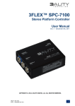
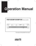
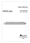
PP-6214Pre Amplifier
* Rack mount products in the Western Hemisphere(North America, South America,
and the Caribbean) do not have handles installed due to customer preference.
Contents
Welcome
Warning.........................................................................................................................................1
Unpacking ......................................................................................................................................2
Installation
Environment....................................................................................................................................2
Important Safety Instructions.............................................................................................................2
Features............................................................................................................................................3
Accessories.....................................................................................................................................3
Operation ........................................................................................................................................3
Front Panel ......................................................................................................................................4
Rear Panel .......................................................................................................................................6
Applications ....................................................................................................................................8
Block Diagram ................................................................................................................................9
Specifications ................................................................................................................................10
Service
Procedures....................................................................................................................................11
Schematic .....................................................................................................................................11
Parts List .......................................................................................................................................11
Variations and Options ...............................................................................................................11
Warranty .......................................................................................................................................11
PRE AMPLIFIER
Welcome
A personal welcome to you from the management and employees of Inter-M
All of the co-workers here at Inter-M are dedicated to providing excellent products with inherently good value,
and we are delighted you have purchased one of our products.
We sincerely trust this product will provide years of satisfactory service, but if anything is not to your complete
satisfaction, we will endeavor to make things right.
Welcome to Inter-M, and thank you for becoming part of our worldwide extended family!
CAUTION
RISK OF ELECTRIC SHOCK
DO NOT OPEN
CAUTION: TO REDUCE THE RISK OF ELECTRIC SHOCK.
DO NOT REMOVE COVER (OR BACK).
NO USER-SERVICEABLE PARTS INSIDE.
REFER SERVICING TO QUALIFIED SERVICE PERSONNEL.
WARNING
To prevent fire or shock hazard, do not
expose the unit to rain or moisture.
This symbol is intended to alert the user to the
presence of uninsulated “dangerous voltage” within
the product’s enclosure that may be of sufficient
magnitude to constitute a risk of electric shock to
persons.
This symbol is intended to alert the user to the
presence of important operation and maintenance
(servicing) instructions in the literature accompanying
the appliance.
Caution: To prevent electric shock do not use this (polarized) plug with
an extension cord, receptacle or other outlet unless the blades
can be fully inserted to prevent blade exposure.
Attentions: Pour prévenir les chocs électriques ne pas utiliser cette
fiche polarisée avec un prolongateur, une prise de courant
on une autre sortie de courant, sauf si les lames peuvent
étre insérées à fond sans en laisser aucune partie à
découvert.
*Do not install this equipment in a confined space such as a book case or similar unit.
*The apparatus shall not be exposed to dripping or splashing and no objects filled with liquids, such vases, shall be placed on the apparatus.
*Worded: “WARNING FOR YOUR PROTECTION PLEASE READ THE FOLLOWING-WATER AND MOISTURE: Unit should not be used
near water(e.g. near a bathtub, washbowl, kitchen sink, laundry tub, in a wet basement, or near a swimming pool, etc). Care should be taken
so than objects do not fall and liquids are not spilled into the enclosure through openings.”
PP-6214
1
PRE AMPLIFIER
Unpacking
Although your PP-6214 is neither complicated nor difficult to operate, we recommend you take a few minutes to
read this brief manual and familiarize yourself with the important information regarding product features, setup
and operation.
As with most electronic devices, we strongly recommend you retain the original packaging. In the unlikely event
the product must be returned for servicing, the original packaging (or reasonable equivalent) is required.
Installation
Environment
Never place this product in an environment which could alter its performance or reduce its service life. Such
environments usually include high levels of heat, dust, moisture, and vibration.
Important Safety Instructions
1.
2.
3.
4.
5.
6.
7.
8.
Read these instructions.
Keep these instructions.
Heed all warnings.
Follow all instructions.
Do not use this apparatus near water.
Clean only with dry cloth.
Do not block any ventilation openings. Install in accordance with the manufacturer’s instructions.
Do not install near any heat sources such as radiators, heat registers, stoves, or other apparatus (including
amplifiers) that produce heat.
9. Do not defeat the safety purpose of the polarized or grounding-type plug. A polarized plug has two blades
with one wider than the other. A grounding type plug has two blades and a third grounding prong. The wide
blade or the third prong are provided for your safety. If the provided plug does not fit into your outlet, consult
an electrician for replacement of the obsolete outlet.
10. Protect the power cord from being walked on or pinched particularly at plugs, convenience receptacles, and
the point where they exit from the apparatus.
11. Only use attachments/accessories specified by the manufacturer.
12. Use only with the cart, stand, tripod, bracket, or table specified by the manufacturer, or sold with the apparatus.
When a cart is used, use caution when moving the cart/apparatus combination to avoid injury from tip-over.
13. Unplug this apparatus during lightning storms or when unused for long periods of time.
14. Refer all servicing to qualified service personnel. Servicing is required when the
apparatus has been damaged in any way, such as power-supply cord or plug is
damaged, liquid has been spilled or objects have fallen into the apparatus, the
apparatus has been exposed to rain or moisture, does not operate normally, or has
S3125A
been dropped.
S3125A
2
PP-6214
PRE AMPLIFIER
Features
- VERSATILE AND COMPACT
Flexible mix architecture in a space-saving two RU package.
- TWELVE INPUTS AND TWO OUTPUTS
Eight mono inputs and two stereo inputs, plus a stereo output.
- INPUT AND OUTPUT METERING
Peak meters on input channels, plus multi-segment LED metering to monitor your output signal.
- THREE-BAND EQ
Three-Band EQ control on output section
- ON-BOARD PHANTOM POWER
Built-in +18VDC phantom power for condenser microphones
- AC OR DC OPERATION
Runs on 100-120VAC, 220-240VAC, or 24VDC for true portability.
Accessories
One detachable AC power cord is provided for use with this product.
Operation
Make certain that speakers and input sources are properly connected before switching on.
Keep volume levels turned down before switching on.
NOTE: The system’s operation is delayed by approximately three seconds after pressing the power switch. This is
due to the built-in protection circuitry, designed to protect speakers and other system components.
PP-6214
3
PRE AMPLIFIER
Front Panel
1
2
9214
PP
PEAK
PEAK
3
4
PRE AMPLIFIER
PEAK
1
PEAK
PEA
PEAK
PEAK
PEAK
4dB
4dB
10dB
10dB
20dB
20dB
12
16
60
TRIM
16
14 TRIM
60
30
16
1
14 TRIM
1
60
6
30
3
16
14 TRIM
60
30
16
14 TRIM
60
30
16
14 TRIM
60
30
16
14 TRIM
60
30
16
14 TRIM
8KHz
EQ
5
6
7
2
12
12
12
12
12
12
8KHz
10dB
12
60
30
1
1
1
1
1
1
1
1
1
1
2
2
2
2
2
2
2
2
2
2
12
12
800Hz
80Hz
800Hz
80Hz
12
ON
12
OFF
0
10
CHANNEL
8
0
10
CHANNEL
0
10
CHANNEL
0
10
CHANNEL
0
10
CHANNEL
9
0
10
CHANNEL
0
10
CHANNEL
0
10
CHANNEL
0
CHANNEL
10
0
10 CHANNEL
10
0
12
10
1
0
PRIORITY
10
2
1
MAIN
2
POWER
10
11
1. TRIM CONTROLS 1-8
These knobs provide continuous control of the gain level for the associated input channel.
2. PEAK INDICATORS 1-8
These LED indicators light when the input signal to the associated channel is 3dB below clipping. If the
indicator is lit steadily, reduce the channel’s Trim level (1) to avoid distortion.
3. GAIN SELECT SWITCHES 9/10 – 11/12
These switches select the input gain level for Stereo Channels 9/10 and 11/12. You may select between
+4dB, -10dB or –20dB input level, depending on your input source. If the signal is too weak (very low level),
select a higher setting; if the signal is too hot (overloaded and distorted), select a lower setting.
4. EQ CONTROLS
These knobs provide continuous control of equalization for the stereo (master) output. Three bands of
equalization are provided:
Low: 80Hz, ±12dB, Shelving
Mid: 800Hz ±12dB, Shelving
High: 8kHz ±12dB, Shelving
5. MAIN OUTPUT LEVEL CONTROLS
These sliders provide control of the stereo (master) output level. The output level may be monitored
by the Output Level Meters (6).
6. OUTPUT LEVEL METERS
These five-segment LED meters monitor the level of the stereo (master) output signal.
4
PP-6214
PRE AMPLIFIER
7. PHANTOM POWER SWITCH AND INDICATOR
Pressing this switch activates the +18VDC phantom power supply to the Mic Inputs 1-8, for use with
condenser mics requiring external power. When Phantom Power is active, the LED indicator lights. Push this
switch again to turn off Phantom Power.
8. CHANNEL SELECTOR SWITCHES 1-8
These buttons assign the channel’s input signal to one or both of the stereo outputs.
9. CHANNEL OUTPUT LEVELS 1-8
These knobs provide continuous control of the associated channel’s output level.
10. PRIORITY LEVEL CONTROL
This knob provides continuous control of the volume of the input signal of the chime, siren, or other audio
source connected to the Priority Input jacks on the rear panel. When signal is present at the Priority Input
jacks, all other signals except Channel 1 are muted.
11. POWER SWITCH
Pressing this switch turns the unit on, as indicated by the Power LED in the switch. Pressing it again
turns the unit off.
PP-6214
5
PRE AMPLIFIER
Rear Panel
1
2
3
INSERT
4
REC OUTPUT
INSERT
5
PRIORITY INPUT
6
MUTE
ON
OFF
FUSE
T400mAL/250V
OUTPUT
S N
LINE
LINE
LINE
LINE
LINE
LINE
LINE
MIC
MIC
MIC
MIC
MIC
MIC
MIC
11
OUTPUT
CH 12
CH 11
CH 10
CH 9
MIC
~ AC INPUT
230V 50Hz
CH 2
CH 1
DC INPUT
24V
7
8
CH 8
9
CH 7
CH 6
CH 5
CH 4
CH 3
CH 2
CH 1
10
1. AC FUSE HOLDER
This holder contains the AC overload protection fuse. If the fuse has blown out, replace it with a fuse of the
same type and rating. If the fuse continues to blow, refer servicing to a qualified service technician.
2. INSERTS
These unbalanced 1/4” TRS jacks are provided for input of an audio source before the master fader. The
input signal is unaffected by the Channel Input levels.
3. LINE INPUTS 9-12
Line-level inputs on unbalanced RCA and 1/4” phone connectors. These are provided as two sets of stereo
inputs (9/10 and 11/12).
4. REC OUTPUT
These two unbalanced 1/4” line-level inputs are provided for connecting to an external recording device.
5. PRIORITY INPUT
These two unbalanced 1/4” line-level inputs are provided for priority connection of chime/siren equipment.
When input signal is present on these inputs, all other audio inputs except Channel 1 are automatically
muted.
6. MUTE SWITCH
When this switch is pressed, priority muting is activated, and all signals except Channel 1 and Priority Input
are muted.
7. AC POWER INPUT
Connect the supplied standard AC input cable here.
6
PP-6214
PRE AMPLIFIER
8. MAIN OUTPUTS
These are balanced XLR output jacks for connecting to the input of a power amp.
9. DC INPUT TERMINALS
These terminals are provided for the connection of backup battery. Connect a 24VDC battery source to these
terminals. Make certain the red terminal is connected to the battery’s positive (+) side, and the black terminal
to the battery’s negative (–) side.
10. MIC INPUTS 1-8
Mic-level inputs on balanced three-pin XLR connectors.
11. LINE INPUTS 2-8
Line-level inputs on balanced 1/4” phone connectors.
PP-6214
7
PRE AMPLIFIER
Applications
DIGI-LINK
~AC INPUT
120V 60Hz, 11W
PT-9107SD
OUTPUT
FIXED
FUSE
T315mAL / 250V
DC INPUT
24V
S N
VARIABLE
MONO(BAL) RESET
MONO(BAL)
ANT
FM
R
L
STEREO
AM
LOOP
ANT.
UNBAL / 75Ω
www.inter-m.com
PC-9335
WEST
MINSTE
CAUTION; TO REDUCE THE RISK OF ELE-
PE-9103A
CTRIC SHOCK, DO NOT REMOVE COVER.
NO USER SERVICEABLE PARTS INSIDE.
REFER SERVICING TO QUALIFIED SERVICE
PERSONNEL.
AVIS; RISQUE DE CHOC ELECTRIQUE NE
PAS OUVRIR.
S N
2 TONE
MODEL NO. PE-9103A
CHIME/SIREN
MADE IN KOREA
DC INPUT
24V
OUTPUT
REMOTE CHIME
CD-3500
INSERT
REC OUTPUT
INSERT
PRIORITY INPUT
MUTE
ON
OFF
OUTPUT
LINE
LINE
LINE
LINE
LINE
LINE
MIC
MIC
MIC
MIC
MIC
MIC
MIC
OUTPUT
PP-6214
CH 12
CH 2
S N
LINE
CH 11
CH 10
CH 9
MIC
CH 1
DC INPUT
24V
CH 8
CH 7
CH 6
CH 5
CH 4
CH 3
CH 2
CH 1
MIC
PA-9312
PA-9324
(RACK ONLY)
SWITCHED
DC OUT 24V
5A MAX
SWED 1
(2000W)
UNSWITCHED
REMOTE
DC OUTPUT 24V,1AMAX C-SW-H
(AMP ONLY)
SWITCHED DC OUT 24V
EMERGENCY
( )
GND
( )
PD-9359E
( )
SWED 2
(2000W)
BATTERY
INPUT 24V
AC FUSE
T2AL/250V
DC FUSE
T5A/250V
SWED 3
(2000W)
UNSWED
(700W)
( )
( )
AC INPUT
230V 50Hz, 217VA
S N
www.inter-m.com
~ AC INPUT
230V/50Hz,217VA
AC INPUT
PB-9207A
BATTERY IN
~ AC INPUT : 220V 50Hz, 139VA
FUSE : 1A / 250V
( )
( )
S
N
BATTERY
(DC 24V)
8
PP-6214
PRE AMPLIFIER
Block Diagram
PP-6214
9
PRE AMPLIFIER
Specifications ..............................................................
- ELECTRICAL
Frequency Response (+1/-3dB)...................................................................................................
T.H.D ..........................................................................................................................
Input Sensitivity/Impedance
Mic Input 1-8 ..........................................................................................................-60dB/60
Line Input 2-8 ..........................................................................................................-30dB/1
Line Inputs 9-12 ..............................................................................+4dB, -10dB, -20dB/10k
Output/Impedance
Ch 1-2 (Master)........................................................................................................+4dB/600
Rec Out ..............................................................................................................-10dB/10k
Insert......................................................................................................................0dB
Residual Noise
All Faders Min.................................................................................................................
All Faders Min, Master Fader Max...............................................................................................
Crosstalk
Input to Output ................................................................................................................
Adjacent .......................................................................................................................
0dB=0.775Vrms
20Hz-20kHz
...........Less than 0.5%
0Ω Balanced
0kΩ Balanced
Ω Unbalanced
Ω Balanced
Ω Unbalanced
/10k Ω Unbalanced
..................90dB
.......70dB
..................70dB
....................70dB
- GENERAL
Power Source.............................................100–120VAC or 220–240VAC; 50/60Hz, 24VDC Auto-Switching
..............................................................
(Supplied AC mains transformer depends on country requirements)
Power Consumption ..............................................................................................................
...............9.8W
Weight .........................................................................................................................
.........12.8kg/34.3lb
Dimensions ................................................................482(W) x 88(H) x 280(D)mm/19(W) x 3.5(H) x 11(D)in
* Specifications and design subject to change without notice.
10
PP-6214
PRE AMPLIFIER
Service
Procedures
Ensure the problem is not related to operator error, or system devices that are external to this unit. Information
provided in the troubleshooting portion of this manual may help with this process. Once it is certain that the
problem is related to the product contact your warranty provider as described in the warranty section of this
manual.
Schematic
A Schematic is available by contacting your warranty provider.
Parts List
A Parts List is available by contacting your warranty provider.
Variations and Options
Variations
Products supplied through legitimate sources are compatible with local AC power requirements.
Options
No optional items are available for this product.
Wa rranty
Warranty terms and conditions vary by country and may not be the same for all products. Terms and conditions
of warranty for a given product may be determined first by locating the appropriate country which the product
was purchased in, then by locating the product type.
To obtain specific warranty information and available service locations contact Inter-M directly(in Korea or the
USA) or the authorized Inter-M Distributor for your specific country or region.
PP-6214
11
PP-9214_E(215.9*279.4)
05.12.13 6:51 PM
페이지1