1
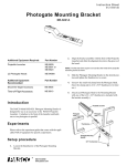
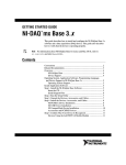
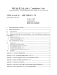
012-05760B
Free Fall Adapter
012-05760B
4/99
Instruction Manual and
Experiment Guide for
the PASCO scientific
Model ME-9207B
FREE FALL ADAPTER
© 1995 PASCO scientific
$7.50
i
Free Fall Adapter
012-05760B
ii
012-05760B
Free Fall Adapter
Table of Contents
Section .......................................................................................................... Page
Copyright, Warranty, and Equipment Return ..................................................... iv
Introduction ....................................................................................................... 1
Equipment ......................................................................................................... 1
Operation ........................................................................................................ 2-3
Troubleshooting ................................................................................................ 3
Experiment: Measuring g ................................................................................. 4-5
Suggested Additional Experiments ..................................................................... 5
Appendix A: Options for using the ME-9207A ................................................. 6
Appendix B: Connecting to Computer Interfaces ............................................... 7
Appendix C: Technical Data ............................................................................. 8
Technical Support ................................................................................... Back Cover
i
Free Fall Adapter
012-05760B
Copyright, Warranty, and Equipment Return
Please—Feel free to duplicate this manual
subject to the copyright restrictions below.
Copyright Notice
Equipment Return
The PASCO scientific 012-05760 Model ME-9207B
Free Fall Adapter manual is copyrighted and all rights
reserved. However, permission is granted to non-profit
educational institutions for reproduction of any part of
the manual providing the reproductions are used only for
their laboratories and are not sold for profit. Reproduction under any other circumstances, without the written
consent of PASCO scientific, is prohibited.
Should the product have to be returned to PASCO
scientific for any reason, notify PASCO scientific by letter,
phone, or fax BEFORE returning the product. Upon
notification, the return authorization and shipping instructions will be promptly issued.
NOTE: NO EQUIPMENT WILL BE
ACCEPTED FOR RETURN WITHOUT AN
AUTHORIZATION FROM PASCO.
Limited Warranty
When returning equipmenmt for repair, the units must
be packed properly. Carriers will not accept responsibility for damage caused by improper packing. To be
certain the unit will not be damaged in shipment,
observe the following rules:
PASCO scientific warrants the product to be free from
defects in materials and workmanship for a period of
one year from the date of shipment to the customer.
PASCO will repair or replace at its option any part of
the product which is deemed to be defective in material
or workmanship. The warranty does not cover damage
to the product caused by abuse or improper use. Determination of whether a product failure is the result of a
manufacturing defect or improper use by the customer
shall be made solely by PASCO scientific. Responsibility for the return of equipment for warranty repair
belongs to the customer. Equipment must be properly
packed to prevent damage and shipped postage or
freight prepaid. (Damage caused by improper packing of
the equipment for return shipment will not be covered
by the warranty.) Shipping costs for returning the
equipment after repair will be paid by PASCO scientific.
➀ The packing carton must be strong enough for the
item shipped.
➁ Make certain there are at least two inches of
packing material between any point on the apparatus and the inside walls of the carton.
➂ Make certain that the packing material cannot shift
in the box or become compressed, allowing the
instrument come in contact with the packing
carton.
ii
Address:
PASCO scientific
10101 Foothills Blvd.
Roseville, CA 95747-7100
Phone:
FAX:
email:
web:
(916) 786-3800
(916) 786-3292
[email protected]
www.pasco.com
012-05760B
Free Fall Adapter
Introduction
In the basic free fall experiment, a steel ball is
clamped into the spring loaded release mechanism.
The ball is in series with the triggering circuit for the
photogate timer. When the thumbscrew is turned, the
mechanism pops open, releasing the ball and starting
the timer. When the ball strikes the receptor pad, the
top plate of the pad is forced against the metal base.
This automatically stops the timer. The timer display
shows the time it took for the ball to drop from the release mechanism to the pad.
The PASCO Model ME-9207B Free Fall Adapter is an
automatic release mechanism that plugs into PASCO
Photogate Timers, Smart Timer, ScienceWorkshop®
computer interfaces, and other electronic timing
devices, allowing you to measure the acceleration due
to gravity (g) with 1 percent accuracy. It is also easily
adapted for a variety of other mechanics experiments,
providing a highly accurate method for starting and
stopping the electronic timers. Some examples of
these other uses are provided at the end of this
manual.
Equipment
Equipment Included:
ball release
mechanism
• Free Fall Adapter: (ball release mechanism, receptor pad, controller box, cable, and phone jack connector)
• 2 steel balls (1.27 cm diameter)
steel ball
• 2 steel balls (1.91 cm diameter)
controller box
Additional Equipment Required:
• clamp (such as the PASCO SE-9446 Buret Clamp
• rod stand
phone plug
(Connect to
Photogate Timer)
• electronic timing device (such as the PASCO ME9403 Photogate Timer, PASCO ME-8930 Smart
Timer, PASCO ScienceWorkshop® computer interface (500 or 700 series and CI-6500)
receptor pad
• metric stick
Figure 1. Free Fall Adapter: Included Equipment
1
Free Fall Adapter
012-05760B
Operation
Connecting the Free Fall Adapter to the
Electronic Timing Device
For best results, the drop height (d) should be the
full two meters allowed by the cable. Shorter
heights will work fine, but accuracy is reduced
proportionally.
The Free Fall Adapter connects the any electronic
timing device by inserting the phone plug into a
phone jack on the device. See Appendix A for a
diagram of many of the connection options. See
Appendix B for illustrated connection instructions for
several of these timing devices.
2. Position the ball receptor plate directly under the
Options for Electronic Timing
3. Insert one of the steel balls into the release mecha-
ball. (You might want to place the receptor plate
in a shallow box so the ball doesn’t roll away after
it falls.)
nism, pressing in the dowel pin so the ball is
clamped between the contact screw and the hole in
the release plate. Lightly tighten the thumbscrew
to lock the ball in place.
Options for electronic timing for the Free Fall
Adapter include the PASCO Photogate Timers
(Model 9206A, or 9215A), Smart Timer
(ME-8930), and ScienceWorkshop® computer interface (Series 500, 700, and CI-6500)V. If you
wish to use this adapter with other timers, please
see the Technical Information section (Appendix
C) for power supply, output signal, and connector
specifications.
4. Plug the phone jack into a port on your electronic
timing device.
Data Collection
The process for data collection varies with the electronic timing device. The process for a few of these
devices is listed below:
Equipment Setup
1. Clamp the ball release mechanism to a lab stand, or
any other device that will hold it vertical and at the
desired height over the floor or table (Figure 2).
PASCO Photogate Timer (ME-9206A or ME9215A)
1. Turn the timer ON and set it in the GATE mode.
ball release
mechanism
2. Tap the receptor pad to reset the Free Fall Timer
electronics.
dowel pin
(press
here)
3. Press the RESET button to reset the timer.
4. Loosen the thumbscrew to release the ball. It
thumbscrew
on back side
should hit in the center of the receptor pad. If not,
reset the timer, reposition the pad, and try it again.
contact screw
Photogate Timer
(not included)
5. Read the time on the digital display of the timer.
This is the time it took for the ball to fall a distance
d, as shown in Figure 2.
d
PASCO Smart Timer (ME-8930
1. Press the Select Measurement button repeatedly
until Time is displayed.
2. Press the Select Mode button repeatedly until the
Stopwatch mode is displayed.
receptor pad
Figure 2. Equipment Setup
2
012-05760B
Free Fall Adapter
Data Collection, continued
Note: In ScienceWorkshop, you can specify the
distance d for automatic calculation of acceleration
due to gravity (g). In DataStudio, g is calculated
automatically assuming d = 1 meter.
3. Press the Start/Stop button once.
Result: An asterisk will appear on the display indicting that the Smart Timer is ready to collect
Time of Fall data.
2. Open an appropriate display for the data (such as
the Digits display in ScienceWorkshop® and
DataStudio™.
4. Loosen the thumbscrew to release the ball. It
should hit in the center of the receptor pad. If not,
reset the timer, reposition the pad, and try it again.
Result: The Smart Timer will display the time of
fall in seconds.
Note: In ScienceWorkshop and DataStudio, the
acceleration due to gravity is automatically
displayed if the appropriate display has been
opened.
5. Read the time on the digital display of the timer.
This is the time it took for the ball to fall a distance
d, as shown in Figure 2.
3. Start recording data.
6. To prepare to take another measurement,
reposition the ball in the ball release mechanism,
and press the Start/Stop button to reset the Smart
Timer.
4. Loosen the thumbscrew to release the ball. It
should hit in the center of the receptor pad. If not,
reposition the pad, and try it again.
Result: The time of fall (s) will be displayed.
Acceleration due to gravity (g) (m/s/s) will also be
displayed if the appropriate display and conditions
have been set up as described above.
PASCO ScienceWorkshop Computer Interfaces
(Series 500 and 700)
1. Set up the Free Fall Adapter to be recorded in your
data acquisition software.
Note: Refer to the User Manual or on-line help for
details.
Troubleshooting
In Case of Difficulty
Problem with PASCO Photogate Timer:
If the timer does not begin timing when the ball is released or fails to stop timing when the ball hits the receptor pad, check the following:
➤ If your timer readout has missing or extra segments
or the timer will not count or keeps counting even
after checking the above conditions, then the batteries probably need replacement.
1. Check that the ball, or whatever object you are tim-
Problem with PASCO Computer Interfaces:
ing, makes electrical contact between the contact
screw and the flat-spring of the ball release. If necessary, clean the contact, flat-spring, and ball. (An
object made of plastic, wood, or another nonconductive material won't trigger the timer when released.)
➤ Recent upgrades in the Precision Timer III and
Smart Pulley Timer software allow the user to
choose either our original ME-9207 or our newer
ME-9207A Free Fall Adapter. The instruction for
using the two models differs due to changes in the
circuitry. For further information on using the ME9207 Free Fall Adapter with your software, or to
obtain a current edition of the software, contact the
technical support department at PASCO (1-800772-8700).
2. Check that the target pad does not touch the metal
base of the receptor pad but is close enough (1 to 2
mm) so that it will contact the metal base when the
falling object strikes it.
3
Free Fall Adapter
012-05760B
Experiment: Measuring g
Introduction
The equation of motion for a body starting from rest and undergoing constant acceleration can
2
be expressed as: x = a
2
where x is the distance the object has traveled from its starting point, a is the acceleration, and
t is the time elapsed since the motion began.
In order to measure the acceleration caused by gravity, several questions must be answered:
•Is the acceleration constant? If it is, then the distance an object falls will be proportional to
the square of the elapsed time, as in the above equation.
•If the acceleration is constant, what is the value of the acceleration? Is it the same for all
objects or does it vary with mass or size of the object, or with some other quality of the object? If it is not constant, how does it vary with time?
In this experiment you will answer these questions by carefully timing the fall of a steel ball
from various heights.
Procedure
1. Set up the Free Fall Timer as described in the SETUP and OPERATION section of this manual.
Use the 13 mm diameter steel ball.
2. Set d, the height from which the ball drops, to approximately 2.0 meters. Measure the distance
as accurately as possible and record the distance in Table 1. Follow the instructions for the
Timer or Computer Interface as given in the “Operations” section. Record the measured time
as t1 in Table 1. Repeat the measurement at least four more times and record these values as t2t5. Calculate the average of your five measured times and record this value as tavg.
3. Set d to 1.75, 1.50, 1.25, 1.00, 0.75 and 0.50 m, repeating step 2 for each value of d. (The
actual value of d need not correspond exactly to the listed values, but be sure you measure it
carefully.)
4. Repeat steps 2 and 3 using the 16 mm steel ball.
Analysis
For each ball, plot a graph of d versus tavg2 with d as the dependent value (y-axis). Within the
limits of your experimental accuracy, do your data points define a straight line for each ball?
Was the acceleration constant for each ball?
Table 1 Data and Calculations
d (m)
t1
t2
t3
t4
4
t5
tavg
tavg2
012-05760B
Free Fall Adapter
If your graphs were linear, measure the slope of each graph. Using your measured slopes
and the equation shown in the introduction to this experiment, determine the acceleration
caused by gravity. Be sure to include the units. Was the acceleration the same for each
ball?
Conclusion
Describe your laboratory experiment and discuss your results. Consider the following
questions: (1) Is the acceleration caused by gravity constant? (2) Is the acceleration
caused by gravity the same for all objects? Discuss the conditions under which you believe your results to be true. Include a discussion of the errors in your measurements and
how they affect your conclusions. How linear was your graph? How might you alter
your technique, or the experiment, in order to reduce experimental errors?
Suggested Additional Experiments
The Free Fall Apparatus can bring high resolution
timing to a variety of mechanics experiments. Any
conductive object can be timed as long as it can be
clamped in the release mechanism and is heavy enough
to depress the receptor plate when it strikes. The
illustrations below show some examples of
experimental setups.
We'd like to thank Giles Shepherd of Everett Community College for suggesting the experiments
shown below.
Atwood’s Machine
Inclined Plane 2
Compare the velocities of a solid disk and a
ring as they roll down an inclined plane.
Investigate F=ma
using a highly
accurate Atwood’s
Machine.
Ring Stand
A short screw through
the hole in the release
plate will help hold the
cylinder in the release
mechanism.
Inclined Plane 1
Determine the acceleration of a cart pulled by
a constant force on a flat or inclined surface.
metal disk
or ring
inclined plane
receptor pad
5
Free Fall Adapter
012-05760B
Appendix A: Options for using the
ME-9207B Free Fall Adapter
CS828N-2+, DF9+*
!"#$%&4/,8*
!"#$%65/
/3#45&6
7891:2+*,3;2+*<-=+
>/11.+33?,33+?,33@AB
A9-*2,DF9+*
!"#L$P&
/3#45'5,@-9+,C8*2
3;2+*<-=+,(8K
>/11.+33?,33+?,33@AB
!"#$PQP/, /11.+
/0-12+*, 7-R.+
>/11.+33+?,33=?,33@AB
/11.+,7891:2+*
CD,333
ACD
3IA,DF9+*
!"#$%&'(
)*++,)-..
/0-12+*
!"#$%"$&'()*+',
3;2+*<-=+G,>5&&,-;0
'&&,A+*F+GB
73#45&&
7891:2+*,3;2+*<-=+
>O8;#!7/B
3(!,#,7891-2FR.+
7891:2+*
CD
ACD
3IA,DF9+*
!-=,DF9+*
!-=F;28GS
7891:2+*
!"#$%"$
&'()*+',
CD,333,,E,,C*+=FGF8;,DF9+*,333,,>/11.+,33B
ACD,,,E,,A9-*2,C:..+H,DF9+*
CD,,,,,E,,,C*+=FGF8;,DF9+*,>!A#IJAB
3IA,,,,E,,3;2*80:=28*H,IH;-9F=G,AHG2+9
!"#$%&'()&(*&+,-&.(/01234
5*4036(70&7(38&(9(5:(;:0<&&#=>?@AB
6
73#45LL, @-9+, C8*2
3;2+*<-=+,(8K
>*+M:F*+G,65,1F;
N-9+,18*2B
!"#$Q&%,3(!
/0-12+*,7-R.+
>*+M:F*+G,65,1F;
N-9+,18*2B
73#4'&&
!-=,DF9+*
3;2+*<-=+
73#455&
!-=,45
3;2+*<-=+
!"#$%"$&'()*+',
3;2+*<-=+G,>5&&,-;0
'&&,A+*F+GB
012-05760B
Free Fall Adapter
Appendix B: Connecting to Computer Interfaces
Using the AI-6575 Apple Gameport Interface:
Using the CI-6588 IBM PC Gameport
Interface:
Connect the ME-9207B Free Fall Adapter into
connector 1 on the Gameport interface box as shown
in Figure 3.
Connect the ME-9207B Free Fall Adapter into
connector 1 on the IBM Gameport interface box as
shown in Figure 5.
Gameport Interface
Inside Apple
II+ or IIe
15-Pin
Connector
Gameport Interface
6
Gameport
Back of IBM
Computer
Phone Plug
from Free Fall
Adapter
%
P
Q
Stereo Phone
Plug from
Free Fall
Adapter
Gameport
Figure 3
Using the ME-9343A Adapter Cable:
Figure 5
Connect the ME-9207B Free Fall Adapter into connector 1 on the ME-9343A (the connector with the
black shrink-wrap marking) as shown in Figure 4.
Using the ME-9402 IBM Adapter Cable:
Connect the Free Fall Adapter into the jack with the black
tape.
Stereo Phone
Plug from Free
Fall Adapter
15-Pin Game
Port Interface
Card
15-Pin
Connector
Gameport
9-Pin Connector
Adapter Cable
Adapter Cable
Back of IBM Computer
Figure 4
Figure 6
Using the AI-6501 or CI-6500 Series 6500
Computer Interface:
Using the ScienceWorkshop 500 Computer
Interface
Connect the Free Fall adapter to digital input 1 on the
Series 6500 interface box.
Plug from
Free Fall
Adapter
Connect the Free Fall Adapter to digital input 1 on the
interface.
Ribbon Cable
to Computer
Digital Input 1
73#456&,!-./012-/3456074
/O/TJ@,,7U/OO"TA
C%D&E#=&F+GH&!"#$%&#=D+=#&?@BB&#=I#%D#
6
C/A7J
I3@3D/T,,7U/OO"TA
%
P
"&&&&&&&!
,&&&&&&&"
$&&&&&&#
J"+I&K&L<LB<LBB
+#%M"G=N
J"+I&K&L
+#%M"G=N
J"+I&K&L
D=C&G%&JIN
Q
JO
)$%!$)
45&&
!"#$%&'($
)*)#$+
73#456&,!-./012-/3456074
Digital Input 1
Figure 7
Figure 8
7
Phone Plug
from Free Fall
Adapter
Free Fall Adapter
012-05760B
Appendix C: Technical Data
Timer Specifications for the Free Fall
Adapter
+5 Volt
The PASCO ME-9207B Free Fall Adapter can be used
with any timer that will:
Signal Out
1/4”
Stereo
Phone
Jack
1. Provide 5 VDC at 50 mA.
2. Provide a minimum resolution of 1 ms.
Ground
3. Begin counting on the negative slope of a pulse
and stop counting on the positive slope of the
pulse.
The connections for the stereo phone jack are indicated in Figure 6. The schematic is shown below.
NOTE: All resistors are 1/4 W, 5% unless
otherwise noted.
Figure 9. Stereo Phone Jack Connections
Schematic Model ME-9207B Free Fall Adapter (956-03527A)
8
012-05760B
Free Fall Adapter
Technical Support
Feedback
Contacting Technical Support
If you have any comments about the product or
manual, please let us know. If you have any suggestions on alternate experiments or find a problem in the
manual, please tell us. PASCO appreciates any customer
feedback. Your input helps us evaluate and improve
our product.
Before you call the PASCO Technical Support staff, it
would be helpful to prepare the following information:
➤ If your problem is computer/software related, note:
! Title and revision date of software;
! Type of computer (make, model, speed);
To Reach PASCO
! Type of external cables/peripherals.
For technical support, call us at 1-800-772-8700 (tollfree within the U.S.) or (916) 786-3800.
fax:
➤ If your problem is with the PASCO apparatus,
note:
(916) 786-3292
! Title and model number (usually listed on the
e-mail: [email protected]
web:
label);
www.pasco.com
! Approximate age of apparatus;
! A detailed description of the problem/sequence
of events (in case you can’t call PASCO right
away, you won’t lose valuable data);
! If possible, have the apparatus within reach when
calling to facilitate description of individual parts.
➤ If your problem relates to the instruction manual,
note:
! Part number and revision (listed by month and
year on the front cover);
! Have the manual at hand to discuss your
questions.
9