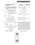
1
US008261100B2
(12) United States Patent
(10) Patent N0.:
(45) Date of Patent:
Paniagua, Jr. et a1.
(54)
(56)
POWER ADAPTER CAPABLE OF
COMMUNICATING DIGITALLY WITH
ELECTRONIC DEVICES USING
PACKET-BASED PROTOCOL
(US); Parag Mody, Oakland, CA (US);
Hossein Yassaie, Bucks (GB)
(73) Assignee: Green Plug, Inc., San Ramon, CA (US)
Notice:
*Sep. 4, 2012
References Cited
U.S. PATENT DOCUMENTS
(75) Inventors: Frank Paniagua, Jr., San Ramon, CA
(*)
US 8,261,100 B2
5,488,572 A
6,029,215 A
1/1996 Belmont
2/2000 Watts et a1.
7,394,676 B2 *
7/2008
7,531,986 B2 *
5/2009 Eager et a1. .
Patel ........................... .. 363/142
7,646,107 B2 *
1/2010
320/116
Smith ........................... .. 307/11
2006/0046653 A1
2006/0223579 A1
3/2006 Kirbas
10/2006 Whitaker et a1.
2010/0264875 A1*
10/2010
Hoffman et a1. ............ .. 320/111
OTHER PUBLICATIONS
Subject to any disclaimer, the term of this
patent is extended or adjusted under 35
American Power Conversion, 90-Watt-Hour Universal Notebook
U.S.C. 154(b) by 1115 days.
Battery (UPB90) User’s Manual, 2007.*
PCT International Search Report, PCT/US2009/30149.
This patent is subject to a terminal dis
claimer.
PCT Written Opinion of the International Searching Authority, PCT/
US2009/30149.
* cited by examiner
(21) Appl. No.: 11/969,163
Primary Examiner * Albert Wang
(22)
Filed:
(74) Attorney, Agent, orFirm * DLA Piper LLP; Andrew B.
SchWaab; Blake W. Jackson
Jan. 3, 2008
(65)
(57)
ABSTRACT
A poWer adapter capable of communicating digitally With a
Prior Publication Data
US 2008/0222431 A1
Sep. 11, 2008
device or a legacy adapter associated With a device is
described. The poWer adapter includes an input port to receive
Related US. Application Data
poWer from a poWer source, a regulator to convert the
received poWer from the poWer source, an output port con
(63) Continuation-in-part of application No. 11/513,687,
?gured to deliver poWer from the regulator to a device, and a
?led on Aug. 30, 2006, noW abandoned.
microprocessor con?gured to communicate digitally With a
communication module associated With the device to deter
(51)
Int. Cl.
(52)
(58)
US. Cl. ....................... .. 713/300; 320/114; 455/573
Field of Classi?cation Search ................ .. 320/114;
G06F 1/26
mine the poWer requirements of the device. The regulator
(2006.01)
converts the poWer from the poWer source in accordance With
the poWer requirements of the device. A related method of
adapting poWer to a device is also described.
455/573; 713/300
See application ?le for complete search history.
90 Claims, 13 Drawing Sheets
102a
Legacy
1021:
Device
Device
'
Legacy
Adapter
Power Adapter
Power Source
104
US. Patent
Sep. 4, 2012
Sheet 1 0f 13
US 8,261,100 B2
102a
Legacy
102b
Device
Device
' ' 0
Legacy
104
Adapter
Power Adapter
Power Source
FIG. 1
106
US. Patent
Sep. 4, 2012
Sheet 4 0113
US 8,261,100 B2
Device 102a1
: ___________ _ _l
:
Display
i'*\/ 406
| _ _ _ _ _ _ _ _ _ _ _ _ _|
317a
‘g
Microprocessor(s) '\/ 402
To Power
Adapter
319
106
Ea
Memory
\, 408
Battery
N 404
Temperature
Sensor
w 410
FIG. 4
104
(
319c
.
<
,
PQAJLE'EZLZZSSOF
K 502
Legacy Connector
K 11
3 c
506 /-\/
K 504
Microprocessor
Memory
K 508
FIG. 5
US. Patent
Sep. 4, 2012
Sheet 5 0113
US 8,261,100 B2
US. Patent
Sep. 4, 2012
Sheet 6 0113
US 8,261,100 B2
700
Receive power from a
702
power source at an input J
port
l
Communicate digitally
704
with the device
l
Determine the power
requirements of the
706
J
communication module
l
Convert the power from
the power source in
accordance with the
708
power requirements of
the device
l
Deliver the converted
power to the device
through an output port
FIG. 7
_/
US. Patent
Sep. 4, 2012
Sheet 7 0113
US 8,261,100 B2
800
Receive an initial
802
predetermined voltage
from the external power
adapter
1
Communicate digitally
804
with the external power
adapter to communicate
at least a voltage
requirement and a
current requirement
1
Receive power supplied
by the external power
806
adapter based on the
power requirements of
the device
l
Provide the received
808
J
power to the electrical
device
FIG. 8
900
902
\
Transmission
Start
904
\
Vendor
ldentifer
906
\
Message
Type
WW
1 byte
4 bytes
1 byte
908
91 0
\
Payload
Y
Variable
size
FIG. 9
91 2
\
Checksum
1
Y
2 bytes
\
Transmission
End
1
Y
1 byte
1
US. Patent
Sep. 4, 2012
Sheet 8 0113
US 8,261,100 B2
1000
Q
1002
///
\\~____\
I. //
\\\\
Receive
message
1004
1006
Error
OK
100
Proprietary
message
Unrecognized
1010
Power statement
FIG. 10
1012
US. Patent
Sep. 4, 2012
Sheet 9 0113
US 8,261,100 B2
1100
Enter communication
Receive
timeout
Transmission
attempts = 8
1 102
Receive
Backoff
message
Verify
Checksum
1110
Exit communication
FIG. 11
US. Patent
Sep. 4, 2012
Sheet 13 0113
US 8,261,100 B2
1302a
DC In
1304a
(
/
josa
Fixed Regulator
‘sense
1308a 1302b
1304b
(
/
1306b
Fixed Regulator
‘sense
1308b 1302c
1304c
(
Adjustable
1306c
/
/
Regulamr
lsense
—>
13080
From
Microprocessor
if
1312
PWM In
FIG. 13
1310
VREF
1409
1402
l 1
)
1418
\J
14(14a
, [189%
AC In
> Fixed Regulator
1404
Aélvgc
1416a
1416b
1414b
/
I
/
> Fixed Regulator
I
1408
/
1414c
/
(
Adjustable '/
b
1406
Y
1416c
Regulator
1410
\ Digital
Comm‘
:
To Device
—>
US 8,261,100 B2
1
2
POWER ADAPTER CAPABLE OF
COMMUNICATING DIGITALLY WITH
ELECTRONIC DEVICES USING
PACKET-BASED PROTOCOL
the poWer source in accordance With the poWer requirements
of the device, and delivering the converted poWer to a device
through an output port.
According to some embodiments, a poWer adapter includes
an input port to receive poWer from a poWer source, one or
more regulators to convert poWer from the poWer source, a
RELATED APPLICATIONS
plurality of output ports con?gured to deliver poWer from the
This application claims priority to and is a continuation
in-part of US. patent application Ser. No. 11/513,687, noW
one or more regulators to a plurality of devices, and a micro
processor con?gured to communicate digitally With a respec
tive communication module associated With a respective
device to determine poWer requirements of the respective
abandoned titled “Power Supply Capable of Receiving Digi
tal Communications from Electronic Devices,” ?led Aug. 30,
2006, Which is incorporated by referenced herein in its
device. One of the one or more regulators converts the poWer
entirety.
from the poWer source in accordance With the poWer require
ments of the respective device.
According to some embodiments, a method of adapting
poWer to a plurality of devices includes receiving poWer from
a poWer source at an input port, communicating digitally With
TECHNICAL FIELD
The disclosed embodiments relate generally to poWer
adapters, and more particularly, to a poWer adapter that is
capable of communicating digitally With devices to be poW
ered by the poWer adapter.
a communication module associated With a respective device
20
poWer source in accordance With the poWer requirements of
BACKGROUND
the respective device, and delivering the converted poWer to
the respective device through one of a plurality of output
Consumer electronic devices are ubiquitous in the World
We live in today. From laptop computers and personal digital
assistants to multimedia players and mobile phones, people
25
30
other. If a user loses a poWer supply for a device, the poWer
supply of another device generally cannot be used as a sub
stitute. This causes many problems. Travel is made more
35
adapter through a port of the electrical device, the poWer
requirements including at least a voltage requirement and a
current requirement.
According to some embodiments, a method of receiving
device includes receiving an initial prede?ned voltage to
facilitate communication betWeen the external poWer adapter
40
be discarded as Well because users often do not have other
devices that are compatible With these poWer supplies.
Accordingly, What is needed is a poWer adapter that can
communicate digitally With and be used to poWer a Wide
variety of devices.
sor, housed in the electrical device, con?gured to communi
cate digitally With an external poWer adapter to communicate
poWer requirements of the electrical device to the poWer
poWer from an external poWer adapter external to an electrical
inconvenient by the prospect of having to bring multiple
poWer supplies for various portable devices. A device may be
damaged and/or its useful life shortened if the Wrong poWer
supply is used. Furthermore, as devices become obsolete and
are discarded by users, the poWer supplies for the devices may
ports.
According to some embodiments, a communication mod
ule for use With an electrical device includes a microproces
today oWn a Wide variety of electronic devices. These elec
tronic devices come With a Wide variety of poWer supplies,
sometimes referred to as “Wall Warts,” “poWer bricks,” or
“poWer adapters.” Unfortunately, these poWer supplies are
often speci?c to the device type, device manufacturer, and/or
device product line, and are therefore incompatible With each
of the plurality of devices to determine the poWer require
ments of the respective device, converting poWer from the
45
and the electrical device, communicating digitally With the
external poWer adapter to communicate poWer requirements
of the electrical device to the external poWer adapter through
a poWer port of the electrical device, and receiving poWer
supplied by the external poWer adapter based on the poWer
requirements of the electrical device. The poWer require
ments include a voltage requirement and a current require
ment.
SUMMARY
BRIEF DESCRIPTION OF THE DRAWINGS
The above de?ciencies and other problems associated With
poWer supplies are reduced or eliminated by the disclosed
poWer adapter and an electronic device that are capable of
digital communications With each other.
50
ments.
FIG. 2 is a schematic illustrating a poWer adapter in accor
dance With some embodiments.
According to some embodiments, a poWer adapter to pro
vide poWer to a device includes an input port to receive poWer
from a poWer source, a regulator to convert the received
55
poWer from the poWer source, an output port con?gured to
deliver poWer from the regulator to the device, and a micro
processor con?gured to communicate digitally With a com
munication module associated With the device to determine
poWer requirements of the device. The regulator converts the
FIG. 1 is a block diagram of a poWer adapter coupled to a
poWer source and devices in accordance With some embodi
FIG. 3 is a schematic diagram of a poWer adapter coupled
to devices, a poWer source, and a legacy adapter in accordance
With some embodiments.
FIG. 4 is a schematic illustrating a device in accordance
With some embodiments.
60
FIG. 5 is a schematic illustrating a legacy adapter in accor
poWer from the poWer source in accordance With the poWer
dance With some embodiments.
requirements of the device.
FIGS. 6A-6C are schematics illustrating a poWer adapter
coupled to a device, a legacy adapter, or a client in accordance
According to some embodiments, a method of adapting
poWer to a device includes receiving poWer from a poWer
source at an input port, communicating digitally With a com
munication module associated With the device to determine
poWer requirements of the device, converting the poWer from
With some embodiments.
65
FIG. 7 is a How diagram illustrating a method of adapting
poWer to one or more devices in accordance With some
embodiments.
US 8,261,100 B2
4
3
poWered by the poWer adapter 106. The external poWer
FIG. 8 is a How diagram illustrating a method of receiving
adapter 106 may be electrically coupled to one or more
power from an external power adapter external to an electrical
device in accordance With some embodiments.
FIG. 9 is a diagram illustrating a packet structure of a
devices 102 via poWer cords, cables, induction, or other
knoWn Ways of transmitting poWer (not shoWn). In some
embodiments, both the poWer adapter 106 and a device 102a
digital communication betWeen the poWer adapter and a
legacy adapter or a device in accordance With some embodi
conform to a common connector or interface standard; the
ments.
poWer cord coupling the poWer adapter 106 to a given device,
such as device 102a includes standardized connectors on one
FIG. 10 is a state diagram illustrating digital communica
or both ends of the cord, and may, in some embodiments, be
non-detachably a?ixed to the poWer adapter 106 on one end.
A device 102a may be designed to use the standardized con
nector and be coupled to the poWer adapter 106 via a cord
tion states of a poWer adapter in accordance With some
embodiments.
FIG. 11 is a state diagram illustrating digital communica
tion states of a client in accordance With some embodiments.
FIGS. 12A-C are circuit schematics illustrating a PFC
Controller in accordance With some embodiments.
plugs and receptacles, the poWer adapter 106 can serve as a
FIG. 13 is a circuit schematic illustrating regulators in
universal poWer adapter to any device that is designed to
having the standardized connectors. By using standardized
include a standardized plug or receptacle, such as a multi
purpose poWer connector.
accordance With some embodiments.
FIG. 14 is a schematic diagram illustrating a poWer adapter
including AC/DC converters and regulators in accordance
With some embodiments.
Like reference numerals refer to corresponding parts
20
throughout the draWings.
DESCRIPTION OF EMBODIMENTS
Reference Will noW be made in detail to embodiments,
25
With the legacy device 1021).
examples of Which are illustrated in the accompanying draW
ings. In the folloWing detailed description, numerous speci?c
In some embodiments, the legacy adapter 104 is a part of a
details are set forth in order to provide a thorough understand
cord that includes the multi-purpose poWer connector on one
end and legacy adapter 104 on the other end, Which includes
ing of the present invention. HoWever, it Will be apparent to
one of ordinary skill in the art that the present invention may
In some other embodiments, the poWer adapter 106 and
legacy device 1021) use different types of poWer connectors.
For example, a device that is not designed to use the multi
purpose poWer connector (e.g., an older device) may have a
legacy poWer connector that is device- or manufacturer-spe
ci?c and not conforming to the standard that is used by the
poWer adapter 106. In such embodiments, the use of a legacy
adapter 104 may be used to interface the poWer adapter 106
30
a device- or manufacturer-speci?c connector. Accordingly,
the poWer adapter 106 may be coupled directly to legacy
be practiced Without these speci?c details. In other instances,
Well-known methods, procedures, components, and circuits
device 102b via a cord that includes the multi-purpose poWer
have not been described in detail so as not to unnecessarily
connector on one end and legacy adapter 1 04 on the other end.
In other Words, the cord is customized to the connector on the
obscure aspects of the embodiments.
FIG. 1 is a block diagram of a poWer adapter coupled to a
35
device because at least one connector on the cord is device- or
poWer source and devices in accordance With some embodi
ments. PoWer source 108 supplies electrical poWer to poWer
manufacturer-speci?c.
adapter 106 in order to supply electrical poWer to devices 102.
The poWer source 108 may provide alternating current (AC)
or direct current (DC) voltage. In some embodiments, the
dongle, may be coupled to legacy device 1021). The dongle
In some other embodiments, an attachment, such as a
40
includes legacy adapter 104 to “convert” the connector on
legacy device 1021) to the standardized connector utilized by
poWer adapter 106 (i.e., the multi-purpose poWer connector).
poWer source 108 is a poWer outlet, such as a Wall outlet. The
poWer outlet voltages outside the United States. In other
When using a dongle that includes legacy adapter 104, a cord
embodiments, the poWer source 108 is an outlet in an airplane
armrest or in an automobile, such as a cigarette lighter socket,
With a multi-purpose poWer connector on both ends may be
Which typically provides 12V DC. In still other embodiments,
45
the poWer source 108 is anAC/DC converter that receives an
AC input and provides a DC output to the poWer adapter 106.
In further embodiments, the poWer source is a motor, genera
tor, battery, etc. that provides electricity. Depending on the
particular embodiment, the poWer adapter 106 may be con
used. One end of the cord couples to the multi-purpose poWer
connector of poWer adapter 106 and the other end couples to
a dongle that includes legacy adapter 104. The other end of
the dongle contains the device- or manufacturer-speci?c con
nector for coupling to legacy device 1021). In other Words, the
dongle With legacy adapter 104 contains both a multi-purpose
50
poWer connector and a device- or manufacturer-speci?c con
nector, thereby alloWing coupling of the poWer adapter 106
?gured for coupling to only a DC poWer source, only an AC
poWer source, or either a DC or AC poWer source. The poWer
and legacy device 1021) via a cord having the multi-purpose
adapter 106 thus functions as anAC/DC converter, a DC/DC
converter, or both, depending on the embodiment. The poWer
adapter 106 may be coupled to the poWer source 108 via a
poWer connector on the device end of the cord.
FIG. 2 illustrates poWer adapter 106 of some embodiments.
55
poWer cord, cable, induction, or other knoWn Ways of trans
adapter 106 has multiple output ports 204 (e.g., 204a, 204b,
mitting poWer.
and 2040). Input port 202 and output ports 204 can be any
The poWer adapter 106 may be coupled to one or more
devices 102. The devices 102 may include any of a variety of
electronic devices, including but not limited to consumer
combination of plugs, receptacles, sockets, magnetic poWer
60
connectors, non-detachable cords, etc. In one embodiment,
the output ports 204 include a receptacle for receiving the
electronic devices, cellular phones, multimedia devices, com
puter devices and peripherals. PoWer adapter 106 may come
in a variety of sizes. For example, poWer adapter 106 may be
implemented in a relatively small size for ease of portability
and travel convenience.
In some embodiments, the poWer adapter 106 is a standa
lone unit, external to and distinct from devices 102 to be
PoWer adapter 106 includes an input port 202 for receiving
poWer from a poWer source, e.g., poWer source 108. PoWer
multi-purpose poWer connector. In another embodiment, one
or more cords are non-detachably ?xed to one or more output
ports 204. PoWer adapter 106 may also include a user inter
65
face for interaction With a user. In some embodiments, the
user interface comprises a status light 206 (e.g., 206a, 206b,
and 2060) associated With each output port 204 that may
US 8,261,100 B2
5
6
indicate whether a device is being powered, whether the
device is being provided reduced power, or other statuses of
FIGS. 12A-C. PFC Controller outputs DC power through
switches 320 to regulators 318a, 318b, and 3180 via PFC
power lines 305a, 305b, and 3050, respectively. In some
embodiments, switches 320 are internal to regulators 318 and
power adapter 106 or devices 102 connected to the power
adapter 106. Status lights 206 can indicate one or more sta
tuses by blinking, changing colors, or the like. The user inter
face of power adapter 106 may also include display 208,
operate as an ENABLE/DISABLE line to disconnect the
which may be an LCD screen, an LED, or an OLED display
for displaying information to a user. In some embodiments,
described in more detail below with reference to FIG. 13. In
output of regulators 318. An example of this embodiment is
some embodiments, regulators 318 are programmable
status information can be displayed on display 208 in addition
to or in place of status lights 206. For example, the back
switching regulators. In some other embodiments, regulators
318 are programmable linear regulators. The switches 320 are
used to disconnect each regulator 318 that is not currently in
ground color of display 208 could change colors or blink
based on the status of the devices 102 or the power adapter
106. In other embodiments, where device 102 includes a
use by a device 102 from PFC power lines 305. In some
display 406 as illustrated in FIG. 4, power adapter 106 may
instruct device 102 to display certain information on the
display 406 of device 102. Display 406 may be an LCD
embodiments, when the battery of device, e.g., device 102a1,
has completed charging, device 102a1 noti?es power adapter
106 that the battery is fully charged and microprocessor 306
screen, an LED, or an OLED display.
opens switch 32011 to disconnect regulator 31811. When dis
connected, the regulators 318 do not draw power from the
PFC Controller 304 and thereby the switches 320 allow for a
Furthermore, additional information about power adapter
106 may be displayed on display 208. The user interface of
power adapter 106 may also include an input device so that a
user can interact with power adapter 106. An example of an
input device is button 210. Button 210 may be used in con
20
nection with display 208 to allow a user to access information
power source 108. In some embodiments, one or more regu
about power adapter 106, any of the attached devices, and/or
to program or otherwise interact with power adapter 106. For
25
example, display 208 may provide information about the
operating mode or charge mode of power adapter 106, current
load and capacity information of each output port 204 and/or
of power adapter 106, the current time, etc. Display 208 may
also show information about the devices currently and or
previously connected to power adapter 106 such as, device
30
identi?cation information, device power requirements,
device battery identi?cation information, device battery con
dition information, etc. When a battery in device 102 is being
charged, display 208 may indicate the amount of time left
35
until the battery is fully charged.
the charge mode of power adapter 106 (the operating mode
and charge modes are described below with reference to
40
could be used, for example, to allow a user to more easily
interact with power adapter 106 or to provide access to more
features or information. For example, the user interface of
power adapter 106 may include multiple control menus each
tional) surge protector 302. The (optional) surge protector
45
or software program. Various subsets of these modules may
be combined or otherwise re-arranged in various embodi
ments. Microprocessor 306 may be, for example,
PIC24FJ64GA004-I/PT (Microchip Technology Inc. PIC24
16-bit Microcontroller).
50
Communication module 310 communicates digitally with
devices 102a (e.g., 102111 and 102112) or legacy adapter 104
55
via communication lines 317. Communication module 310
could be designed to use I2C or any other physical-layer bus
known in the art. The speci?c physical-layer bus used is not
important to the invention. If the power adapter 106 is con
nected to a device 10211 through the device’ s Universal Serial
60
Bus (“USB”) port, then the digital communication of the
device 10211 is directed through USB communication inter
face adapter 314. The USB communication interface adapter
314 may be, for example, CY7C67200 (Cypress Semicon
ductor EZ-OTGTM Programmable USB On-The-Go Host/
65
Peripheral Controller). Switch/MUX 316 connects commu
nication module 310 directly to communication lines 317 or
USB communication interface adapter 314 to communication
lines 317 depending on whether USB communication is
needed in order to communication with device 10211 or legacy
302, which is well known in the art, may be included in power
adapter 106 for protection against power surges or electrical
spikes.
In some embodiments, power source 108 supplies AC elec
trical power that is fed into Power Factor Correction (“PFC”)
Controller 304, which converts the power from AC to DC. An
exemplary circuit for PFC Controller 304 is illustrated in
tions associated with each of the above identi?ed modules,
which are described below, may be implemented in hardware,
?rmware, or software, and may correspond to sets of instruc
tions for performing the functions. The above identi?ed mod
ules need not be implemented as separate modules, proce
dures, or software programs; instead, two or more of the
other input devices are used in place of or in conjunction with
button 210. For example, display 208 could be a touch screen
and thus allow input from a user. Other forms of input devices
FIG. 3 is a schematic diagram of power adapter 106 includ
ing devices 102, power source 108, power cords 322, and
legacy adapter 104 in accordance with some embodiments.
Power adapter 106 is connected to devices 102a and legacy
adapter 104 via power cords 322a, 3221) and 3220, respec
tively. In some embodiments, power cords 322 have a multi
purpose power connector on each end. Power adapter 106
receives electrical power from power source 108 into (op
across multiple microcontrollers, integrated circuits, and/or
microprocessors. For example, memory 307 may be imple
modules may be implemented in a single module, procedure,
with one or more control functions. In some embodiments,
include a scroll wheel, dial, knob, joystick, trackball, and
5-way switch.
lators 318 are ?xed-voltage regulators, e.g. operating at a
?xed output of 5 volts.
A microcontroller, e. g., microprocessor 306, includes
memory 307, power control module 308, communication
module 310, user interface module 311, and temperature
module 312. However, as would be appreciated by one of skill
in the art, memory 307, power control module 308, commu
nication module 310, user interface module 311, and tem
perature module 312 do not have to be in a single microcon
troller, but instead, the functions related to each can be spread
mented as a separate memory device. Furthermore, the func
Button 210 could also be used to set the operating mode or
FIGS. 1-5). Although only one button 210 is shown, it is
contemplated that multiple buttons or other control interfaces
reduction in wasted electrical power. In some embodiments, a
DC-DC converter may be used instead of or in addition to
PFC Controller 304 for use with a DC power source, eg
adapter 104. Alternatively, USB communication module 310
could be contained within communication module 310 or
US 8,261,100 B2
7
8
could replace communication module 310 if only USB com
tion; poWer adapter 106 could have one or more output ports
204, e.g., more than 3, each With a device 10211 or a legacy
munications Were needed. In Which case, sWitch/MUX 316
Would not be needed.
Communication lines 31711 and 31711 are in digital com
device 102!) coupled thereto.
FIG. 4 is a schematic of device 102111 in accordance With
some embodiments. As shoWn in FIG. 4, poWer line 31911 and
munication With devices 10211 and communication line 3170
communication line 31711 couple poWer adapter 106 to device
is in digital communication With legacy adapter 104. The
devices 10211 and legacy adapter 104 communicate the poWer
requirements of devices 10211 and legacy devices 102b,
respectively, to microprocessor 306. The poWer requirements
102111. In some embodiments, poWer line 31911 and commu
nication line 31711 are provided by poWer cord 32211. Device
102111 includes one or more microprocessors 402, and a bat
tery 404. In some embodiments, battery 404 is a rechargeable
battery. Communication line 31711 is connected to micropro
cessor 402 of device 102111. Microprocessor 402 communi
cates the initial poWer needs of device 102111.
In some embodiments, microprocessor 402 communicates
can include one or more of voltage, current or Wattage
requirements of the devices 102. In some embodiments, the
voltage requirements include three values: a nominal voltage,
a negative tolerance, and a positive tolerance, Which creates a
WindoW of voltage values. Similarly, the current and/ or Watt
age requirements can include nominal values and negative
and positive tolerances. Based on the poWer requirements of
the poWer needs of device 102111 on a near real-time basis.
each device 102, poWer control module 308 instructs regula
munication line 31711 in regular communication intervals,
Device 102111 communicates its poWer requirements from
microprocessor 402 to communication module 310 via com
tors 318 to deliver the requested poWer output to the device
through poWer lines 319.
e.g., every 30 seconds. Based on each of these communica
20
There is a separate poWer line 31911, 319b, or 3190 associ
to device 102111. In some embodiments, When operating on a
ated With each regulator 318 and, consequently, With each
device 102. Each regulator 31811, 318b, and 3180 is indepen
dent of each other and can provide the speci?c poWer require
ments of the device 102 associated With the respective regu
lator 318. PoWer control module 308 instructs each regulator
318 separately via the control line 309 associated With the
near real-time basis, poWer adapter 106 only provides poWer
to device 102111 for one communication interval, eg 30
25
poWer control module 308 instructs regulator 31811 via con
communication betWeen communication module 310 and
legacy adapter 104. Legacy adapter 104 Will be discussed in
30
charged. Microprocessor 402 may perform this calculation
35
cessor 402 and memory 408 can be used to keep track of the
40
45
module 312 communicates With a temperature sensor (not
shoWn) contained in poWer adapter 106. The temperature
sensor in poWer adapter 106 measures the temperature of the
poWer adapter 106. Temperature module 312 receives the
temperature information from the temperature sensor. This
temperature information can then be displayed to the user
based on the present voltage and current draWn by battery 404
and the charging pro?le of battery 404, Which may be pre
programmed into microprocessor 402. In addition, micropro
perature module 312. Temperature module 312 can be used to
monitor the temperature of poWer adapter 106. Temperature
poWer adapter 106 along With other battery condition infor
mation. For example, microprocessor 402 can calculate the
charge level of battery 404 as a percentage of the capacity of
battery 404 or the amount of time until battery 404 is fully
more detail beloW With respect to FIG. 5.
In some embodiments, communication line 317 and poWer
line 319 are both contained in the same poWer cord 322 to
connect poWer adapter 106 to device 10211, poWer adapter 106
to legacy device 1021) (cord not shoWn), or poWer adapter 106
to legacy adapter 104, Which connects to legacy device 1021).
In some embodiments, microprocessor 306 includes tem
seconds, and Will not continue to provide poWer unless micro
processor 402 communicates the present poWer requirements
of device 102111 to communication module 310 before the end
of that communication interval.
In some embodiments, microprocessor 402 can read the
voltage on battery 404 and communicate that information to
regulator (e.g., 30911, 309b, and 3090). Thus, for example,
trol line 30911 to provide the speci?c poWer requirements of
device 102111 through poWer line 31911. Similarly, legacy
device 1021) Will receive the poWer requirement of legacy
device 1021) through legacy adapter 104 based on the digital
tions, regulator 31811 provides the requested amount of poWer
50
number of times battery 404 has been fully charged in order to
adapt the charge pro?le of battery 404 over the life of the
battery. The number of times battery 404 has been fully
charged may also be used to estimate the remaining life of the
battery. Microprocessor 402 may communicate all of this
battery condition information to poWer adapter 106. In other
embodiments, a separate integrated circuit, such as a “gas
gauge IC,” (not shoWn) may be in communication With micro
processor 402 and perform the aforementioned functions,
namely read the voltage on battery 404, calculate the charge
level of battery 404, calculate the amount of time until battery
404 is fully charged, and store the charging pro?le of battery
404.
through, for example, display 208. In some embodiments, the
temperature information obtained by temperature module
In some embodiments, the battery condition information
The user interface module 311 is connected to the status
includes a temperature measured by a temperature sensor 410
in the device 102111. The temperature sensor 410 may be a
discrete component or may be integrated into another com
ponent, such as the microprocessor 402 or another IC. In
lights 206, button 210, and display 208. The user interface
module 311 processes the input provided by the user through,
some embodiments, the poWer adapter 106 determines the
level of poWer to provide to the device 102111 in accordance
3 12 is used in connection With the round-robin charging mode
described beloW.
for example, button 210. As explained above, the user can
select different modes of poWer adapter 106 or select to dis
play various information about the poWer adapter 106, or the
devices 102. This information can be displayed on display
208 and/ or by activating status lights 206 and may be stored in
memory 307.
FIG. 3 illustrates tWo devices 102111 and 102112 and a
legacy device 102!) coupled to poWer adapter 106. It shouldbe
noted that poWer adapter 106 is not limited to this con?gura
55
With the measured temperature. For example, if the measured
60
temperature is beloW a ?rst speci?ed temperature, a “fast
charge” mode is enabled in Which a higher than normal level
of poWer is provided to the device 10211. In another example,
if the measured temperature exceeds a second speci?ed tem
perature, the level of poWer provided to the device 102111 is
65
reduced or terminated.
As described above, devices 102 that can be electrically
coupled to the poWer adapter 106 encompass a variety of
US 8,261,100 B2
9
10
electronic devices, including but not limited to consumer
adapter 106. Similarly, the Wake-up voltage may facilitate
digital communication betWeen the legacy adapter 104 and
electronic devices, cellular phones, multimedia devices, com
puter devices and peripherals. Some of these devices 102 may
poWer adapter 106 and thus be provided before digital com
munications take place. The Wake-up voltage may be pro
vided directly to microprocessor 402 or microprocessor 506
include a battery or batteries 404 and some may not. The
battery (or batteries) 404 may be rechargeable or non-re
chargeable. Examples of rechargeable battery technologies
of legacy adapter 104. The Wake-up voltage poWers the
include lithium-ion batteries, nickel cadmium batteries, and
microprocessors 402 or 506 facilitating the microprocessors
nickel metal hydride batteries. Examples of non-rechargeable
battery technologies include alkaline and lithium batteries.
402 or 506 to initiate digital communications With commu
nication module 310 to communicate the poWer requirements
of the devices 102 to poWer adapter 106 via communication
line 317.
With reference to FIGS. 1-5, poWer adapter 106 may pro
vide poWer to multiple devices 102 simultaneously to operate
the devices 102 and/or charge batteries 404 of the devices
102. It is possible that the total poWer requirements of all of
the attached devices 102 exceeds the amount of poWer that
poWer adapter 106 can provide, thus causing an overload
For a device 102 that does not have a battery 404 or that has
non-rechargeable batteries, the poWer supplied by the poWer
adapter 106 merely poWers the device 102 for operation. For
a device 102 that has a rechargeable battery 404, the poWer
supplied by the poWer adapter 106 poWers the device 102 for
operation and/ or recharges the battery 404. As it is knoWn in
the art, different devices and batteries have different poWer
requirements for operation and/or battery charging. Thus, the
condition. PoWer adapter 106 may operate in multiple differ
poWer adapter 106 needs to knoW the poWer requirements of
the devices 102, in order to supply the proper amount of
poWer.
ent charge modes either on user request or to handle an
20
overload condition, such as priority charging, reduced poWer
FIG. 5 is a schematic of legacy adapter 104 in accordance
With some embodiments. Legacy adapter 104 includes a
charging, and/ or round-robin charging modes. In some
embodiments, poWer adapter 106 operates in more than one
multi-purpose poWer connector 502, microprocessor 506,
of these modes simultaneously.
and legacy connector 504. Multi-purpose poWer connector
502 is adapted to connect With another multi-purpose poWer
connector (not shoWn), Which does not mate electrically and/
In priority charging mode, poWer adapter 106 supplies
25 poWer to one or more of the attached devices 102 that have a
higher priority than the other attached devices 102. In some
embodiments, each device 102 has a different priority level
associated With it, Which has been pre-programmed into
poWer adapter 1 06. In some other embodiments, there may be
or physically With the connector on legacy device 1021).
Legacy device 1021) has a legacy poWer connector that is
device- or manufacturer-speci?c and thus, does not conform
to the standard that is used by poWer adapter 106, e.g., the
multi-purpose poWer connector. Legacy connector 504 is
adapted to connect to the device- or manufacturer-speci?c
connector of legacy device 1021). Microprocessor 506 com
municates digitally With communication module 310 of
poWer adapter 106 via communication line 3170 in order to
30
separate priority level for each output port 204. In some
embodiments, a user speci?es priority levels for respective
output ports 204, for example by using an input device such as
35
provide poWer adapter 106 With the poWer requirements of
legacy device 1021). In some embodiments, legacy adapter
104 includes memory 508 to store the poWer requirements of
legacy device 1021) and possibly other information relating to
legacy device 1021). Memory 508 could be ?ash memory, an
EEPROM, or may be embedded in microprocessor 506.
Because legacy adapter 104 is device- or manufacturer-spe
ci?c, it can be pre-programmed With the poWer requirements
of legacy device 1021). In some embodiments, legacy adapter
104 can be programmed by poWer adapter 106 to update or
change the poWer requirements of the associated legacy
device 1021). In some embodiments, legacy adapter 104 does
not include microprocessor 506. In these embodiments,
memory 508 stores the poWer requirements of legacy device
102b, and microprocessor 306 of poWer adapter 106 reads the
poWer requirements of legacy device 1021) directly from
memory 508 of legacy adapter 104.
40
a button 210. PoWer adapter 106 provides poWer to as many
attached devices as it can in order of priority level and based
on the poWer requirements of each device. In further embodi
ments, each device 102 has either a high priority or a loW
priority and poWer adapter 106 provides poWer to each
attached device 102 With high priority. Once the poWer
requirements of the devices 102 With high priority has loW
ered, for example, because battery 404 of device 102 has
completed charging, poWer adapter 106 Will begin to provide
poWer to the attached devices 102 With loW priority.
In reduced poWer charging mode, poWer adapter 106 pro
45
vides a reduced amount of poWer to each of the attached
devices 102. For example, if an attached device 102 is in a
standby mode as opposed to being fully operational and the
50
After the poWer requirements are communicated to poWer
adapter 106, as described above, poWer control module 308
adjusts the poWer output of regulator 3180 to deliver the
requested amount of poWer. Thus, regulator 3180 delivers the
a set number ofpriority levels, e.g., 2 or 5, or there may be a
poWer requirements of the device are mainly associated With
charging of the battery 404 of the attached device 102, then
the attached device 102 is capable of receiving a reduced
amount of poWer compared to the poWer that the device 102
is requesting. The reduced poWer may cause battery 404 of
device 102 to take longer to charge, but the attached device
102 can still function even at a reduced poWer. Sometimes an
55
attached device 102 Will need all of the poWer it is requesting
to operate. In some embodiments, poWer adapter 106 Will
required poWer to legacy device 1021) through legacy adapter
determine Whether an attached device 1 02 can handle reduced
104 via poWer line 3190 in accordance With the poWer
poWer and only supply reduced poWer to the attached devices
requirements of legacy device 1021). In some embodiments,
as discussed above, the poWer output of regulator 3180 is
102 that are able to handle the reduced poWer. For example,
60
adjusted on a real-time basis.
With reference to FIGS. 4 and 5, in some embodiments,
regulator 31811 of FIG. 3 also provides a prede?ned Wake-up
voltage to devices 102a and/or legacy adapter 104. In some
embodiments, the prede?ned voltage is +5 V. The Wake-up
voltage may facilitate the poWering-on of a device 102a and/
or digital communication betWeen the device 102a and poWer
the attached device 102 may provide poWer adapter 106 With
tWo poWer requirements, a preferred poWer requirement and
a minimum poWer requirement (e. g., a poWer requirement for
operating device 102 and charging battery 404, and a poWer
requirement for just operating device 102). Alternatively,
65
attached device 102 may provide voltage and current require
ments that include a nominal value, a negative tolerance, and
a positive tolerance, thereby creating a WindoW for the poWer
US 8,261,100 B2
11
12
requirement. In other embodiments, power adapter 106 que
ries attached device 102 to determine if attached device 102
poWer adapter 106 may only provide the poWer needed to
operate the attached devices 102 and not enough to charge the
can reduce its poWer requirements. By reducing the poWer
supplied to some of the attached devices 102, poWer adapter
batteries 404 of the attached devices 102.
PoWer adapter 106 may also operate in an off-peak oper
106 may be able to provide poWer to more of the attached
ating mode. In this mode, the poWer adapter 106 determines if
devices at one time.
any of the attached devices 102 do not require poWer imme
In round-robin charging mode, poWer adapter 1 06 provides
diately because, for example, the primary reason the attached
poWer to one or more attached devices 102 at one time, but
less than all of the attached devices 102. Once one or more of
device 102 needs poWer is to charge battery 404 of attached
device 102. For these attached devices 102, poWer adapter
106 Will delay providing the requested poWer until an off
peak time, e.g., after 10 pm. In some embodiments, the user
can set the time of charging manually through the user inter
face of poWer adapter 106. The internal clock (not shoWn) of
poWer adapter 106 is then compared to the value entered by
the attached devices 102 reduces its poWer requirements,
because, for example, battery 404 of attached device 102 has
completed charging, poWer adapter 106 Will begin providing
poWer to another attached device 102 to Which it is not cur
rently providing poWer, or Will increase the poWer provided to
another attached device 102 to Which it is currently providing
reduced poWer. In some embodiments, poWer adapter 106
Will stop providing poWer to the attached device 102 once it
has reduced its poWer requirements and therefore only one
device at a time is being provided poWer. In some other
embodiments, one attached device 102 is poWered at a time
5
the user to control startup time. In some embodiments, poWer
adapter 106 Will delay providing poWer to each attached
device 102 regardless of Whether the device requires poWer
immediately. In further embodiments, a user can input by
What time the user Would like the battery 404 of device 102 to
20
for a prede?ned time period. Once the prede?ned time period
be charged. Microprocessor 306 Will calculate hoW long it
Will take to charge the device 102 and determine What time
ends, the next attached device 102 is poWered and the poW
charging Will need to start in order to have the device com
ering of the previous device 102 is stopped. In further
pletely charged by the time entered by the user and so that as
embodiments, a temperature sensor contained in poWer
adapter 106 measures the temperature of poWer adapter 106
and communicates this information to temperature module
312. Temperature module 312 monitors the temperature of
poWer adapter 106. If poWer adapter exceeds a predetermined
temperature, e.g., 70 degree Celsius, poWer adapter 106
throttles charging, partially charging the devices 102 attached
25
106 Will go into a fully poWered state and operate in the
30
to each output port 204 before moving on to the next output
In some embodiments, all of the aforementioned operating
PoWer adapter 106 may also operate in one or more oper
off-peak charging mode. Active use mode is the “normal”
operating mode of poWer adapter 106. While in active use
mode, When poWer adapter 106 senses that its output current
is reduced to beloW a prede?ned level, e.g., 100 mA, it inter
rogates attached devices 102 for their status. If devices 102 do
not reply, or reply that their batteries 404 are fully charged,
35
40
poWer adapter 106 transitions into standby mode. Standby
mode may include tWo types of standby modes, maintenance
mode and no-load mode, Which are selectable by poWer port.
No-load mode is the standby mode used When devices 102 are
not connected to poWer adapter 106. Microprocessor 306
opens sWitches 320 to disable the regulators 318, Which dis
connects the regulators from PFC poWer lines 305. In another
embodiment, microprocessor 306 disables the output of regu
lators 318 via an ENABLE/ DISABLE pin (not shoWn) of the
regulators 318, Which disables most of its oWn functions
Referring again to FIG. 2, as described above, display 208
45
may shoW information about the devices currently and or
previously connected to poWer adapter 106, such as device
battery identi?cation information and device battery condi
tion information, etc. In some embodiments, the background
50
thereby reducing the poWer consumed by regulators 318, and
device 102 sends an interrupt signal to poWer adapter 106 to
aWaken the processor and transition poWer adapter 106 to
active mode. Alternatively, the user can also manually Wake
up poWer adapter 106 through its user interface.
Maintenance mode is the standby mode used When devices
102 are connected to poWer adapter 106, but poWer adapter
106 is providing a reduced amount of poWer because, for
example, attached devices 1 02 are in their oWn standby mode.
In some embodiments, When poWer adapter 106 is transi
tioned to maintenance mode, poWer adapter 106 instructs the
operating mode, operate on a per output port 204 basis. In
other Words, each of the output ports 204 can be in different
modes simultaneously and have no impact on the operating
mode of any of the other output port 204. For example, output
port 20411 could be in the maintenance mode of standby mode
because an attached device 102 is connected to output port
20411 and is in its oWn standby mode. Output port 2041) could
be in no-load mode of standby mode because nothing is
attached to output port 204b, While output port 2040 is in
active mode With an attached device 102 charging its battery
404.
thus poWer adapter 106, to almost Zero, e.g., approximately
0.5 W. When a user connects device 102 to poWer adapter 106,
off-peak operating mode described above.
modes, namely active mode, standby mode, and off-peak
port 204 until the temperature gradient and the surface tem
perature are loW enough to enable simultaneous charging.
ating modes. The operating modes of poWer adapter 106
include, for example, active use mode, standby mode, and
much of the charging as possible is performed during off
peak time. In some other embodiments, standby mode may be
used in conjunction With off-peak operating mode. In these
embodiments, poWer adapter 106 Will remain in standby
mode until an off-peak time, at Which point poWer adapter
55
color of display 208 Will change depending on the operating
mode of the poWer adapter 106. The background color of
display 208 may also indicate hoW environmentally friendly
the operation of poWer adapter 106 is being. For example, if
devices 102 are being charged during off-peak time the back
ground color of display 208 may be green. When devices 102
are being charged during an on-peak time, the background of
display 208 may be amber. In further embodiments, each
60
battery 404 in an attached device 102 has a unique identi?er
associated With it that may be stored in memory 307, so that
poWer adapter 106 Will be able to determine information
about battery 404 such as, Whether attached device 102 is
using a different battery 404 since the last time device 102
Was attached to poWer adapter 106. By using and storing this
device battery identi?cation information, poWer adapter 106
attached devices to go into their oWn standby mode or to
can also determine device battery condition information such
as, the number of times battery 404 has been charged, the
amount of time battery 404 has held a charge, the length of
otherWise reduce their poWer requirements. For example,
time since the last time battery 404 has been charged, and
65