Download Manual

Transcript
User Manual
450TR/TRE
TR - Powered by tractor
TRE - Powered by tractor/electricity
User Manual
TABLE OF CONTENTS
Basic specifications and responsibilities ............................................... 4 1.1 Foreword........................................................................................................... 4 1.2 EU Declaration of Conformity ......................................................................... 5 1.3 Intended use of the machine ............................................................................. 6 1.4 Warning signs ................................................................................................... 6 1.5 Instruction signs................................................................................................ 4 1.6 Signs for operating controls.............................................................................. 5 1.7 Type markings .................................................................................................. 6 1.8 The main dimensions and models of the machine ............................................ 6 1.9 Safety instructions. ........................................................................................... 7 1.10 Noise emission and vibration ........................................................................... 8 1.11 Responsibilities of the operator ........................................................................ 8 1.12 Operating conditions ........................................................................................ 8 1.13 Terms of warranty .......................................................................................... 10 2 Taking delivery and assembly of the machine ..................................... 11 2.1 State of delivery and acceptance control ........................................................ 11 2.2 Main parts of the machine, Figs. 2.1, 2.2, 2.3 and 2.4 ................................... 11 2.3 Topping up hydraulic oil, Fig. 2.6 .................................................................. 13 2.4 Checking and topping up the saw-chain oil, Fig. 2.7 ..................................... 13 2.5 Bringing the in-feed conveyor to the work position, Fig. 2.10 ...................... 13 2.6 Bringing the discharge conveyor into the work position, Figures 2.8-2.9 ..... 14 2.7 Bringing the conveyor into the transport position .......................................... 15 2.8 Changing the splitting wedge, Fig. 2.11 ......................................................... 15 2.9 Lifting and transferring the machine, Figures 2.12 ........................................ 16 3 Driving power .......................................................................................... 17 3.1 Powered by a tractor ....................................................................................... 17 3.2 Revolutions range for the PTO-shaft .............................................................. 17 3.3 Selecting the operating mode: powered by tractor or electricity .................... 17 3.4 Electric drive, start and emergency stop......................................................... 18 3.5 Starting ......................................................................................................... 18
3.6 Emergency stop of an electric-motor-powered machine ................................ 18 3.7 Starting the electric motor in frost .................................................................. 18 4 Using the firewood processor, operation ............................................. 19 4.1 Operating controls, Fig. 4.1 and 4.2 ............................................................... 19 4.2 Setting up the machine for operation.............................................................. 20 4.3 Adjusting the log length, Fig. 4.3 ................................................................... 20 4.5 How the safety devices affect the operation of the machine, Figure 4.4 ........ 21 1 2
450
Use of the firewood processor, crosscut operation............................. 22 5.1 During the operation ....................................................................................... 22 5.2 Placing the wood on the deck ......................................................................... 22 5.3 Crosscut operation .......................................................................................... 23 5.4 Disturbances during crosscut operation and their remedy.............................. 23 6 Use of the firewood processor, splitting operation.............................. 24 6.1 Splitting speed and force ................................................................................ 24 6.2 Splitting wedge ............................................................................................... 24 6.3 Hydraulic height adjustment of splitting wedge ............................................. 24 6.4 Disturbances during the splitting operation and their remedy ........................ 24 6.5 Re-splitting the logs safely ............................................................................. 24 7 Operation of the splitting mechanism ................................................... 25 7.2 Parts of the launch device (Figure 7.1) ........................................................... 25 7.3 Start of splitting, Fig. 7.1 ................................................................................ 25 7.4 Parts of the splitting valve, Figure 7.2 ............................................................ 26 7.5 Dropping plate, Fig. 7.3 .................................................................................. 26 8 Maintenance of the machine .................................................................. 27 8.1 Crosscut saw-blade ......................................................................................... 27 8.1.1 Changing and tightening the saw-chain ............................................ 27 8.1.2 Sharpening the saw-chain.................................................................. 27 8.1.3 Filing the depth gauge ....................................................................... 28 8.1.4 After sharpening ................................................................................ 28 8.1.5 Before long out-of-service period: .................................................... 28 8.1.6 Servicing the saw-bar ........................................................................ 28 8.2 Electric motor and dry clutch (TRE), Fig. 28 ................................................. 28 8.3 Lubricating the machine ................................................................................. 29 8.4 Changing the angular gear oil, Fig. 8.2 .......................................................... 29 8.5 Change of the hydraulic oil ............................................................................ 29 8.6 Maintenance of the valve................................................................................ 30 8.7 Lubricating the spool shifter ........................................................................... 30 8.9 Detent end of valve ......................................................................................... 30 8.10 Structure and set-up of the detent end ............................................................ 31 8.11 Basic settings of the splitting valve ................................................................ 31 8.12 Adjusting the end stopper for the launch rod ................................................. 31 8.13 Discharge conveyor ........................................................................................ 32 8.14 In-feed conveyor ............................................................................................. 32 8.15 Adjusting the ram gap..................................................................................... 32 9 Maintenance schedule ............................................................................ 33
9.1 Cleaning the machine ..................................................................................... 33 9.2 Washing the machine...................................................................................... 33 9.3 Storing the machine. ....................................................................................... 33 9.4 Hydraulic oil recommendation ....................................................................... 33 9.5 Notes
......................................................................................................... 36 5 3
User Manual
1 BASIC SPECIFICATIONS AND
RESPONSIBILITIES
1.1 Foreword
Laitilan Rautarakenne Oy (JAPA) is a Finnish company with extensive product development.
Our goal is to produce simple but reliable and durable machines with a long service life. If you
operate your JAPA machine in a due manner and maintain it following the instructions in this
manual, your machine will serve you efficiently for a long time. If there is anything that you
would like to discuss in greater detail, please contact your dealer or us here directly at JAPA.
WE CONGRATULATE YOU FOR THE PURCHASE OF YOUR NEW JAPA
FIREWOOD PROCESSOR!
This manual is intended for professional users. The operator must have ordinary knowledge and
skills.
Familiarize yourself with these operating instructions before starting the installation work or the
operation.
Familiarize yourself carefully with the properties and the safety-related equipment of the
machine before starting the operation. Keep this manual with the machine at all times.
At the time of printing, all instructions, descriptions and technical specifications were based on
the latest data of the machine's construction. The manufacturer, however, is continuously
developing and improving the machine and, therefore reserves the right to alter its design and
safety features without prior notice.
We at JAPA are confident that you will be satisfied with your new firewood processor. It
complies with all the safety requirements of the European Union and as a sign of this, the
machine bears the CE sign.
To ensure rapid and efficient service when ordering spare parts or in the possible event of
malfunction, you should give the information on the nameplate of the machine to the sales
person or the mechanic. Write down the data in the nameplate on this page in the place
reserved for it in order to make it available whenever needed.
If you cannot solve the problem on your own, contact the dealer who will settle the matter
together with the manufacturer.
NOTE! DATA IN THE NAMEPLATE AND CONTACT INFORMATION OF THE DEALER:
Serial No.:
Year of manufacture:
Salesperson:
Dealer:
Address:
Telephone:
Wood warms!
4
450
1.2 EU Declaration of Conformity
Directive 2006/42/EC
Manufacturer:
Laitilan Rautarakenne Oy
Kusnintie 44
FI-23800 Laitila
Finland
Phone + 358 2 8571 200
Fax. + 358 2 8571 201
www.japa.fi
Product:
Japa 450
a firewood processor with 4,0-m discharge conveyor
Powered by:
Models:
Tractor PTO or electric motor.
TR
Powered by tractor equipped with own
hydraulic system
TRE
Powered by tractor / electric motor
Meets the requirements of the Government Decree 12.6.2008/400 on safety of
machinery being put into effect in accordance with 2006/42/EY. We affirm that
during the manufacturing process the following harmonized standards have
been applied:
SFS-HANDBOOK 93-series, SFS-EN 349-1+A1, SFS-EN 609-1+A1,
SFS-EN 618, SFS-EN 847-1+A1, SFS-EN 847-2+A1, SFS-EN 847-3,
SFS-EN 953+A1, SFS-EN 954-1, SFS-EN 982+A1, SFS-EN 1870-6,
SFS-EN 4254-1, SFS-EN 11684, SFS-EN 12100-1+A1, SFS-EN 121002, SFS-EN 13850, SFS-EN 13857, SFS-EN 14121-1, SFS-EN 14121-2,
SFS-EN 60204-1+A1.
Notified body:
Laitilan Rautarakenne Oy
2.11.2009
Henri Nurminen
Managing Director
5
User Manual
1.3 Intended use of the machine
This Firewood Processor with Conveyor is intended for the purpose of
producing firewood primarily of round timber, but of logs as well.
Use of the machine for any other purposes is prohibited.
Maximum capacity of the machine:
• For cutting, the maximum diameter of the tree is about 45 cm.
• The maximum length of the log to be processed is 4–5 metres. If the logs
are longer than this, a log-deck shall be used to achieve the required level of
occupational safety.
1.4 Warning signs
Risk of getting
squashed
Beware of PTO shaft
6
Disconnect the
machine from the
electric supply before
taking to any service
measures
User Manual
The machine may only
be operated by one
person
Safe distance to the
conveyor
Beware of rotating blade
Lifting point, hook
Direction of rotation
of the electric motor
Saw-chain oil tank
Adjustment of chain
lubrication
1.5 Instruction signs
Lifting point, for a
forklift truck
Max. rotational
speed of the PTOshaft
Measuring scale on the in-feed conveyor
Measuring scale for height adjustment of the splitting wedge
4
450
1.6 Signs for operating controls
Starting and stopping the
discharge conveyor
Adjustment of the
conveyor’s height and
lateral position
Lifting the hydraulic
log-clamp
Height adjustment of
the splitting wedge
Control of the in-feed conveyor and the
sawing operation
Bringing the
log onto the
in-feed
rollers using
the hydraulic
log-deck
5
User Manual
1.7 Type markings
Nameplate on the machine
• The name and address of the
manufacturer
• Designation of the machine type
• Serial number and year of
manufacture
• Total weight of the machine
• The sign is located at the same end
of the machine as the in-feed
conveyor.
• Always mention the serial number
and year of manufacture when
ordering spare parts.
Nameplates on the electric drive
3-phase motor
• Voltage 230/380 V or 380/600 V, may vary depending on the country.
• Output 15 kW, current 35A.
• The sign is located in the connecting box of the electric motor.
1.8 The main dimensions and models of the machine
Item
Output
TR (Powered by a
tractor)
-
TRE (Powered by a tractor /
Electric motor)
15 kW
Fuse size
-
32 A
Weight
2,000 kg
2,100 kg
Height/width/length; mm
2600 x 3300 x 1800
Crosscut deck
Length 2550 mm
Height of crosscut deck
Length of the saw-bar/pitch of
the chain
Max. diameter of the log
1,040 mm
Max. length of tree, splitting
660 mm
22” / 0,404”
48 cm
6
450
1.9 Safety instructions.
General regulations and restrictions
• The maximum length of the log to be cut is 4–5 metres. A log-deck shall be
used for longer trees
• The machine is exclusively intended for the production of firewood.
• The machine is about 3.3 metres wide, which means its transport width is
slightly greater than that of the tractor.
• The machine may only be operated by one person.
• The danger zone around the conveyor is 5 metres to the sides and to the
rear
• Before transporting, always swing the extension table of the in-feed
conveyor into the upright position, and lock it there.
• The three-point linkage of the tractor is of size-category two. If using a
tractor larger in size, check that there is sufficiently space for the PTO-shaft
and its protective guard.
• Never use the machine indoors – risk of dust generation.
• Never remove any safety-related devices from the machine.
The operator
• Every person operating the machine, must thoroughly study the entire user
manual.
• The machine is intended for operation by one person only – operate it alone.
• Always use eye guards and hearing protectors.
• Always wear protective shoes.
• Always wear work gloves.
• Do not wear loosely-fitting clothing.
Before use
• Make sure that all other people stay outside the operating range.
• Always hitch the tractor-driven machine to the three-point linkage. Also
ensure that sufficient space is provided for the PTO-shaft and its guard.
• Only use a fault-free power take-off drive shaft and attach the chain for the
shaft-guard. The rotational speed of the PTO-shaft is 450–500 r.p.m.
• Only operate the machine on a sufficiently firm and level surface.
• Only operate the machine in an adequately lit space.
• Always check that all the covers are intact and properly fastened.
• Always check that the crosscut saw-bar is intact.
• Always ensure that the electric conductors are intact.
• Always check that all the controls are operational.
• Always check the oil level and make sure that the hydraulic hoses and
components are free of damage.
• Before starting the work, make sure that the machine is firmly in position.
7
User Manual
During operation
• Carelessness during operation constitutes a serious danger!
• During the cut-off operation, make sure that the tree is always supported by
the cut-off deck at the cutting point. Danger of rolling over!
• Exercise particular caution when cutting knotty or crooked logs, because, as
faulty cutting might roll the log over or twist the saw-bar with enough force to
break it.
• Keep the working space clean and clear of foreign objects.
• Always stop the machine before servicing and disconnect the machine from
the mains supply (TRE).
• Only cut one log at a time.
• Danger! Stay away from moving parts.
1.10 Noise emission and vibration
•
•
Equivalent continuous A-weighted sound-pressure level at the workstation is
89.5 dB (A) and the sound power level is 100.5 dB (A).
The vibration emission values do not exceed the limit 2.5m/s2.
1.11 Responsibilities of the operator
•
•
•
•
•
•
•
All the safety-related devices are necessary to ensure a sufficient level of
safety – do not remove any of the safety features from the machine.
The machine operator is responsible for the flawless operation of the safetyrelated devices and for ensuring that the machine is serviced in a due
manner.
Modifying the construction of the machine is prohibited.
The machine may only be used to produce firewood.
The operator is responsible for ensuring that no one else is subjected to any
danger.
As the operator, remember that you are fully responsible for any injuries
caused by the removal of any safety-related devices from the machine, or by
any modification to its operation.
The Japa 450 is a very safe machine, provided that it is operated carefully
following the instructions and that it is serviced regularly.
1.12 Operating conditions
•
•
•
•
•
Always place the machine on as level a surface as possible, and verify its
position.
Prevent risks, such as slipping in winter, by organising the work sit–e in a
due manner.
Only operate the machine in an adequately lit space.
It is recommended that a suitable stand be purchased or made that enables
the trees to be processed where the logs are ready at the level of the in-feed
deck. Hence, unnecessary lifting may be avoided and the work can proceed
much faster.
The suitable temperature range for operation is approximately -20 to +30
degrees Centigrade. When starting the machine in frost, allow it to idle at
8
450
•
•
•
low revolutions for about 5 to 10 minutes so as to warm up the oil. This is
important to eliminate the risk of damaging the hydraulic system.
No restrictions concerning the weather apply – beware of slipping.
Make sure that no other people, especially children, are present inside the
operating range.
Never use the machine indoors – risk of dust generation.
9
User Manual
1.13 Terms of warranty
The warranty period runs for 12 months from the date of purchase.
The warranty covers
• Parts, damaged during normal operation of the machine due to defects in
material or workmanship.
• The reasonable repair cost in accordance with the agreement between the
seller and the manufacturer or the buyer and the manufacturer.
• A new part delivered as a replacement for the defective one.
The warranty does not cover
• Defects due to normal wear, faulty operation or negligent maintenance.
• Parts that wear in use, such as the saw-bar, the saw-chain, the sprocket, the
conveyor belts, oils and similar items.
• Defects in the machine due to any modifications which the buyer has made
or ordered from a third party and which have affected the machine in such a
way that it can no longer be considered to correspond to its original
configuration.
• Other possible expenses or financial demands due to the above-mentioned
measures.
• The travel expenses incurred while making repairs under warranty.
• Any repairs carried out during the warranty period do not extend the validity
of the warranty. The warranty of the replaced parts expires at the same time
as the warranty period of the machine.
• Consult your dealer about matters related to the warranty.
10
450
2 TAKING DELIVERY AND ASSEMBLY OF THE
MACHINE
2.1 State of delivery and acceptance control
•
•
•
The machine is delivered ready-assembled and test driven.
Check the machine immediately after delivery.
If the product shows transport damage, contact the transport company
and your dealer immediately.
2.2 Main parts of the machine, Figs. 2.1, 2.2, 2.3 and 2.4
2.1
1
2
3
4
5
6
7
8
9
1
2
3
4
5
6
7
8
9
Discharge conveyor
Winch
Cover for splitting area
Starting and stopping a machine powered by electricity
Blade cover
Control panel
In-feed conveyor
In-feed conveyor extension
Connectors for external hydraulic circuit (log-deck)
11
User Manual
10
11
12
13
14
15
16
17
18
2.2
10
11
12
13
14
Saw-chain oil tank
Log-stop
Hydraulic oil tank
Oil cooler (optional)
Adjustment of oil flow to the
saw-chain
1
15
16
17
18
2
3
4
5
2.4
2.3
1
2
Exit opening for sawdust
Electric socket
PTO- shaft
Three-point linkage
Splitting wedge
Flap
3
4
5
12
Wood length limiter
Crosscut saw-blade
Log-clamp
450
2.3 Topping up hydraulic oil, Fig. 2.6
•
•
•
•
•
The volume of hydraulic oil is 120 litres.
Oil type, e.g. Teboil Hydraulic Oil 32S.
Only use new, clean oil, because the
hydraulic system may get damaged if, e.g,.
water is present in the system.
Observe particular cleanliness during the
oil change, because smooth operation of
the machine is highly dependent on the
purity of the oil.
Regularly check the level of the oil with
dipstick 1 – top up oil via cap 2.
1
2
2.6
2.4 Checking and topping up the saw-chain oil, Fig. 2.7
•
•
•
The oil tank for the saw-chain is located in
the saw housing at the rear of the
machine.
Regularly check the level of the saw-chain
oil in the level glass 2.
As necessary, top up the oil via the filling
cap 1. The volume of the tank is about 9
litres.
1
2
2.7
2.5 Bringing the in-feed conveyor to the work position, Fig.
2.10
1. Attach the winch to the hole 1 in the
plate of the conveyor's extension
part.
2. Tighten the wire lightly.
3. Release the lock bolt.
4. Lower the extension part by means
of the winch so that the holes in the
support leg pipe align with the holes
2 in the support legs.
5. Disconnect the hook of the winch
from the conveyor.
6. Bringing the extension part of the
in-feed conveyor to the transport
position proceeds in the reverse
order.
13
2.10
2
1
User Manual
2.6 Bringing the discharge conveyor into the work position,
Figures 2.8-2.9
•
•
Bringing the conveyor into the work position, adjusting it while in the work
position or lifting it into the transport position shall be carried out in such
a manner that neither the machine, any person or building is endangered
or harmed.
Never stand or walk under the conveyor while it is in the upper position!
1. Make sure, that the control lever for the conveyor’s drive motor is in the STOP -position,
which means the conveyor belt is immovable.
Lower the conveyor using the control lever on the control panel.
Lift up the extension manually, point A, Fig. 2.8.
Lower the extension, point B, Fig. 2.8.
The holder (1) at the centre of the conveyor prevents the conveyor belt from lowering of
itself into the transport or storing position. Remove the split cotter (2) that locks the
holder while the conveyor is in the horizontal position. Turn the holder parallel with the
conveyor and lock it in position using the split cotter.
6. Lift up the conveyor to an angle of about 30-45 degrees.
7. Lock the extension of the conveyor using the lock at the bottom of the conveyor.
8. Start the discharge conveyor using the control lever on the control panel.
2.
3.
4.
5.
A
B
2.8
2
1
2.9
14
450
2.7 Bringing the conveyor into the transport position
1. Bringing the conveyor into the transport position is done in the same
manner as bringing it into the work position, but in reverse order.
2. NOTE! Only lift the conveyor when it has been swung to the centre
position! When it is lifted up, the conveyor must always be in the centre
position. If the conveyor is in a swung position while lifted up, it may hit
the surrounding structures and get damaged.
2.8 Changing the splitting wedge, Fig. 2.11
‰
‰
As standard, the machine comes with a splitting wedge that splits in 8 ways.
In addition, splitting wedges that split in four, six, eight or twelve ways are
available as an option.
To change the splitting wedge, proceed as follows:
1. Undo the locking screw of the splitting wedge
1 2.11
rail (1).
2. Lift the splitting wedge to its upper position
using the height adjustment lever on the
control panel.
3. Open the narrower cover for the splitting
area: Turn the release lever for the covers to
the open-position, and open the broader
cover by about 5 cm. Continue by pushing
the narrower cover under the broader cover.
4. Twist the eye-bolt (2) into the hole in the
2
upper surface of the splitting wedge.
5. Attach the wire rope of the winch to the loop
of the eye-bolt and lift away the splitting
wedge.
6. Lower the replacement splitting wedge onto
its rails by means of the winch. Make sure
that the splitting wedge is set in its upper
position.
7. As soon as the splitting wedge has been
lowered and is supported only by the lifting
mechanism, release the wire rope of the
winch.
8. Lower the splitting wedge, and ensure that it is connected to the lifting
mechanism of the wedge.
9. Remove the eye-bolt from the upper part of the splitting wedge. The eyebolt and the splitting wedge may become damaged, if the log to be split
partly goes above the upper surface of the splitting wedge.
10. Lock the splitting wedge rail.
15
User Manual
2.9 Lifting and transferring the machine, Figures 2.12
Lifting the machine is only allowed:
• With a forklift truck, by the lifting
pockets A under the machine's
frame.
• By hanging from the lifting points B
and C on the upper part of the
machine.
• When moving the machine by
tractor, ensure that the
transfer/lifting capacity of the
tractor is sufficient with respect to
the machine’s weight.
• When transferring the machine
using an agricultural tractor, it is
recommended that the three-point
linkage be used.
2.12
A
B
16
C
450
3 DRIVING POWER
The Japa 450 firewood processor can be operated either by a tractor or an
electric motor (only the TRE models).
3.1 Powered by a tractor
•
•
•
Always connect the machine to the tractor’s three-point linkage and
ensure that the space reserved for the PTO-shaft and its guard is
sufficient. The machine’s three-point linkage is equipped with towing pins
of 28 mm in diameter.
Suitable PTO-shaft are, for example: Binacchi B6110CEA60A60,
Bondioli & Pavesi 7C26044CE007007 or Ahlsell T19003697.
No safety clutch is required for the PTO-shaft.
Only use fault-free PTO-shafts and always attach the chains for the
shaft-guard to the machine.
When you disconnect the power take-off shaft from the tractor, hang it
in the hook on the machine.
3.2 Revolutions range for the PTO-shaft
•
•
The suitable revolutions range is 450-500 r.p.m.
If the PTO of the tractor has a high-speed range, then it is recommended
to use it, because the horsepower requirement of the firewood processor
is small (about 15 kW).
3.3 Selecting the operating mode: powered by tractor or
electricity (Figures 3.1 and 3.2)
•
•
•
The machine is equipped with a plate to prevent simultaneous operation
in two modes.
When the protective plate is shifted to the left (Fig. 3.1), the extension
cord can be connected.
When the protective plate is shifted to the right (Fig. 3.2), the PTO-shaft
can be connected. Attach to e.g. the toplink the chains that prevent the
PTO-shaft guards from rotating. Do not leave the chains hanging or use
a damaged shaft.
3.1
3.2
17
User Manual
3.4 Electric drive, start and emergency stop
•
•
•
•
•
•
The power output of the motor is 15 kW at a speed of 1,450 r.p.m.
The machine is equipped with an automatic Y-D starter with an
emergency stop feature.
As soon as the electric installations have been completed, the machine is
ready for connection to the power network.
In the 380 V-system the fuse size is 35 A slow.
The cross-section of the required extension cord is 6 mm2, size of the
plug 32 A.
Check the motor’s direction of rotation when starting up the machine. If
the motor and the pump are rotating in the wrong direction (the motor is
running, but none of the functions can be activated), the direction of
rotation is wrong. In this case, assign a professional electrician for
modification of the extension cord.
3.5 Starting
•
•
Press the start button. In the Y-position the motor starts rotating at slow
speed with low output. The start phase takes several tens of seconds.
As the engine speed increases, the D-position is switched on and the
motor quickly reaches full speed.
The machine must not be operated until the motor has reached full
speed, because in the Y-position the output of the electric motor is
very low.
3.6 Emergency stop of an electric-motor-powered machine
•
•
The emergency stop is carried out by depressing the Emergency Stop
button, button B on the starter.
Release the pushbutton to its upper position by turning.
3.7 Starting the electric motor in frost
•
•
In severe frost, the hydraulic oil or the oil in the angular gear can become
so cold and viscous that the motor cannot be started.
If operating the machine under very cold/hot conditions, it is
recommended that hydraulic oils with appropriate viscosity be used.
18
450
4 USING THE FIREWOOD PROCESSOR,
OPERATION
4.1 Operating controls, Fig. 4.1 and 4.2
1
2
3
4
5
6
7
8
9
4.1
A
1.
2.
3.
4.
5.
6.
7.
8.
9.
A.
Release lever for the splitting area covers
Turning to the side and height adjustment of the discharge conveyor
Stopping and speed adjustment of the discharge conveyor belt
Adjusting the splitting wedge height
Adjusting the lowering speed of the saw-bar
Launch lever for the splitting (start/reverse)
Lifting the in-feed roller of the log clamp
Control lever for the in-feed conveyor and the sawing (8.1-8.3)
Control of the hydraulic out-take (log-deck)
Control switch for electric operation (emergency stop, start)
8.1 Advancing the in-feed conveyor
8.2 Reversing of the infeed
conveyor
8.3 Sawing
When the lever is pulled, the saw
starts up and begins to lower.
When the lever is released, the
saw returns to its upper position
and stops.
4.2
19
User Manual
4.2 Setting up the machine for operation
•
•
•
•
•
Place the firewood processor by the log-deck or the pile of logs to be split
so, that access to-from and working with the machine is completely
unobstructed. A suitable distance from the log-deck to the in-feed conveyor
is about 1/4 - 1/3 of the length of the trunks.
Set up the discharge and in-feed conveyors in accordance with the
guidelines presented above.
Before starting up, also check that the operating controls and safety devices
are in order. If any shortcomings are observed, repair them before starting
up the machine.
Before starting up, always check the levels of the hydraulic oil and the
lubrication oil for the saw-chain.
Start-up and testing
1. Bring the control lever for splitting to the Stop-position.
2. Starting
a. When powered by tractor: Start the tractor and switch on the
power take-off at low revolutions before increasing them to 500
r.p.m.
b. When powered by electricity:
Connect up the cable to the
connector on the machine, and start the machine from the Startbutton making sure that the motor is rotating in the correct
direction.
3. While the motor is running, check that the hydraulic system and the
controls for shutting off are operational.
4. Test that the safety limit switches are operating when the cover is
opened. The saw-bar must not lower nor the splitting mechanism work,
while the cover is open.
•
•
•
Check the supply of lubrication oil to the saw-chain. You may have to adjust
the oil flow to the saw-chain, for example, if the oil is too cold or too warm.
If you observe even a minor malfunction in the operation of the machine, find
out the cause and repair it!
Remember! Stop the machine and disengage the power take-off of the
tractor or disconnect the power cord from the socket to locate and repair a
possible fault in the machine!
4.3 Adjusting the log length, Fig. 4.3
•
•
The length of the billet is adjusted by
shifting the hydraulic log length limiter.
The length is shown on the scale A.
Unscrew the locking bolts B that keep
the hydraulic valve C in position, and
shift the log-stop to the desired length
position.
B
C
4.4
4.3
20
A
450
4.5 How the safety devices affect the operation of the machine,
Figure 4.4
•
The machine is equipped with devices that ensure operational safety. When
the protective net is open, these safety devices prevent the saw-bar from
coming down and the pusher from actuating a splitting movement. On the
other hand, they prevent the opening of the protective net, unless the sawbar is in its upper position.
4.4
4
1
2
3
Parts of the protective net for the splitting chute
1. Protective nets for the splitting area
2. Release lever for the splitting area covers
3. Control lever for splitting
4. Blade cover
•
•
•
•
•
The protective net for the splitting chute (1) must be closed and the release
lever (2) must be in the closed-position so as to enable the cutting and
splitting operations.
The protective net (1) cannot be opened if the release lever (2) is in the
closed-position.
If the control lever for sawing is in the sawing-position, the release lever for
the splitting area (2) does not go to the open-position and the covers (1)
cannot be opened.
The control lever for splitting (3) is intended only for eliminating dangerous
situations.
Always keep the saw-bar cover (4) locked by hexagon bolts.
21
User Manual
All the safety-related devices are necessary to ensure a sufficient
level of occupational safety.
Do not remove any of the safety features from the machine.
The machine operator is responsible for the flawless operation
of the safety-related devices.
5 USE OF THE FIREWOOD PROCESSOR,
CROSSCUT OPERATION
5.1 During the operation
•
•
Exercise caution, always keep your hands away from the saw-blade.
During the crosscut operation, make sure that the log always is supported
on the in-feed deck at the cutting point.
5.2 Placing the wood on the deck
WARNING! Wrongly positioned trees may get turned over on the deck by
the cutting force. This might badly twist the saw-bar, causing it to break.
•
The machine is equipped with an in-feed conveyor driven by a hydraulic
motor, and a log-clamp equipped with a hydraulic cylinder and motor. The
toothed roller transfers the log to the exact length set by means of the
hydraulic log length limiter.
•
Select the log that you wish to process. Note that the diameter of the
machine’s cutting opening is 45 cm, but the presence of branches and the
form of the tree may increase the classified diameter of the trunk. When
transferring the log to the machine, be careful not to endanger or harm the
operator or the machine.
•
To transfer the log for cutting, turn the control
lever (A) to the front and to the left (Fig. 5.1). Lift
up the log-clamp by simultaneously pushing the
control lever of the log-clamp (C) to the front.
Lower the log-clamp onto the trunk as soon as
the head of the trunk has passed by the clamp.
C
A
B
The in-feed conveyor stops as soon as the trunk
reaches the log length limiter.
Pull the lever (C) back to make the log-clamp
5.1
press the trunk against the deck. Ensure that the
log stays on the in-feed conveyor throughout the
feed operation.
During the transfer, the operator must be at the operating controls and
absolutely not by the moving log! While the log is lying on the in-feed
conveyor or on the discharge conveyor during transfer, always make sure
that neither your hands nor other parts of your body get squashed between
the log and parts of the machine.
•
•
•
If the log bumps into the edge of the cutting opening or any other part of the
machine and stops, stop the in-feed conveyor and turn the control lever to
the left, in direction B, to make the conveyor reverse.
22
450
•
The log must stay in position on the in-feed conveyor throughout the
execution of the last cut. If the remaining part of the trunk is not long enough
for two full-length pieces of firewood, leave the full-length part on the in-feed
conveyor, place the shorter end on the splitting chute, and do the cutting in
this position. This is to ensure that the longer and heavier part of the log is
not left hanging without support, which would make it rise up from under the
saw-bar. The length scale is located above the in-feed conveyor and the
zero-point is at the saw-bar.
5.3 Crosscut operation
•
During the crosscut operation, make sure that the log always is supported
on the in-feed deck at the cutting point.
•
Be especially careful when cutting knotty or crooked trees.
•
When the log stops for cutting, return the feed lever to its initial position.
Before cutting the log, make sure it is not too twiggy or its form is not such
that cutting it might be hazardous or cause some damage.
•
Cut off the trunk by pulling back the control lever
F
D
for cutting (D) (Fig. 5.2).
As the lever is actuated, the crosscut saw-bar
goes down and the saw-motor starts up.
The lowering speed of the bar can be adjusted
using the valve (E).
Keep the lever in its extreme position until the
log is cut off.
As the control lever (D) is returned to the centre
E
position, the saw stops and returns to its upper
5.2
position.
Start the splitting using the lever (F). Always make sure, that after cutting,
the billet aligns with the chute.
•
•
•
•
•
5.4 Disturbances during crosscut operation and their remedy
Crooked trees
• Cut crooked trees where they bend to ensure that the billet to be split is as
straight as possible.
• When cutting crooked trees, make sure that the log is firmly supported by
the in-feed conveyor.
• You can use the log-clamp for pressing the log against the deck.
Big trees
• Check that the rotational speed of the power-take-off drive shaft is correct,
450-500 r.p.m.
• Make sure that the saw-chain is sharp and properly lubricated.
• Be careful when handling large and heavy logs.
Cutting small trees
• Ensure that the log is travelling at the rear edge of the in-feed deck.
• Make sure that the log is always kept firmly in position under the clamp.
• Only cut one log at a time.
23
User Manual
6 USE OF THE FIREWOOD PROCESSOR,
SPLITTING OPERATION
6.1 Splitting speed and force
•
•
•
Normally the splitting movement is executed at the highest possible speed when
the splitting force is the lowest.
As the force requirement increases, the machine automatically adopts a greater
splitting force (8 Æ 24 tons). The change of the splitting force is inversely
proportional to the splitting speed, i.e. when the force is low, the speed is high and
vice versa.
As the log starts splitting, and the force requirement is reduced, the machine adopts
a lower splitting force, which means the splitting speed is increased.
6.2 Splitting wedge
Keep the splitting wedge sharp and during handling make sure that the logs do not
contain any material that could damage it.
A wedge splitting in 8 ways, standard feature
• A standard wedge for splitting the log in eight ways.
A wedge splitting in 6 ways, optional equipment
• Using this wedge, the log can be split in six ways.
A wedge splitting in 12 ways, optional equipment
• Using this wedge, the log can be split in twelve ways.
6.3 Hydraulic height adjustment of splitting wedge
The height of the splitting wedge can be adjusted steplessly using the lever in the control panel.
6.4 Disturbances during the splitting operation and their
remedy
A stuck log:
•
•
•
•
•
If the log is big and has many big branches, the force of the splitting ram may fall
short.
If the log sticks to the wedge, reverse the cylinder using the control lever.
Lift up the splitting wedge and try again to split the log. Changing the log’s position
and the reduced pushing area may help.
If the log does not split, turn the splitting lever to the right to reverse the cylinder
and enable safe removal of the log.
Stop the firewood processor and open the protective net. Hit the stuck log loose
using, for example, another piece of wood. Turn the log around and start the
splitting from the other end.
6.5 Re-splitting the logs safely
If you want to produce small-sized firewood from a large log, even logs split by the 8- or
6-way wedge may still be too large. Proceeding in the following way will help you to
split the wood safely into even smaller pieces.
1.
2.
3.
4.
Open the protective net for splitting chute
Place the logs to be split into the splitting chute.
Close the covers for the splitting area.
Start the splitting operation with the manually-operated start lever.
24
450
7 OPERATION OF THE SPLITTING MECHANISM
•
The splitting stroke starts, when the control lever (5) for the splitting
mechanism is turned to the left. When the lever is turned to the left, the
splitting stroke stops and the ram returns to its initial position.
•
The splitting is not operational if the protective cover for the splitting area is
open or if the release lever (2) is in the open-position. If the protective
devices are released, while the splitting operation is in progress, the splitting
stroke stops and the ram returns to its initial position.
7.1
7.2 Parts of the launch device (Figure 7.1)
1
3
4
5
6
7
8
9
2
7.1
1
2
3
4
5
6
7
8
9
10
Lock for the splitting area cover
Release lever for the covers
Outer log-stop for splitting
Launch bar
Launching/stopping/reversing the splitting
Adjustment pin for splitting
Lock for the control lever
Inner log-stop for splitting
Switching device for the valve
End stopper for the switching device of the valve
7.3 Start of splitting, Fig. 7.1
•
The splitting is launched by turning the control lever (5) for the splitting
mechanism to its extreme position on the left.
•
The control lever for the splitting mechanism actuates the launch rod (4),
which shifts the valve to the splitting/reverse position.
•
The outer log-stop for splitting (3) determines the length of the stroke,
whereas the inner log-stop (8) determines the neutral position of the ram
(free position).
25
10
User Manual
7.4 Parts of the splitting valve, Figure 7.2
1
2
3
4
Valve rod
Spool shifter
Valve
Detent end of valve
1 2 3 4
7.2
7.5 Dropping plate, Fig. 7.3
•
The JAPA 450 machine features a hydraulically
operated dropping plate, which helps to drop the
billet in the correct position into the splitting
chute.
•
When short firewood is produced from large logs
or the logs are frozen, it is possible that the billet
may drop onto the bottom of the splitting chute in
a vertical position. If this happens, the splitting
cannot be started until the position of the billet
has been corrected.
•
The dropping plate can be switched either to
automatic operation or completely out of
operation. The operation is switched by turning
the valve at the end of the dropping plate cylinder
either to open or closed.
•
If the dropping plate is in use, it automatically
operates synchronously with the crosscut sawbar. If the flap is not in use, the cut-off log falls
straight onto the bottom of the splitting chute.
26
7.3
450
8 MAINTENANCE OF THE MACHINE
Always switch off the machine and disconnect the power supply (on
TRE) before performing any service measures.
8.1 Crosscut saw-blade
8.1.1 Changing and tightening the saw-chain
•
•
•
•
•
•
•
Regularly check the chain for tightness, and sharpen it as required.
Undo the hexagon bolts of the saw-bar cover
behind the machine and lift the cover open.
To tighten the saw-chain, loosen the
2
attachment bolts (1) of the saw-bar (Fig. 8.1)
and turn the tightening bolt (2) clockwise.
To remove the saw-chain, turn the tightening
bolt (2) counter-clockwise until the chain
slackens.
1
The chain needs to be tightened enough to
8.1
prevent it from sagging under the saw-bar.
Finally, tighten the attachment bolts of the
saw-bar.
Working with a blunt or damaged saw-chain is utterly uneconomical. Clean
up the saw-chain, checking for cracks in the chain links, and making sure all
the rivets are intact. If the chain is damaged or worn out, it must be replaced.
8.1.2 Sharpening the saw-chain
•
•
•
•
•
•
•
Use only special saw-chain files!
Saw-chain pitch: t= 0.404".
Checking the saw-chain pitch: t = the distance over three rivets divided by
two.
The standard filing angle is 30˚.
The angles must be the same on all the cutters of the saw-chain. If the
angles are uneven, the saw-chain will rotate unevenly, will wear more
quickly and may even break.
All cutters must be the same length. If the cutters are not the same length,
they will have different heights This makes the chain run roughly, and cause
it to break.
The required sharpening results can be met only after sufficient and
constant practice. Use a file holder!
27
User Manual
8.1.3 Filing the depth gauge
•
•
The depth gauge determines the height at which the cutter enters the wood
and thus the thickness of the chip removed. The depth gauge setting is
reduced when the chain is sharpened. Use the filing gauge to check the
setting. If necessary, file using a flat or triangular file.
The distance between the depth gauge and the cutting edge = 0.65 mm –
but when sawing coniferous trees, the setting can be increased by 0.2 mm
(except in frost).
8.1.4 After sharpening
•
Clean the saw-chain thoroughly, remove any stuck chips and grinding dust
and submerge the saw-chain in oil.
8.1.5 Before long out-of-service period:
•
Clean the chain with a brush and immerse it in an oil or photogene bath.
8.1.6 Servicing the saw-bar
•
Always turn the saw-bar over, file its side and clean its groove when
necessary.
8.2 Electric motor and dry clutch (TRE), Fig. 28
•
•
•
•
Check the rubber A of the coupling at regular
intervals.
For example, every time the saw-shaft is
lubricated.
If the clutch clearly shows play, change the
rubber.
If the coupling makes an unusual rattling
noise, the coupling rubber and possibly also
the coupling claws are worn out and need to
be replaced without delay.
28
A
8.3
450
8.3 Lubricating the machine
•
See the service schedule. Many of the bearings are lubed-for-life and do not
need to be lubricated. If a lubed-for-life bearing receives too much lubricant,
its gasket may get damaged.
NOTE!
If the machine is left standing for a longer period of time, it is
important that the bearings always be provided with clean lubricant.
•
•
If the machine is used regularly, lubricate the bearings once a week.
Lubricate daily with oil the moving joints, log-stop, legs of the deck and the
support rollers.
8.4 Changing the angular gear oil, Fig. 8.2
•
•
•
•
•
•
Loosen the attachment bolts of the
lower cover at the back of the
machine and remove the cover by
sliding it to the side.
The oil plugs are located in the
side of the angular gear.
The angular gear must be
demounted for the oil change, or
the used oil must be drained, for
example, by means of suction
drainage.
Fill up with about 0,5 litres of new
oil.
The upper limit is at the lower
edge of the filling opening.
Oil type SAE 80
5
8.2
1 2 3 4
8.5 Change of the hydraulic oil
•
•
•
To ensure flawless operation of the machine, the oil must be changed
every 500 operating hours or at least one year after the start of
operations.
The oil tank is drained by opening the bottom plug under the tank.
The filters (2 pcs.) must also be changed, because of the contaminants
extracted from the hydraulic system, which end up in the filters.
29
User Manual
8.6 Maintenance of the valve
•
•
For durabilty and flawless
operation, the detent end A and
the spool shifter joint B require
regular lubrication.
Lubrication of the valve is
particularly important if the
machine is left standing, so as to
prevent the parts of the detent end
from jamming.
A
B
8.4
8.7 Lubricating the spool shifter
•
The spool shifter is equipped with a pin and a
ball joint that require regular maintenance and
lubrication.
1. Lift up the edge of the protective rubber of the
spool shifter.
2. Spray lubricant on both sides of the pin and
down on the ball joint.
3. At the same time, check that the rubber is
intact.
8.6
8.8
8.9 Detent end of valve
•
•
•
•
•
There is a small hole in the middle of the end
plate of the detent end of the valve for
spraying lubricant onto the moving parts of the
valve.
Only use oil that does not congeal in frost.
The easiest way is to use a spray bottle with a
nozzle and pipe.
Insert the spray pipe in the hole and press 2-3
times for about 1-2 seconds at a time.
The oil spreads smoothly on the moving parts
of the detent end.
30
8.5
450
8.10 Structure and set-up of the detent end
A
•
•
•
B
D
C
E
F
G
Keep the cover B of the detent end depressed while undoing the valve
screws A, as the stiff springs can throw the cover off. At the same time,
the springs C and D throw out the balls E and F of the detent
mechanism.
The slide and the balls F attached to it are placed into the shoulder at the
end of the locking cup G (marked with a dotted line in the picture).
To ensure that the small balls F stay properly in position during assembly
of the detent end, apply a small amount of Vaseline to the holes in the
side of the slide. Make sure that parts F and G line up in the right way, as
shown in the picture.
8.11 Basic settings of the splitting valve
•
•
•
•
The valve and linkage have been adjusted and test run at the factory.
The initial settings do not usually change so there is rarely any need for
readjustment.
If parts of the launch linkage have been dismantled and then
reassembled, they must be adjusted in connection with the reassembly.
See point 7. Operation of the splitting mechanism before the adjustment.
NOTE! During adjustment of the hydraulic valve, the following must
apply:
1. Splitting ram in its initial position (at the rear).
2. Launch lever for splitting in the STOP position
3. Machine switched off, disconnected from power supply
8.12 Adjusting the end stopper for the launch rod
•
•
•
•
•
•
The purpose of the end stopper for the
launch rod is to stop movement of the
launch rod so that no excess strain,
caused by the splitting mechanism, will
be exerted on the splitting valve.
The machine must be switched off. Turn
on the splitting movement using the
manual control lever.
Loosen the lock nut for the end stopper
Adjust the screw so that the gap
between the screw and the launch rod is
0.5-1 mm.
Tighten the lock nut.
Return the splitting valve to the centreposition.
31
1 2 3 4
0,5-1
8.8
User Manual
8.13 Discharge conveyor
•
•
•
•
The conveyor is equipped with hydraulic
transmission
The conveyor belt is tightened by adjusting the
roller at its upper end.
The bearings at the top of the conveyor are
lubed-for-life so they do not require any
maintenance.
The two bearings at the lower end of the
conveyor shall be lubricated every 100 hours.
8.14 In-feed conveyor
•
The conveyor is equipped with hydraulic
transmission
• The in-feed belt is tightened by adjusting the
roller at the end of the conveyor.
• The return roller is of Nylon – maintenance-free.
• Belt type ”Rough Top” – replacable.
8.15 Adjusting the ram gap
•
•
•
•
•
•
•
•
•
The ram, which moves inside the splitting chute, is supported at its front end
and at the partition wall of the frame in such a way that it cannot rise up from
the space reserved for it during splitting.
The plate at the front end of the ram extends through the bottom of the
splitting chute below the frame. The supports of the ram, which slide under
the splitting chute, are attached to this plate.
These supports on the underside do not normally require any adjustment.
The adjustment plates 1 that are installed in
the pullback plate prevent the ram from rising
in particular during reversing.
Remove the control panel for adjustment of
the glide pads.
Loosen the lock nuts for the tightening
screws.
Adjust the gap of the glide pads using the
tightening nuts. The gap is suitable, when the
8.16
1
glide pads lightly follow the surface of the ram.
Excess tightening may slow down the highspeed operation and subject the machine to
unnecessary strain.
Tighten the lock nuts of the adjustment screws and attach the control panel.
The glide pads can be replaced.
32
450
Angular gear
Check
Powered by tractor
1 Change
2 Change
Hydraulic oil
Check
Normal conditions
1 Change
2 Change
Bearings
lubrication
Service
interval 1000
h
SAE 80 0.5 l
Suction drainage
X
X
X
Teboil Hydraulic
Oil 46S 120 l
X
X
X
2 Change
requiring
Item /amount
X
1 Change
Oil filters
Service
interval 500 h
Task
Service
interval 100 h
Object
Daily
9 MAINTENANCE SCHEDULE
X
FIO 60/ 3
Lubrication
X
Ball-bearing
lubricant
Splitting valve
Lubrication
X
Lubrication oil
All levers
Lubrication
X
Lubrication oil
Crosscut saw-blade
Sharpening
X*
*Recommendation
Machine
Cleaning
X
Electric motor
Cleaning
X
Electric equipment
Cleaning
X
9.1 Cleaning the machine
•
•
Keep the conveyor free of debris to ensure its trouble-free operation.
Cleaning the conveyor at the end of operation is always important,
especially in winter.
9.2 Washing the machine
•
Wash the machine occasionally with a high-pressure cleaner. This is
especially important if the machine is left standing for a longer period of
time. Lubricate the machine after washing.
9.3 Storing the machine.
•
The machine is intended for outdoor use but it is recommended to keep it
under cover for longer standstills to avoid corrosion or malfunctions.
9.4 Hydraulic oil recommendation
•
The oil used for factory filling in the JAPA 450 firewood processor is Teboil
Hydraulic Oil 46S which is suitable for the machine almost irrespective of the
prevailing conditions. Depending on conditions, the oil Teboil Hydraulic Oil
32S may also be recommended as its cold start properties are better
compared to the 46S type.
33
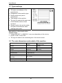
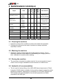
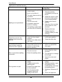
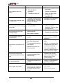
User Manual
Malfunctions and their remedy
Disturbance
Cause
1. Protective net for splitting
chute is open.
2. No oil or too little oil.
3. The valve has moved out
of position.
4. Debris inside the launch
system.
Splitting is not operational.
5. The oil is too cold.
6. A hydraulic hose has
burst or is leaking.
7. The splitting system does
not move due to freezing.
Remedy
of
the
malfunction
1. Close the protective net.
2. Stop the machine
immediately and top up
the oil.
3. Adjust the valve so that
the launch takes place
in the centre-position.
4. Clean up the launch
system.
5. Allow the oil to circulate
at free-flow for a few
minutes.
6. Replace the hose.
7. Always clean the
machine when you stop
working.
Protective cover for the
splitting chute cannot be
opened.
The splitting movement
does not stop, when the
protective net is opened.
1. The release lever for the
cover is in the closedposition
2. Clean the slide rails.
2. Debris in the slide rails of
the cover.
1. The setting of the locking
device has moved out of
position or the locking
device is broken.
1. The oil is too cold.
2. The oil is too hot.
Slow or powerless splitting
movement.
1. Bring the release lever
to the open-position
3. Check the splitting valve.
1. Adjust the locking
device or replace the
faulty part.
1. Allow the oil to circulate
at free-flow for a few
minutes.
2. Top up the oil or change
the oil type.
3. Open the cover and
check.
The log does not split.
1. Incorrect position of the
wedge.
1. Adjust the height of the
wedge.
2. A large branch at the
splitting point.
2. Stop the machine, open
the splitting cover,
rotate the log, and close
the splitting cover.
3. Exceeds the upper limit
for the machine.
4. The oil pressure has
dropped; check the
setting of the valve.
34
3. Maximum thickness 45
cm.
4. Check the hydraulic
450
system.
The crosscut saw cuts
poorly.
1. The saw-chain is dull.
1.
2. The saw-bar is
damaged.
Sharpen or replace the
saw-chain.
2.
Change the saw-bar.
3. Feeding of chain oil.
3.
Check the level and
feeding of the
lubrication oil.
1. The bolts of the bearings 1. Straighten the saw-shaft
supporting the saw-shaft
and tighten the bolts.
The saw-chain clashes with
have loosened. The sawthe saw-cover.
shaft in an oblique
position.
1. The setting has moved
1. Adjust the return roller
The conveyor belt is running
out of position.
at the end of the
at the side.
conveyor. Test run after
the adjustment.
1. Incorrect length of
1. Extend the stroke.
The log gets stuck in the
splitting stroke.
2. Sharpen the saw-blade.
splitting wedge.
2. Blunt splitting wedge.
The log clashes with the
conveyor belt.
1. The conveyor stands too
upright.
1. Emergency stop button
has been depressed.
The electric motor does not
start.
2. The temperature switch
has tripped.
3. Makes loud noise, but
does not start.
1. Low supply voltage.
The electric motor stops
easily and the thermo-relay
trips.
The electric motor rotates in
the wrong direction.
The oil gets very warm.
2. Incorrect setting of the
thermo-relay.
1. The extension cord
changes the direction of
rotation.
1. Too little oil.
2. The cylinder hits the
bottom but the pressure
is not relieved, so the oil
circulates via the relief
valve.
35
1. Decrease the rise angle
of the conveyor (30-45
degrees).
1. Reset the emergency
stop.
2. Wait for 1-2 minutes; the
temperature switch then
resets automatically.
3. One of the phases is
missing, reset/change the
fuse in the main centre.
1. Call an electrician to
measure the current
value and readjust the
thermo-relay to the
correct setting.
1. Have the direction of
rotation in the extension
cord/plug changed.
1. Top up oil.
2. Adjust the cylinder stroke
and swing.
3. Check the oil pump.
User Manual
9.5 Notes
36