1
BTnode Programming
— An Introduction to BTnut Applications
Number 1.5
Jan Beutel, Philipp Blum, Matthias Dyer
Clemens Moser, Mustafa Yücel, Philipp Stadelmann
Computer Engineering and Networks Laboratory
ETH Zurich
8092 Zurich, Switzerland
{beutel,blum,dyer,moser,yuecel}@tik.ee.ethz.ch
with contributions by
Marc Langheinrich, Jonas Wolf
Institute for Pervasive Computing
ETH Zurich
8092 Zurich, Switzerland
{langhein,wolfj}@inf.ethz.ch
The BTnode Project
January 22, 2007
ii
iii
CONTENTS
Contents
1 Introduction
1
1.1
The BTnodes and the BTnut System Software . . . . . . . . . . . . . . . . . . . . . . . . . . .
1
1.2
Intended Audience . . . . . . . . . . . . . . . . . . . . . . . . . . . . . . . . . . . . . . . . . .
2
1.3
Hard- and Software Requirements . . . . . . . . . . . . . . . . . . . . . . . . . . . . . . . . . .
2
1.4
Reference Documents
. . . . . . . . . . . . . . . . . . . . . . . . . . . . . . . . . . . . . . . .
3
1.5
Tutorial Overview . . . . . . . . . . . . . . . . . . . . . . . . . . . . . . . . . . . . . . . . . .
4
2 First Steps in BTnode Programming
5
2.1
Introduction . . . . . . . . . . . . . . . . . . . . . . . . . . . . . . . . . . . . . . . . . . . . . .
5
2.2
Development Tools . . . . . . . . . . . . . . . . . . . . . . . . . . . . . . . . . . . . . . . . . .
5
2.2.1
Compilation . . . . . . . . . . . . . . . . . . . . . . . . . . . . . . . . . . . . . . . . . .
5
2.2.2
Simulation and Debugging . . . . . . . . . . . . . . . . . . . . . . . . . . . . . . . . . .
6
2.2.3
Project Management . . . . . . . . . . . . . . . . . . . . . . . . . . . . . . . . . . . . .
6
2.2.4
Embedded Target Connection . . . . . . . . . . . . . . . . . . . . . . . . . . . . . . . .
6
2.2.5
Documentation Tools . . . . . . . . . . . . . . . . . . . . . . . . . . . . . . . . . . . .
6
2.3
Notes on the BTnode Hardware Architecture . . . . . . . . . . . . . . . . . . . . . . . . . . .
7
2.4
BTnut System Software Resources . . . . . . . . . . . . . . . . . . . . . . . . . . . . . . . . .
9
2.5
First steps in BTnode programming – Using the avr-gcc toolchain . . . . . . . . . . . . . . . .
12
3 Device-Level Programming
19
3.1
Introduction . . . . . . . . . . . . . . . . . . . . . . . . . . . . . . . . . . . . . . . . . . . . . .
19
3.2
Off-chip resource: Setting and Clearing LEDs . . . . . . . . . . . . . . . . . . . . . . . . . . .
19
3.3
On-chip resource: The Analog to Digital Converter . . . . . . . . . . . . . . . . . . . . . . . .
21
3.4
Writing interrupt routines: Hardware Timers . . . . . . . . . . . . . . . . . . . . . . . . . . .
22
3.5
Protecting shared data and resources . . . . . . . . . . . . . . . . . . . . . . . . . . . . . . . .
23
4 The BTnut Operating System
27
4.1
Introduction . . . . . . . . . . . . . . . . . . . . . . . . . . . . . . . . . . . . . . . . . . . . . .
27
4.2
Anatomy of a BTnut Program . . . . . . . . . . . . . . . . . . . . . . . . . . . . . . . . . . . .
27
4.3
The Terminal . . . . . . . . . . . . . . . . . . . . . . . . . . . . . . . . . . . . . . . . . . . . .
29
4.4
Timers . . . . . . . . . . . . . . . . . . . . . . . . . . . . . . . . . . . . . . . . . . . . . . . . .
31
4.5
Dynamic Memory Management . . . . . . . . . . . . . . . . . . . . . . . . . . . . . . . . . . .
32
iv
CONTENTS
5 Programming with Threads
33
5.1
Introduction . . . . . . . . . . . . . . . . . . . . . . . . . . . . . . . . . . . . . . . . . . . . . .
33
5.2
Creating Threads . . . . . . . . . . . . . . . . . . . . . . . . . . . . . . . . . . . . . . . . . . .
33
5.3
Thread Control . . . . . . . . . . . . . . . . . . . . . . . . . . . . . . . . . . . . . . . . . . . .
35
5.4
Sharing Resources: Mutual Exclusion (Mutex) . . . . . . . . . . . . . . . . . . . . . . . . . .
37
5.5
Events . . . . . . . . . . . . . . . . . . . . . . . . . . . . . . . . . . . . . . . . . . . . . . . . .
39
6 Embedded Debugging
41
6.1
Introduction . . . . . . . . . . . . . . . . . . . . . . . . . . . . . . . . . . . . . . . . . . . . . .
41
6.2
Tools . . . . . . . . . . . . . . . . . . . . . . . . . . . . . . . . . . . . . . . . . . . . . . . . . .
41
6.3
Debugging Techniques for the BTnode . . . . . . . . . . . . . . . . . . . . . . . . . . . . . . .
42
6.4
AVR Simulation . . . . . . . . . . . . . . . . . . . . . . . . . . . . . . . . . . . . . . . . . . .
43
6.5
The OS-Tracer . . . . . . . . . . . . . . . . . . . . . . . . . . . . . . . . . . . . . . . . . . . .
44
7 Communication Using Bluetooth
49
7.1
Introduction . . . . . . . . . . . . . . . . . . . . . . . . . . . . . . . . . . . . . . . . . . . . . .
49
7.2
Discovery of Bluetooth devices . . . . . . . . . . . . . . . . . . . . . . . . . . . . . . . . . . .
49
7.3
Creating Connections and Sending Data Packets . . . . . . . . . . . . . . . . . . . . . . . . .
53
8 Interfacing to Handheld Devices
57
8.1
Introduction . . . . . . . . . . . . . . . . . . . . . . . . . . . . . . . . . . . . . . . . . . . . . .
57
8.2
RFCOMM . . . . . . . . . . . . . . . . . . . . . . . . . . . . . . . . . . . . . . . . . . . . . . .
57
8.3
AT Commands . . . . . . . . . . . . . . . . . . . . . . . . . . . . . . . . . . . . . . . . . . . .
60
8.4
Sending an SMS Message using AT Commands . . . . . . . . . . . . . . . . . . . . . . . . . .
63
9 The Chipcon Radio
67
9.1
Introduction . . . . . . . . . . . . . . . . . . . . . . . . . . . . . . . . . . . . . . . . . . . . . .
67
9.2
Accessing the CC1000 . . . . . . . . . . . . . . . . . . . . . . . . . . . . . . . . . . . . . . . .
67
9.2.1
Initialization . . . . . . . . . . . . . . . . . . . . . . . . . . . . . . . . . . . . . . . . .
68
9.2.2
Sending Data . . . . . . . . . . . . . . . . . . . . . . . . . . . . . . . . . . . . . . . . .
69
9.2.3
Receiving Data – The ccc_rec Receiver Thread . . . . . . . . . . . . . . . . . . . . .
71
Advanced Topics . . . . . . . . . . . . . . . . . . . . . . . . . . . . . . . . . . . . . . . . . . .
72
9.3.1
Power Control . . . . . . . . . . . . . . . . . . . . . . . . . . . . . . . . . . . . . . . .
72
9.3.2
Frequency Control . . . . . . . . . . . . . . . . . . . . . . . . . . . . . . . . . . . . . .
73
9.3.3
Measuring Signal Strength . . . . . . . . . . . . . . . . . . . . . . . . . . . . . . . . . .
74
9.3
10 BTnodes and Sensors
75
10.1 ATmega128L I/O-Ports and Registers . . . . . . . . . . . . . . . . . . . . . . . . . . . . . . .
76
10.2 Sensor Types . . . . . . . . . . . . . . . . . . . . . . . . . . . . . . . . . . . . . . . . . . . . .
77
2
10.2.1 Digital I C-Bus Sensors . . . . . . . . . . . . . . . . . . . . . . . . . . . . . . . . . . .
77
10.2.2 Digital Logic-Level Sensors . . . . . . . . . . . . . . . . . . . . . . . . . . . . . . . . .
79
10.2.3 Analog Sensors . . . . . . . . . . . . . . . . . . . . . . . . . . . . . . . . . . . . . . . .
79
10.3 Reading Sensor Data . . . . . . . . . . . . . . . . . . . . . . . . . . . . . . . . . . . . . . . . .
81
v
CONTENTS
10.3.1 Polling . . . . . . . . . . . . . . . . . . . . . . . . . . . . . . . . . . . . . . . . . . . . .
81
10.3.2 Interrupts . . . . . . . . . . . . . . . . . . . . . . . . . . . . . . . . . . . . . . . . . . .
81
10.3.3 Hardware Timers and Actuators . . . . . . . . . . . . . . . . . . . . . . . . . . . . . .
83
10.4 The btsense-library . . . . . . . . . . . . . . . . . . . . . . . . . . . . . . . . . . . . . . . . .
86
A Software Versions Used
89
B Solutions
91
Date
Mar 2, 2005
Mar 24, 2005
Mar 30, 2005
May 10, 2005
May 12, 2005
Mar 21, 2006
Mar 24, 2006
Apr 5, 2006
Apr 5, 2006
Apr 6, 2006
Apr 19, 2006
May 29, 2006
Nov 13, 2006
Jan 08, 2007
Jan 15, 2007
Jan 17, 2007
Jan 22, 2007
Section
2, 3
3
1, 6
all
1
1,2,appendix
2
1,2,4,appendix
1
2
6
7
9,10
all
all
Who
jb
jb, pb
jb
jb, cm
jb, cm, md
jb
jb
jw
jb
ml
jb
jb, cm
my
jb
jb
my
Changes
Initial Version 0.1
Initial drafts of 2st and 2nd exercise done
Added input from beta-testers, ready for distribution
Edits after Clemens first import, added BTnode developer kit to introduction
Fixed graphics and rest of 5 and 6, prep for first release
Minor updates
Finished chapter 1 and 2 draft for SS2006
Added bootloader
Minor changes to chapter 2. Checked all solutions and moved some files around
Added Marc’s superb introduction modification
Replaced 115200 by 57600 (default baudrate)
Bluetooth updates for 2006, created version 1.3
Added chapter 7
Added chapters 9 & 10 by Marc Langheinrich
Added tutorial overview and changed solution numbering
complete review with minor changes
Version 1.5
Table 1: Revision History
1
Chapter 1
Introduction
1.1
The BTnodes and the BTnut System Software
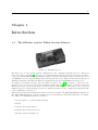
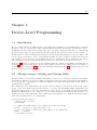
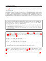
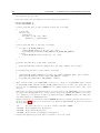
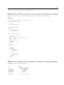
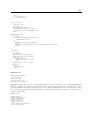
Figure 1.1: The BTnode rev3.
The BTnode is an autonomous wireless communication and computing platform based on a Bluetooth
radio and a microcontroller [3]. It serves as a demonstration platform for research in mobile and ad-hoc
connected networks (MANETs) and distributed sensor networks. The BTnode has been jointly developed
at ETH Zurich by the Computer Engineering and Networks Laboratory (TIK) and the Research Group for
Distributed Systems. Currently, the BTnode is primarily used in the NCCR-MICS research projects.
In addition to its Bluetooth radio, the latest BTnode revision (rev3) [2] also features a low-power radio
identical to the one used on the Crossbow/Berkeley Mica2 Motes [8], allowing it to interact with both
Mica2-based nodes and previous, Bluetooth-only revisions of the BTnode. Both radios can be operated
simultaneously or be independently powered off completely when not in use, considerably reducing the idle
power consumption of the device.
BTnodes run an embedded systems OS from the open source domain, called Nut/OS. Nut/OS is designed for
the Atmel ATmega128 microcontroller (which is used on the BTnodes) and intentionally kept very simple.
According to the Nut/OS description, it features:
• Non preemptive cooperative multi-threading
• Events
• Periodic and one-shot timers
• Dynamic heap memory allocation
• Interrupt driven streaming I/O
2
CHAPTER 1. INTRODUCTION
In order to use Nut/OS on the BTnodes, a set of BTnode-specific drivers have been added, and in particular
a Bluetooth stack for its on-board Bluetooth radio. These three pieces form together the BTnut system
software or short BTnut.
In this tutorial, we will learn how to use the BTnut system software to deploy sensor node applications on
the BTnode wireless sensor node platform.
1.2
Intended Audience
This tutorial originated in the Embedded Systems lecture, a graduate course taught at the Department of
Information Technology and Electrical Engineering, ETH Zurich and a graduate course on Wireless Sensor
Network taught at the Department of Computer Science, ETH Zurich. It requires basic knowledge of Cprogramming and embedded systems and should give an overview of the capabilities of networked embedded
systems and their key properties. However, apart from its usage in the lecture, this tutorial provides a basic
introduction to programming on the BTnode platform, so it should also be beneficial to the occassional
computer scientist not versed in all things electrical.
Each chapter comes with a set of exercises that are supposed to get you accustomed to basic, everyday tasks
of an embedded engineer. The order in which the exercises are performed is not of crucial importance, and
whole chapters can be left out to suit the individual needs (e.g., computer scientists might want to skip
those concerning hardware issues). However, we suggest that you perform the exercises in the order given
to minimize unforeseen complications.
1.3
Hard- and Software Requirements
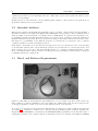
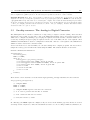
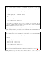
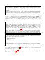
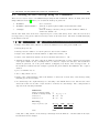
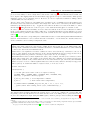
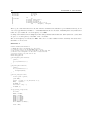
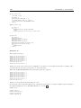
Figure 1.2: The BTnode development kit. The minimal set of tools consists of the three items on the very
right: a BTnode, a USB programming board, and a USB cable. Additionally, some exercises require the use
of an ISP programmer, a serial cable, and a 15-Pin Molex breakout cable (left half).
To be able to do all of the practical exercises in this tutorial, you will need a complete BTnode developer kit
(see Figure 1.2) consisting of: a BTnode rev3; a usbprog USB programming adapter; an ISP programmer (we
suggest the Atmel ATAVRISP or alternatively the ATAVRISP MK2 programmer); serial and USB cables; a
15-Pin Molex breakout cable; and the software, documentation and tools contained on the BTnode CDROM
3
1.4. REFERENCE DOCUMENTS
(see Figure 1.3). However, a number of exercises can also be performed with a minimal subset of these tools,
namely a BTnode, the USB programming adapter, and a USB cable.
For a complete listing of software tools and their respective versions used in this tutorial, please see appendix A. The tutorial assumes that the necessary development tools (avr-gcc toolchain, avr-libc, an ISP
programming utility if you use the ISP programmer, Eclipse and CDT) are installed and working correctly.
For details on the installation and configuration of the suggested development tools see the BTnode online
resources available at http://www.btnode.ethz.ch.
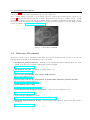
Figure 1.3: The BTnode CDROM.
1.4
Reference Documents
Should you ever need more information than what is given here in this tutorial, feel free to browse the
following sites for details on the individual pieces of the puzzle:
• The BTnode platform reference – with support documents, installation instructions for the development tools and source software, mailing lists and various links.
http://www.btnode.ethz.ch
• The home of Nut/OS – the BTnut operating system core.
http://www.ethernut.de
• Open source development tools for the AVR platform
http://www.openavr.com
• Open source tools for the development on Atmel AVR, Windows platform installer
http://winavr.sourceforge.net
• Atmel AVR product family
http://www.atmel.com/products/avr
• Atmel AVR related developer information – application notes, links and tools.
http://www.avrfreaks.net
• A nice avr-gcc tutorial (in german)
http://www.mikrocontroller.net/wiki/AVR-GCC-Tutorial
• Bluetooth Special Interest Group – all about the standardization, applications and reference
documents.
http://www.bluetooth.org
4
CHAPTER 1. INTRODUCTION
• Technical BTnode/BTnut support – For technical questions concerning BTnut and the BTnode
platform please inquire to the mailing list:
mailto:[email protected]
1.5
Tutorial Overview
Chapter 2 “First Steps in BTnode Programming” gives a basic introduction of development tools, software
structure and documentation sources necessary for development on the BTnode platform. Here we learn how
to program an Atmel AVR microcontroller using In-System Programming, compile our first program, use a
build system to automate compilation steps and manage software projects using eclipse and CVS.
The chapter 3 “Device Level Programming” introduces simple microcontroller programming and register
based input/output as well as interrupts. In chapter 4 “The BTnut Operating System” we introduce higher
level concepts of the BTnut operating system. Application structure as well as the terminal library, timers
and memory management are discussed. Threads are discussed in a separate chapter “Programming with
Threads” (chapter 5).
The chapter 6 “Embedded Debugging” is devoted to different techniques for the debugging and profiling of
larger applications where bugs are increasingly hard to find.
After the chapters on the basics about BTnodes and operating systems the remainder of the tutorial is
devoted to wireless sensor network application building using basic Bluetooth communication (chapter 7)
“Communication Using Bluetooth”), more advanced Blutooth communication with mobile phones in chapter 8
“Interfacing to Handheld Devices” and the usage of the “The Chipcon Radio” in chapter 9.
A short overview regarding “BTnodes and Sensors” is given in chapter 10 where you learn how to use the
generic extension interface of the BTnode to attach simple sensor boards and use them in BTnut applications.
5
Chapter 2
First Steps in BTnode Programming
2.1
Introduction
In this chapter, we will step you through the basic knowledge about development tools, software structure
and reference documentation necessary to start developing your own applications on the BTnode platform.
This is explained, using a pre-configured toolchain setup on Windows, although other host platforms and tool
setups are possible too (Linux and MacOS X). For detailed instructions on the tool installation, please refer
to the online documentation and links listed under section 1.4 and the software versions listed in appendix A.
2.2
Development Tools
For basic software development you will need an editor, a compiler-assembler-linker toolchain, a standard
library and an in-system programming software to upload the compiled program to your embedded target.
There are many other tools that can make life easier when projects are getting larger and debugging more
difficult. The selection of tools introduced here should provide you with a basic overview and understanding
to define the right set of tools for your personal project needs.
2.2.1
Compilation
The tools introduced here are freely available and are based on GNU GCC and the AVR libc which is a
Free Software project whose goal is to provide a high quality C library for use with GCC on Atmel AVR
microcontrollers. Together, avr-binutils, avr-gcc, and avr-libc form the heart of the Free Software toolchain
for the Atmel AVR microcontrollers. They are further accompanied by projects for in-system programming
software (uisp, avrdude), simulation (simulavr) and debugging (avr-gdb, avr-insight, AVaRICE).
These tools are available packaged as a Windows installer in the WinAVR project which we will use as
a reference. There are numerous other distributions of the avr-gcc toolchain available as well as different
(commercial) compilers for the Atmel AVR family.
A thorough introduction to the internals of such a compiler toolchain as used in embedded systems can
be found in Appendix A: Assemblers, Linkers and the SPM Simulator of [7]. Manuals for the avr-binutils,
avr-gcc and avr-libc are packaged with the respective distribution or available online (see section 1.4).
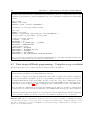
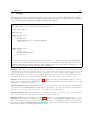
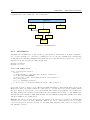
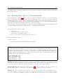
The following example illustrates a sample compilation, linkage with startup code and libraries as well as
transformation into a machine uploadable format of a sample application called test.c:
avr-gcc -c -mmcu=atmega128 -D__BTNODE3__-I../../include test.c -o test.btnode3.o
avr-gcc test.btnode3.o ../../lib/btnode3/nutinit.o -L../../lib/btnode3 -mmcu=atmega128 -o test.btnode3.elf
avr-size test.btnode3.elf
text
data
bss
dec
hex filename
36920
1708
314
38942
981e test.btnode3.elf
avr-objcopy -O ihex test.btnode3.elf test.btnode3.hex
6
2.2.2
CHAPTER 2. FIRST STEPS IN BTNODE PROGRAMMING
Simulation and Debugging
When project size increases and especially in critical situations specialized simulation and debugging tools
can be of great benefit. There are numerous tools available (avr-gdb, JTAG tools, Atmel AVR Studio, GNU
dwarf parser, avr-insight, Avrora, simulavr) serving different purposes, of which a selection will be introduced
in chapter 6.
2.2.3
Project Management
The basic utility used in most build environments is GNU make. The make utility automatically determines
which pieces of a large program need to be recompiled, and issues commands to recompile them. This is a
very convenient way to avoid retyping long lines of parameters on the command line.
Different editors with syntax higlighting and project management features can be used for C based AVR
development. The most common are Eclipse, Emacs, Programmers Notepad and AVR Studio. Especially
Eclipse in conjunction with CDT (C/C++ Development Tools) is a very powerful tool that allows C-indexing,
project management, integration of a make build environment, debugging, version control and much more.
Version control such as with CVS (Concurrent Version System) or Subversion is helpful for keeping track of
changes and sharing source code among team members.
2.2.4
Embedded Target Connection
The software on an embedded system is typically programmed once during manufacturing onto a resident
internal memory from where it is then executed. Software changes are frequent during development but
infrequent during the lifetime of a product.
For uploading code to the flash memory of the ATmega128l (in-system programming) a serial uploader
software (uisp, avrdude, uploader tools in AVR Studio) and an appropriate programmer (hardware) is
necessary.
Although basic debugging can be performed via general purpose IOs and LEDs, verbose terminal output is
generally preferred. For this a RS-232C serial connection is necessary between the embedded target (BTnode)
and a PC. This can be done using a serial level shifter (e.g. Maxim MAX3232) or a USB-serial converter
(e.g. Silabs CP2101).
In addition to uploading code using in-system programming as described above, the ATmega128l features a
bootloader section as well as JTAG uploading and debugging support (see chapter 6 for further information
on JTAG). The bootloader section in the flash memory can be used to re-program the user section of the
flash memory once such a bootloader has been installed. See exercise 2.14 for further information.
2.2.5
Documentation Tools
The primary source for information for any hard- or software system are its manuals, typically accompanied
by release information, changelogs, readme file and known errata.
The internet is a general resource for developers and project management. More specific mailing lists and
archives offer discussion forums on specific topics, such as the avr-libc library usage and development or on
BTnode specific issues.
Large online project management such as http://www.sourceforge.net offer many services such as electronic
bug tracking systems, version control, web visualization, nightly builds, software distribution and general
project management.
Single projects typically extract documentation from source code. This can be done by tools such as javadoc
or doxygen to automatically generate up-to-date online documentation.
7
2.3. NOTES ON THE BTNODE HARDWARE ARCHITECTURE
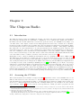
2.3
Notes on the BTnode Hardware Architecture
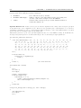
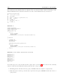
GPIO Analog Serial IO
Low-power
Radio
Bluetooth
System
ATmega128L
Microcontroller
SRAM
LED’s
Power Supply
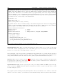
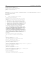
Figure 2.1: BTnode rev3 hardware overview.
System Core – The BTnode System Core consists of an Atmel ATmega128l microcontroller, clocks and
SRAM memory.
• Atmel ATmega128l – 4 kB EEPROM, 64 kB SRAM, 128 kB Flash
• System clock – 32 kHz real time clock and 7.3728 MHz system clock
• 5 processor power modes
• External data cache – 3x60 kByte low power SRAM
• Four LED’s for easy debugging
• In-system programming through serial ISP programmer, JTAG or resident bootloader
Bluetooth Radio – Zeevo ZV4002 Bluetooth radio running HCI firmware. It is connected to the ATmega128l through a UART interface.
Low-Power Radio – Chipcon CC1000 radio operating at 868 MHz. Other operating frequencies can be
used according to the CC1000 documentation (433-915 MHz). Both an integrated monopole antenna, an
external wire and an external coaxial connector (MMCX type) are possible though assembly options. The
default assembly variant is the internal monopole antenna and operation in the 868 MHz ISM band.
Power Supply – The standard power supply are 2-cell AA batteries. The common range for these is 2-3 V
DC when either primary or rechargeable batteries are used. The primary boost converter has a nominal
input range of 0.5-3.3 V DC. Alternatively 3.6-5 V can be supplied through the VDC_IN pin available on
the external connectors J1 and J2.
• Primary supply – Linear Technologies LTC3429, 600mA max., input 0.5-3.3 V to 3.3 V
• Alternate supply – Linear Technologies LT1962, 300mA max., input 3.6-5.0 V to 3.3 V
• Switchable power-groups for IO, Bluetooth and LPR radio
• Battery charge indicator
• On/Off switch for the primary power supply
A detailed hardware reference is available though the BTnode website (see section 1.4).
8
CHAPTER 2. FIRST STEPS IN BTNODE PROGRAMMING
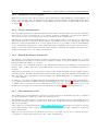
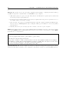
Figure 2.2: Atmel ATmega128l microcontroller core and peripheral block diagram.
Exercise 2.1. Find the BTnode rev3.20 Schematic and the ATmega128l Processor Manual pdf files [1].
Browse the schematic and find the latch (Texas Instruments SN74LVC573A) used to multiplex the extended
SRAMs (AMIC LP62S2048) data and address bus. Which ports of the processor are used to connect to the
latch? Which ports are used to connect to the memory?
Browse for the second latch used to multiplex the LEDs and switchable power supplies. Which port/pin on
the ATmega128l maps to which function (LED/power switches) here? Which are the control lines used for
the latch? Draw a sample output waveform for the microcontroller pins used, that switch the LEDs on and
off.
What are the problems arising from this hardware setup for a software system, especially in the case of an
operating system with concurrency (multiple drivers/tasks/threads)? How would you implement a software
driver for this functionality? Why is SBI/CBI (set bit and clear bit) not sufficient in this case?
2.4. BTNUT SYSTEM SOFTWARE RESOURCES
9
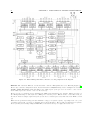
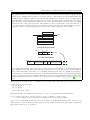
GND
UART0_CTS
UART0_RTS
UART0_TXD
UART0_RXD
PF0
PF1
SDA
SCL
PB4
PE6
PE3
VCC_IO
VCC
VDC_IN
1 GND
2 UART0_CTS
3 UART0_RTS
4 UART0_TXD
5 UARTO_RXD
6 UART1_CTS
7 UART1_RTS
8 UART1_TXD
9 UART1_RXD
10 PF0
11 PF1
12 SDA
13 SCL
14 PB4
15 RESET
16 GND
17 VDC_IN
18 VDC_IN
19 VCC_IO
20 VCC_IO
40 GND
39
38 TDO
37 TDI
36 TMS
35 TCK
34 RSSI
33 PDATA
32 PCLK
30 PALE
31 PE3
29 PE6
28 CHP_OUT
27 SS
26 SCK
25 MISO
24 MOSI
23 GND
22 VCC
21 VCC
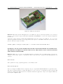
Figure 2.3: BTnode rev3 top assembly and connector pinout.
2.4
BTnut System Software Resources
First, we will make you familiar with the development environment and the tool flow. The exercises in this
section are based on using Eclipse and CDT, yet they can also be performed using other project management
environments and editors.
Explanation Getting to know the BTnut system software release:
The BTnut software is released in both a binary snapshot and sourcecode format. The most recent releases
can be downloaded from sourceforge.net.
• The btnode_snap_btnode3_binary contains an out-of-the-box pre-compiled library package for AVR
binary and documentation, ready for usage with the avr-gcc toolchain and the demo applications
included.
• The package btnut_system contains all BTnut and Nut/OS sources. It requires to compile the BTnut
system software and install the documentation prior to the compilation of applications.
The releases are numbered even and are based on the following CVS tag and date:
BTnut snapshot and release -- REL_VERSION = 1.8
Nut/OS -- NUT_SNAPSHOT = 2007-01-23
and compiles against the following avr libc:
AVR Libc -- avr-libc 1.4.3
The BTnut pre-compiled snapshot contains 5 directories, app for the applications, doc for documentation,
extras for hardware specific drivers other than the BTnode, include for all headerfiles and lib for the
pre-compiled libraries.
10
CHAPTER 2. FIRST STEPS IN BTNODE PROGRAMMING
The first task to be performed on the BTnut system software will be to set up a working environment within
Eclipse.
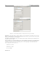
Exercise 2.2. Open the C/C++ perspective in Eclipse. Create a new project called btnut_snap_X.X by
selecting “Standard Make C Project” from the pull-down menu. Be sure to set the correct binary parser on the
second screen of the new project wizard (select ELF parser and GNU ELF parser, and enter avr-addr2line
and avr-c++filt) and set the correct compiler (avr-gcc) in the discovery options tab to select the correct
cross-development tools for the AVR platform.
Now import the btnode_snap_btnode3_binary package by selecting Import, Archive File into this project.
As a final task, you will need to configure the project with the correct include paths for the C/C++ parser:
Open the project properties and insert the btnut_snap/include, $(PATH_TO_AVR_GCC_TOOLS)/avr/include
and $(PATH_TO_AVR_GCC_TOOLS)/lib/gcc/avr/3.4.5/include to the projects include paths.
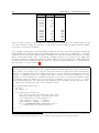
Exercise 2.3. Open the bt-cmd.c file in the app/bt-cmd folder and go to the line where btn_led_init(1);
is called. Highlight the function name, then press F3 to open the functions Declaration from the appropriate
header file. Right click the function name again and search for All References in the Workspace.
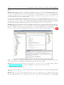
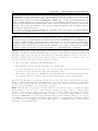
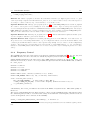
Be sure to switch to the C/C++ Perspective in Eclipse and open the C/C++ Projects View (see figure 2.4).
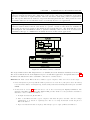
Figure 2.4: The C/C++ perspective with the C/C++ Projects view on the left, a file editor in the top,
console view in the bottom middle and the Make Target view open on the right.
Exercise 2.4. Open the BTnut System Software Reference (an online version of the BTnut API is available
on http://www.btnode.ethz.ch, or locally in doc/html) in a web browser and open the file
btnode/include/led/btn-led.h
from the File List. Read the documentation provided for the btn_led_init() and btn_led_add_pattern()
functions.
Exercise 2.5. Go back to the bt-cmd.c file and add a new led pattern for the LED heartbeat using
btn_led_add_pattern in line 103. While typing the function name btn_led_add_pattern press CTRL-SPACE
2.4. BTNUT SYSTEM SOFTWARE RESOURCES
11
to invoke Eclipse’s Content Assist function and complete the line with the correct arguments to create a
dual blinking LED pattern using these parameters:
pattern = BTN_LED_PATTERN_HALF
arg = 0
speed = 10
nr = BTN_LED_INFINITE
Exercise 2.6. Check the documentation available in the datasheets, application notes, mailing list archives,
Nut/OS webpage, Avrfreaks forum, tool resources, etc... to get an overview on the different compilers,
libraries, programming variants and hardware programmers available for the Atmel AVR family.
Exercise 2.7. Open the avr-libc Manual (online version available on the avr-libc webpage). Find the mathematics functions in the avr-libc and check what functions are supported. Compare this selection to the CPU
description found in the ATmega128l Manual and the instruction set of the ATmega128l found in the AVR
Instruction Set Manual. Don’t forget to read the available footnotes to learn about device specific options.
Think about what functions you would like to use to implement certain algorithms. Why are function such
as tan() present, but simple multiply and divide operations are missing? How would you implement a fixed
point division or even floating point operations for the AVR?
In addition check the FAQ found in the avr-libc Manual Related Pages documentation (especially entry 2)
and the General Utilities Module of the avr-libc Manual for information on further functions like div(),
qsort and rand().
Are there other libraries and languages available for the AVR family? Search for possible solutions on the
web.
Optional Exercise 2.8. When linking an application for a microcontroller a startup or initialization code
needs to be integrated that controls the bootup and initialization procedure and sets the system into a default state after power-on. This behavior can be specifically controlled by a memory map and init sections.
For an introductory documentation of the most common compiler flags and build steps, read through the
Demo Projects Module in the avr-libc Manual.
This topic is very complex. So we will generally use a pre-configured set up from the BTnut build system to
integrate the (hardware dependant) correct startup code and memory map.
Optional Exercise 2.9. In addition to the ChangeLog and README files provided with the BTnut System
Software, the project management environment on http://sourceforge.net/projects/btnode has a Tracker and
Tasks section to track bugs, requests for enhancements (RFEs), support requests etc. Check these locations
to learn more about development issues and possible caveats. If you discover a bug either enter it into
sourceforge.net or post them on the BTnode mailing list.
Now you have gained an overview of the BTnut System Software, developing in Eclipse and know how to
navigate code and search for documentation.
12
CHAPTER 2. FIRST STEPS IN BTNODE PROGRAMMING
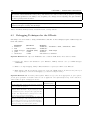
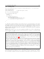
Explanation BTnut Configuration Options:
The BTnut System Software uses a GNU make based build system. The basic configuration is done in a file
Makerules and parameters are defined in Makedefs and can be overridden by setting them as environment
variables:
BURN = avrdude
BURNPORT = /dev/ttyS0
BURNFLAGS = -pm128 -cavrispv2 -P$(BURNPORT) -s
Alternatively you can use uisp with the settings:
BURN = uisp
BURNPORT = /dev/ttyS0
BURNFLAGS = -dprog=stk500 -dpart=atmega128 -dserial=$(BURNPORT) \\
--wr_fuse_e=0xFF --wr_fuse_h=0x00 --wr_fuse_l=0xBF
# Defines for btnode3 platform
MCU.BTNODE3
= atmega128
ARCH.BTNODE3 = avr
HWDEF.BTNODE3 = -D__HARVARD_ARCH__ -D__BTNODE3__
DEFS.BTNODE3 = $(HWDEF.BTNODE3)
# further define options
#DEFS.BTNODE3 += -DNUTTRACER
#DEFS.BTNODE3 += -DNUTTRACER_CRITICAL
#DEFS.BTNODE3 += -DNUTDEBUG
#DEFS.BTNODE3 += -DNUT_PERFMON
#DEFS.BTNODE3 += -DBT_L2CAP_SLIMDOWN -DBT_RFCOMM_SLIMDOWN
Here, you can select parameters for the default programming interface and define debugging verbosity. We
will make use of these features in later chapters of this tutorial.
2.5
First steps in BTnode programming – Using the avr-gcc toolchain
We will now use the tools to compile and upload a first program to the BTnode.
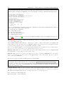
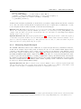
Explanation ISP Programming Variants: There are numerous software and hardware components
that allow ISP programming of an Atmel AVR microcontroller.
The default tool supported by Atmel is AVR Studio which offers a graphical user interface, simulation
and project management capabilities. To use it for programming of an AVR only, open the tool and select
the Program AVR entry from the Tools Menu. Be sure to select the correct device (ATmega128) in the
Program Tab, do not change the fuse bit settings and select the right Communications Settings (Auto)
in the Advanced Tab (see figure 2.5). When continuing from the command line be sure to close AVR Studio.
There are numerous command line tools for ISP programming as well. These are often more convenient than
the GUI based tools. In the following you will learn to use avrdude which also supports a GUI on windows.
For further informations such as using the bootloader function read the Atmel Applications Notes AVR109:
Self Programming, AVR910: In-System Programming and AVR911: AVR Open-source Programmer.
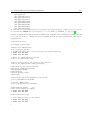
Exercise 2.10. Open a command line shell and check if your avr-gcc toolchain is installed and working
correctly. First check the versions of the avr-gcc toolchain by entering avr-as --version, avr-gcc -v and
avr-ld -v. Furthermore we will test avrdude -v (optional also uisp --version) that we will later use to
upload code to the ATmega128l.
2.5. FIRST STEPS IN BTNODE PROGRAMMING – USING THE AVR-GCC TOOLCHAIN
13
Figure 2.5: AVR Studio offers a graphical frontend to programming, simulation and project management
functions.
Optional Exercise 2.11. To see specific hints and help on the toolchain, execute the tools with the --help
parameter from the command line or the man pages (unix) to get detailed online help.
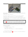
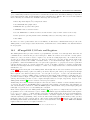
Exercise 2.12. Now connect a BTnode to your PC using a usbprog board and a USB cable (see figure 2.6).
Further connect an Atmel ATAVRISP programmer to the usbprog board and to a serial port on your PC.
The default settings are /dev/ttyS0 for programming through an ATAVRISP and /dev/ttyUSB0 for debugging through the serial port of the BTnode. (If in doubt about the right serial port for debugging use the
List_USB2UART script on windows or check /var/log/messages on linux.).
Try to communicate with the ATAVRISP and the ATmega128l on the BTnode:
avrdude -pm128 -cavrispv2 -P/dev/ttyS0
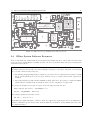
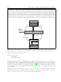
Explanation Using the USB-UART adapter board : The usbprog rev2 board is used for a breakout
of all pins available on connector J1. Furthermore it contains a USB to UART converter (Silabs CP2101)
that is used to connect the debug UART of the ATmega128l to a PC (default usage). A dedicated
connector for ISP programming is also available on the usbprog board. Also when using the USB
connection, the BTnode is remotely powered from the PC to save battery power.
Be sure to orient the usbprog board correctly as shown in figure 2.6. The board goes above the power
switch of the BTnode with the two mounting holes matching those on the BTnode. If in doubt about the
right serial port for debugging use the List_USB2UART script on windows or check /var/log/messages on
linux.
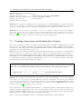
Exercise 2.13. Now upload a first pre-compiled application to your BTnode. Download the newest example
application file bt-cmd.btnode3.hex from the BTnode project sourceforge.net file release page. Open a command line shell. In this step you will two use avrdude commands that are executed by the ISP programmer:
erase and upload. First erase any programs present in the flash memory of the ATmega128l using erase:
14
CHAPTER 2. FIRST STEPS IN BTNODE PROGRAMMING
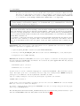
Figure 2.6: Debugging a BTnode using a USB connection to a serial port and ISP programming with the
Atmel ATAVRISP.
avrdude -pm128 -cavrispv2 -P/dev/ttyS0 -e
Then program the new application code from an Intel Hex file format to the BTnode using upload:
avrdude -pm128 -cavrispv2 -P/dev/ttyS0 -D -V -s -U flash:w:bt-cmd.btnode3.hex:i
The -D flag disables the auto-erase function, the -V flag disables auto-verify and the -s flag requires safemode.
You can add the -v flag to receive more verbose output. Observe the LEDs on the BTnode for output from
your first uploaded program.
Explanation Installing the bootloader : Download the newest bootloader file bootloader.btnode3.hex
from the BTnode project sourceforge.net file release page. To install the bootloader, proceed to upload this
program code to the BTnode using the ISP programmer as described analogously for bt-cmd.btnode3.hex
in exercise 2.13. Now your BTnode is ready to receive software flash reprogramming instructions.
To compile your own bootloader, navigate to the btnut_system/btnut/app/bootloader folder. Compile
the bootloader by executing make btnode3. You should now have a file called bootloader.btnode3.hex.
Optional Exercise 2.14. An alternative to using the ISP programmer is using a bootloader on the BTnode
that can emulate ISP behaviour. The bootloader may or may not be installed on your BTnode but can be
built from source code and installed using the method introduced in the previous exercise. See the explanation
box below for more information.
Now, to upload the program code:
1. press and hold the reset button on the BTnode
2. execute the upload command below
avrdude -pm128 -cavrisp -P/dev/ttyS0 -D -s -U flash:w:bt-cmd.btnode3.hex:i
3. release the reset button on the BTnode
If you can’t find the reset button, see figure 2.7. If you get strange error messages while programming, try to
disconnect and reconnect the USB cable.
2.5. FIRST STEPS IN BTNODE PROGRAMMING – USING THE AVR-GCC TOOLCHAIN
15
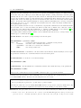
Figure 2.7: BTnode reset button
Exercise 2.15. Erase the bt-cmd application on the BTnode. Open a terminal programm to the serial port
you have connected your usbprog board with 57.6k, 8N1, no handshake to observe the terminal output from
the BTnode.
Upload the simple application uart-echo.btnode3.hex with uart output to the BTnode. As soon as the
uart-echo application responds, you can type and see the response on the LEDs. This time use the auto-erase
function and auto-verify on avrdude:
avrdude -pm128 -cavrispv2 -P/dev/ttyS0 -s -U flash:w:uart-echo.btnode3.hex:i
WARNING: DO NOT USE OTHER LOW-LEVEL COMMANDS WHEN IN-SYSTEM PROGRAMMING UNLESS YOU KNOW WHAT YOU ARE DOING AS IT COULD DAMAGE
THE MICROCONTROLLER!.
Exercise 2.16. Now go back to the bt-cmd application in Eclipse that we modified earlier and save the
changes we have made. Open a command line shell on this directory. Compile the bt-cmd application by
entering:
make btnode3
Then upload the newly compiled application to the BTnode with:
make btnode3 upload
Observe the different LED heartbeat compared to the pre-compiled bt-cmd.btnode3.hex we uploaded earlier.
Check the terminal program for output. Hit Tab twice to get a selection of commands possible in the bt-cmd
application. Explore the different functions available in this demo application. Try to locate different BTnodes
by issuing bt inquiry sync.
16
CHAPTER 2. FIRST STEPS IN BTNODE PROGRAMMING
Explanation The bt-cmd demo application: The bt-cmd demo application is a brief example of how
to use the Bluetooth radio and protocol stack. Once the application has booted and is ready on a serial
terminal with 57.6k, 8N1, no handshake you can check the list of available commands by hitting Tab twice.
# -----------------------------------------------------# Welcome to BTnut (c) 2006 ETH Zurich
# bt-cmd program version: 20060405-1206
# $Id: firststeps.tex,v 1.15 2007/01/22 16:40:02 beutel Exp $
# running @ 7.3628 MHz, NutFreq=1024l Hz
# ----------------------------------------------------booting Bluetooth module...
Bluetooth MAC address: 00:04:3f:00:00:d2
HCI version: 2 00C9 2 0012 003D
LMP features: 03 10 00 FF FF 05 F8 1B
Local name: ’ZeevoEmbeddedDevice’
hit tab twice for a list of commands
[bt-cmd@00:d2]$
bt
led
bat
nut
log
[bt-cmd@00:d2]$
There are NutOS/BTnode and Bluetooth specific commands (if called without arguments they will show
hints on the correct syntax, where applicable).
bt – bluetooth radio commands
led – toggle LED patterns
bat – get the battery status
nut – show OS system information
log – BTnut logging features
For reference on Bluetooth [6] see the support documents and links provided on the BTnode web-page (see
section 1.4).
Exercise 2.17. To simplify the building and uploading we will now create Make Targets in Eclipse that you
can execute with a single click.
Open the Make Targets View (Window → Show View → Other → Make) and navigate to the app/bt-cmd
folder. Right click onto this folder and select Add Make Target. Alternatively you can create different targets
by entering make arguments such as all, btnode3, version or clean.
Then use these Make Targets to automatically build and upload selected applications from within Eclipse.
You can observe the progress and console output from the respective views.
Exercise 2.18. Right click onto the bt-cmd.c file in the C/C++ Projects View and select Compare With
Local History to see the changes you have made earlier.
Exercise 2.19. Create a new folder in the app directory and copy the bt-cmd/Makefile to this folder.
Create (or alternatively copy and rename) a new application.c file in this folder. Be sure to edit the
project name in the Makefile.
Now you are ready to program your first own project using BTnut.
Explanation Resetting the work environment to initial conditions: The pre-compiled BTnut snapshot used in this tutorial can be obtained from http://sourceforge.net/projects/btnode, section Files. Download the btnut_snap_btnode3_binary_x.x.tar.gz file and unpack it to a location
of your choice. Now create a new Standard C/C++ Project in Eclipse and import the files from the
btnut_snap_avrbinary archive.
Optional Exercise 2.20. In order to stay up to date on the bleeding edge development codebase of BTnut
you will need to check out the most current version from the CVS repository on sourceforge.net. Open the
CVS Repository Exploring perspective in Eclipse and create a new CVS repository:
Host: btnode.cvs.sourceforge.net
Repository path: /cvsroot/btnode
2.5. FIRST STEPS IN BTNODE PROGRAMMING – USING THE AVR-GCC TOOLCHAIN
17
User: anonymous
Connection type: pserver
The check out the CVS HEAD of the module btnut as a Standard Make C Project. You can check for
changes to the most current CVS tag HEAD or to other dates and tags by selecting Compare With... or
Replace With....
Before building the demo applications in the app directory you will need to check out a release of Nut/OS
either by executing make nut_cvs_sources in the btnut directory or by checking it out from CVS into a parallel project as described above (host btnode.cvs.sourceforge.net, repositorqy /cvsroot/ethernut, module
nut. The build the BTnut libraries first by executing make clean and make all in the btnut directory.
18
CHAPTER 2. FIRST STEPS IN BTNODE PROGRAMMING
19
Chapter 3
Device-Level Programming
3.1
Introduction
The goal of this session is to familiarize the reader with some peculiarities of programming microcontrollers
that have a rich set of peripherals. After going through the tutorials and exercises, you should be able to
understand and write simple drivers which allow you to use these peripherals efficiently. To work through
the whole chapter takes you approximately four hours, without the optional exercises about two hours.
In this session, we will avoid using library functions and operating system support as far as possible. The
reason is that you should be able to really understand what is going on instead of using some black-box
functionality. Clearly, this type of programming is often a bit cumbersome. But you will enjoy the comfort
and convenience of an operating system that you will learn to use in the next session all the more.
In Section 3.2, the use of off-chip resources is explained using the example of the LEDs on the BTnodes. In
Section 3.3, the reader learns how to use the analog-digital converter of the ATmega128 as an example for
an on-chip resource. In Section 3.4, we introduce interrupts. The final Section 3.5 deals with critical sections
that are required to protect shared data.
3.2
Off-chip resource: Setting and Clearing LEDs
As a first example, we now use the LEDs on the BTnode. The reason for this choice is that for any further
work with the BTnodes, we need some kind of feedback from the programs we implement. The LEDs are
an off-chip resource. Unfortunately, accessing the LEDs is a bit tricky and requires some “hacks”, which are
explained in the following.
The address bus of the ATmega128 is 16 bit wide and it is mapped to the ports A (lower 8 bits) and C
(upper 8 bits). The address bus is mainly needed to access the external SRAM (AMIC_LP62S2048), but
at the same time it is also connected to the LEDs via a latch. To set or clear LEDs, the bits that determine
whether the LEDs should be on or off have to be put on the address bus. Then the latch is enabled, i.e. it
samples the value on the address bus. After a while, the latch is disabled, i.e. it holds the previously samples
value. The following function does exactly this:
void write_led(u_char value) {
volatile u_char * pointer;
u_char dummy;
// compute the pseudo-address that contains the values for the LEDs
pointer = (u_char *) ( ((u_short)value) << 8);
// force the compiler to write this pseudo-address to the address-bus
dummy
= *pointer;
// now enable the latch
20
CHAPTER 3. DEVICE-LEVEL PROGRAMMING
PORTB |= 1<<PB5;
// wait a moment
asm volatile ("nop" ::);
// disable the latch, i.e. hold the value
PORTB &= ~(1<<PB5);
}
Explanation volatile: Note the keyword volatile before the declaration of pointer. It tells the compiler
that code lines containing pointer should not be optimized at all. This is necessary because the compiler
does not know anything about external off-chip resources like the LEDs. Thus it cannot understand why
we compute the variable dummy, which is never used afterwards. If volatile were omitted, the compiler
would simply ignore such “nonsense” statements.
Explanation Accessing special purpose registers:
The names of special purpose registers are defined in the hardware/btn-hardware.h header file and in
header files included therein. These names can be used like variables. For example you may read the
content of the PORTB register using
u_char current_portb = PORTB;
Similarly, you can write to such a register in the same way as you write to a variable, e.g.
PORTB = 0xff;
sets all bits of the PORTB register to one.
Most often however, you only want to read or write a single bit of a special purpose register. This can
be done by using the bitwise and / or operators. The names of individual bits are also defined in the
header files. But these names cannot be used like variables, they are simple aliases for the position of the
corresponding bit within a register. For example PB5 is an alias for 5 since the PB5 bit is the fifth bit within
the PORTB register (counted from the left starting with 0). Examples:
if (PORTB & (1<<PB5)) // checks whether the PB5 bit is set
PORTB |= 1<<PB5;
// sets the PB5 bit to one
PORTB &= ~(1<<PB5);
// clears the PB5 bit
Exercise 3.1. To check whether you have understood how LEDs are controlled, use the BTnode schematics
to figure out the value needed to switch on the blue LED. Explain the computation of pointer.
As a start, we write a program that blinks with the blue LED. The main routine thus looks as follows:
#include <hardware/btn-hardware.h>
int main(void) {
DDRB |= 1<<DDB5;
while (1) {
// toggle the blue LED
// wait a second
}
return 0;
}
Explanation Configuring the direction of IO ports:
The line before the infinite loop configures the fifth bit of the DDRB register. DDRB stands for Data
Direction Register of Port B and this operation declares the fifth pin of port B to operate as an output pin.
After this line, you are free to use the write_led function shown above. See pages 63ff in the ATmega128
manual for a detailed explanation.
3.3. ON-CHIP RESOURCE: THE ANALOG TO DIGITAL CONVERTER
21
Exercise 3.2. Complete now the program sketched above. In order to see what your program does, you will
have to implement a pause function. Do this using a loop that increments a counter variable.
Optional Exercise 3.3. Once your program is running, try to estimate the clock frequency of the ATmega128. Do this by counting the operations in the loop of your pause function. HINT: Look at the list file
(<program name>.lst) which has been created by the compiler. Even without understanding any assembler
at all you can find your function by searching for its name. You can identify the loop by looking at the labels
(“.L6:”, for example) and the branch instructions (“brlo .L6”, for example). Assume that all assembler
instructions take one cycle to execute.
3.3
On-chip resource: The Analog to Digital Converter
The ATmega128 microcontroller contains an on chip analog to digital converter (ADC), whose detailed
description can be found on pages 231 to 247 of the ATmega128 manual. As for all on-chip resources, the
ADC can be configured by writing to special purpose registers, its status and the conversion result can be
accessed by reading from special purpose registers. In the case of the ADC, the two 8 bit registers called
ADMUX and ADCSRA are used for configuration and status. The two 8 bit registers called ADCH and
ADCL are used to deliver the conversion result.
As we now know how to use the LEDs, we can start writing more complex programs. We now want to
sample the battery power and show the result using the LEDs. The solution should look as follows:
#include <hardware/btn-hardware.h>
int main(void) {
int battery_power;
DDRB |= 1<<DDB5;
while (1) {
battery_power = get_battery_voltage();
// if battery_power below 1000mV, switch on red LED
// if battery_power between 1000mV and 2000mV, switch on yellow LED
// if battery_power above 2000mV, switch on green LED
// wait a second
// switch on blue LED
// wait a second
}
return 0;
}
We now have a more detailed look at the function get_battery_voltage. Its skeleton looks as follows:
int get_battery_voltage(void) {
// configure ADMUX
ADMUX |= 1<<MUX0;
ADMUX |= 1<<MUX1;
// configure ADCSRA register such that the conversion
// is as slow as possible and the ADC is enabled
// start conversion and wait for result
// read (and convert ?) result
}
In a first step, the ADMUX register is configured. As you can see in the manual, page 244, all bits are cleared
at startup and we only have to write the bits which we want to be one. Looking at BTnode schematics, we
22
CHAPTER 3. DEVICE-LEVEL PROGRAMMING
see that the BAT_SENSE signal is connected to pin 3 of port F. From the manual, page 239 we know that this
pin is the third channel of the ADC and table 98 on page 244 tells us that we have to set the bits MUX1 and
MUX0 from the ADMUX register to sample the voltage from channel three. We leave the ADLAR bit cleared. The
REFS1 and REFS0 bits are left cleared because we use the external voltage reference connected to the AREF
pin of the ATmega128.
WARNING: DO NOT USE OTHER SETTINGS FOR THE REFSx BITS, IT COULD DESTROY THE MICROCONTROLLER!.
Exercise 3.4. Now its your turn to configure the ADCSRA register. For maximal precision, we want the
slowest conversion speed. We do not use interrupts and we want to do a single conversion.
After having configured the ADC, the conversion can be started. This is done setting the ADSC bit of the
ADCSRA register. This bit is automatically cleared when the conversion is completed. Wait for this condition
and then read the result from the ADCL and the ADCH register.
Determine the values you expect from the ADC for a battery voltage of 1 volt and 2 volts, knowing that
the reference voltage is 3300 millivolts, the ADC delivers 10 bit values and the BAT_SENSE signal is half the
battery voltage (see schematics).
HINT: If your conversion result is always zero, make sure that (i) you either have batteries in your BTnode
or you have connected the battery contacts to an external power supply and that (ii) the power switch is on (if
connected to the USB cable, the BTnode is also powered if this switch is off, but then the BAT_SENSE signal
is 0).
3.4
Writing interrupt routines: Hardware Timers
In this section, the program from the previous section is modified such that it periodically samples the
battery voltage in a timer interrupt routine. The advantage is that now the microcontroller can do other
work in parallel. The processor load created by the timer interrupt is measured using an IO pin and the
oscilloscope.
Explanation Hardware Timers:
Another type of on-chip resources are timers. In principle, timers are counters that are incremented
automatically. By the use of configuration registers, the speed of incrementing the timers can be adjusted
and whenever the timers overflow or reach a specified value, they trigger an interrupt.
Explanation Interrupt Service Routines (ISR):
Interrupts are used to execute a function, the so-called interrupt service routine. The normal program flow
(the main function, in our case) is interrupted and the interrupt service routine is executed. As soon as it
terminates, the normal program flow is resumed exactly at the position where it was interrupted.
Timer interrupts can thus be used to execute some periodic functionality without having to spend the whole
processing time on waiting. An example is shown here:
#include <hardware/btn-hardware.h>
#include <dev/irqreg.h>
static void timer3IRQ(void *arg) {
// switch on green led
}
int main(void) {
// register interrupt service routine
NutRegisterIrqHandler(&sig_OVERFLOW3, timer3IRQ, 0);
3.5. PROTECTING SHARED DATA AND RESOURCES
23
// configure the speed of the timer
TCCR3B |= 1<< CS30;
TCCR3B |= 1<< CS32;
// enable the interrupt at overflows of the timer
ETIMSK |= 1<< TOIE3;
while (1) {
// toggle the blue led
// wait a second
}
return 0;
}
In addition to the main routine, the interrupt service routine (ISR) timer3IRQ is defined. At the very begin
of main, timer3IRQ is registered as the service routine for the sig_OVERFLOW3 interrupt, that is for the event
that timer 3 overflows.
After registering the ISR, the timer is configured. The CS30 and CS32 bits of the TCCR3B register are set
to configure the speed of the timer. In this case, the timer is incremented every 1024 clock cycles (see page
135 of the manual). The timer does not have to be started, it is always active. However, the generation of
interrupts when the timer overflows has to be enabled. This is done by setting the TOIE3 bit of the ETIMSK
register.
Exercise 3.5. We now will modify the previous program, such that the battery power is sampled in a timer
ISR. Use timer 3 in such a way that the battery power is sampled approximately once every two seconds.
The ISR displays the sampled result on the LEDs, but in contrast to the previous program, it does not wait
and switch on the blue LED. HINT: To adjust the interval of the ISR, you can change the prescaler (CS3x
bits) and/or set the timer manually to a non-zero value after every overflow.
Optional Exercise 3.6. Modify the program from the previous exercise using the clear timer on compare
match (CTC) mode of the hardware timer, which is described on page 121 and 131ff. Also use the ISR to
display the result of the battery power sampling using the LEDs as in the previous example.
In a real-world program, often a large number of different interrupts are used to service multiple peripherals
at the same time. By default, interrupts are blocked while an ISR is executing, thus different interrupts can
block each other. Therefore the careful programmer aims at keeping ISRs as short as possible.
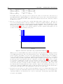
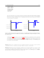
Optional Exercise 3.7. Measuring the execution time of an ISR can be done as follows: On a free IO
pin of the ATmega128, we generate a rising edge at the begin of the ISR and a falling edge at the end. The
time that the IO pin is high can then be measured on an oscilloscope. For example we may use pin 0 of port
F, which is a good choice since it is accessible as pin 6 on the 15-pin-connector of the BTnode, as you can
verify on the BTnode schematics. Connect this pin and ground (e.g. from pin 1 of the 15-pin-connector)
to the oscilloscope. Set up pin 0 of port F as an output pin using the DDRF register. How long takes your
ISR to execute? How much of the processing power is thus used for sampling the battery power every two
seconds? HINT: If you only have an analogue oscilloscope, you may have to decrease the interval of the
ISR drastically (e.g. 10ms is a good value) in order to display the generated waveform properly.
3.5
Protecting shared data and resources
In this section, the program from the previous section is extended to write measured data to the terminal.
It is explained why this should not be done from interrupt context. Thus the sampled data has to be shared
by the ISR, which determines the battery voltage and the main routine, which prints it to the terminal. It is
explained why this shared data has to be protected from uncoordinated concurrent access by multiple flows
of control and how this can be done.
24
CHAPTER 3. DEVICE-LEVEL PROGRAMMING
Explanation Using the terminal :
The ATmega128 has also two serial interfaces, so called Universal Asynchronous Receiver Transmitter
(UART) units. The UART1 is used to connect the ATmega128 to the Bluetooth module. The UART0 can
be used to write ASCII text to the terminal, which is a program running on the host computer. Writing
text to the terminal can be done using the well-known printf function from the avr-libc. Most standard
conversion strings (e.g. %d for signed integers) and special characters (e.g. \n) can be used, but not all.
For example the float conversion (%f) is not implemented.
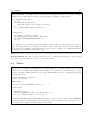
int variable = 13;
printf("Hello world, ");
printf("my lucky number is %d\n",variable);
The printf function writes a formatted string to the standard output stream. But before using printf,
we have to setup the standard output stream explicitly, that is we have to define that we want to link the
standard output to the UART0. This can be done using a routine like to following:
#include
#include
#include
#include
<hardware/btn-hardware.h>
<stdio.h>
<io.h>
<dev/usartavr.h>
// freopen
// _ioctl
// NutRegisterDevice, APP_UART, UART_SETSPEED
void init_stdout(void) {
u_long baud = 57600;
btn_hardware_init();
NutRegisterDevice(&APP_UART, 0, 0);
freopen(APP_UART.dev_name, "r+", stdout);
_ioctl(_fileno(stdout), UART_SETSPEED, &baud);
}
To read data from the terminal, you can use the function fscanf.
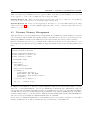
Optional Exercise 3.8. Write a program, that samples the battery voltage once every two seconds using
a timer ISR. Instead of displaying the result on the LEDs, print it to the terminal from within the ISR.
Measure the execution time of the ISR using the oscilloscope.
The measurement of the execution time of the ISR shows that printf takes a lot of time. We have discussed
before that ISRs should be as short as possible. Therefore we want to do the printing of the sampled battery
voltage from the main routine. Of course we want to print every measurement result exactly once.
Exercise 3.9. Rewrite the program from Ex. 3.8 such that the battery voltage is sampled in the ISR but that
the printing of the result is done in the main routine. To do this, you have to think about some communication
mechanism between the two flows of control.
Optional Exercise 3.10. Instead of printing the result from reading the ADCL and ADCH registers directly,
print it in millivolts. HINT: Remember that an unsigned short variable overflows at 65536, thus be careful
about the data types you use.
The program you have written probably works just fine. But if you would have a lot of time to observe its
behavior (or if you are “lucky”), you would notice that sometimes strange values are printed on the terminal.
3.5. PROTECTING SHARED DATA AND RESOURCES
25
Explanation Corruption of Unprotected Data:
If two flows of control, e.g. the main routine and an ISR access a piece of data, its value can become
corrupted. Assume that the ISR writes to a 16 bit variable which is read by the main routine. Assume
that its value at some point of time is 0x00ff. Now the main routine first reads the upper byte, that is
0x00, and then the ISR is executed. The ISR may increment the variable to 0x0100. After the ISR has
terminated, the main routine continuous reading the variable and reads the lower byte as 0x00. Now the
main routine has read the variable as 0x0000, which is far off the real value of either 0x00ff or 0x0100.
This problem can be solved by using critical sections, that is by protecting the access of a shared variable
in the main routine from being interrupted by an ISR. The other way round is no problem, since an ISR
cannot be interrupted by the main routine.
Explanation Enabling and Disabling Interrupts:
To protect a piece of code from being interrupted, you can disable interrupts globally using the function
cli(). To reenable interrupts, you can use the function sei(). These instructions clear and set the I-bit
of the SREG register, which is the main status register of the ATmega128 microcontroller.
Exercise 3.11. Protect the shared data that is used in your program from Ex. 3.8. Do this by implementing
the functions EnterCritical and ExitCritical. Make sure that ExitCritical does not enable interrupts
if they were disabled before EnterCritical.
Optional Exercise 3.12. Not all data access conflicts are so easily visible as the shared variable from
Ex. 3.8. For example our implementation of the write_led function has a problem of this kind too. Explain
why and fix it.
26
CHAPTER 3. DEVICE-LEVEL PROGRAMMING
27
Chapter 4
The BTnut Operating System
4.1
Introduction
In this chapter, we introduce the BTnut operating system (OS). In comparison to the exercises of the previous
chapter, this has two main consequences:
• You do not have to read hardware schematics and spec sheets when you want to use resources, since we
are now able to use library functions. In this chapter you will use such functions for accessing the LEDs
and the terminal. Also the analog to digital converter that we have used in the last chapter would be
accessible through such library functions – see the dev/adc.h header for a description. There is even a
function btn_bat_measure that does exactly what we have done manually (see hardware/btn-bat.h).
• Complicated programs can be divided into a set of threads. Programming a single thread is often much
easier than programming the whole functionality in a single program. At the same time, however, programming with multiple threads becomes more complicated. Even though the execution coordination
of these threads is done by the operating system, we still need to properly code concurrent threads,
especially when it comes to two or more threads using a common resource (e.g., the radio, or the terminal). Threads will be described in the following chapter, where we introduce the API of the BTnut
OS for creating, executing and terminating threads, as well as for the communication and coordination
of such threads.
The following sections will explain the anatomy of a simple BTnut program using the example of LED
control (section 4.2). Section 4.3 will then explain how we can use BTnut to provide output over a terminal
connection (i.e., through the USB cable).
4.2
Anatomy of a BTnut Program
Recall from chapter 1 that BTnodes run an embedded systems OS from the open source domain, called
Nut/OS. Nut/OS is designed (among others) for the Atmel ATmega128 microcontroller (which is used on the
BTnodes), and is thus an excellent base on which the BTnut extensions provide additional device drivers to
access BTnode-specific hardware. The actual compilation of your programs (i.e., the translation of C-code
into machine-code) is done using gcc-avr (part of WinAVR on Windows), which is a freeware C compiler
(and assembler) for the Atmel processor platform. We thus have three parts to our BTnode OS-experience:
the rudimentary C-libaries as implemented by gcc-avr’s avr-libc; the higher-level OS routines built on top
of avr-libc by Nut/OS; and the BTnode-specific device drivers provided by BTnut. In the following, we will
simply call this layered OS architecture “BTnut”, yet one should keep the differences in mind in order to
better understand the overall system operation.
We first look at a minimal BTnut program.
28
CHAPTER 4. THE BTNUT OPERATING SYSTEM
Explanation A minimal BTnut program: BTnut programs are written in C (though we don’t have
access to all libraries that we are used from our PCs). Just as any other C-Program, the feature a main
function as the initial focus of control, i.e., this is the first function that gets executed after power-up of
your BTnode. However, in contrast to regular PC programs, our BTnut programs must always begin with
initializing the BTnode hardware:
#include <hardware/btn-hardware.h> // for btn_hardware_init
int main(void)
{
/* ALWAYS call this func at the beginning of main */
btn_hardware_init();
/* initialize SRAM */
for(;;)
{
// do something clever here
}
/* main should never return (where to?!) */
}
Another peculiarity of a BTnut program is that it should never actually finish. In contrast to a PC program,
one cannot return to the command line after the execution of a particular application is done – BTnodes
are expected to continously execute their task! If their main program ends, the behavior of a BTnode is
undefined (it might simply restart, or stop altogether, or . . . ).
HINT: Do not put a return 0; or similar statement at the end of main, even though main is defined as
having an int return value. This allows the compiler to throw an error during compilation in case the last
line of your program should ever be reached (it shouldn’t, really!).
Obviously, an empty program is not very exciting. Let’s see how the LED control described in the previous
chapter can be implemented through BTnut OS function calls.
Explanation Using the on-board LEDs: BTnut OS offers through <led/btn-led.h> the functions
void btn_led_set (u_char nr) and void btn_led_clear (u_char nr), where nr denotes the LED in
question, namely 0 through 3. Before the LEDs can be controlled this way, we need to initialize them first:
#include <hardware/btn-hardware.h> // for btn_hardware_init
#include <led/btn-led.h>
// for led-related functions
int main(void)
{
btn_hardware_init();
btn_led_init (0);
btn_led_clear (0);
btn_led_clear (2);
/* initialize SRAM */
/* initialize LEDs */
btn_led_set (1);
btn_led_set (3);
for(;;);
/* endless loop */
/* main should never return (where to?!) */
}
Notice the argument that btn_led_init takes – it indicates whether we want to activate an LED heartbeat,
i.e., the periodic blinking of one or more LEDs to indicate that our BTnode is “alive” (as we didn’t want a
heartbeat in the above example, we used 0). For more information on LED heartbeats, see page 36.
Exercise 4.1. Write a program that endlessly rotates through the four LEDs (i.e., it turns one after another
on and off ). Observe the output. Use for statements to slow the rotation down until it becomes easily visible.
29
4.3. THE TERMINAL
Optional Exercise 4.2. Have your program from Ex. 4.1 terminate after a few rotations (you will need to
add return 0 to the end to get it to compile). What behavior do you observe?
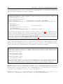
4.3
The Terminal
In order to communicate back to the user (or programmer), we are not restricted to using the on-board
LEDs only. Through our USB-cable, we can setup our BTnode in such a way that printf statements
provide output that can be printed in a terminal program on our PC, and use fscanf to read user input
from within the terminal program and input it back into our BTnut program. This is where the ATmega128
UART ports – Universal Asynchronous Receiver Transmitter – come into play. Actually, the ATmega128
supports USART ports – Universal Synchronous/Asynchronous Receiver/Transmitter. Consequently, you
will notice that some libaries and functions actually use usart in their names. However, as it does not make
much of a difference, and as UART is the much more common interface, we will continue to use that term.
The ATmega128 has two UART interfaces – UART0 and UART1. While UART0 is used to connect the
ATmega128 to the Bluetooth module, we can use UART1 to write ASCII text to the terminal, i.e., a program
running on the host computer that uses well-known communication protocols to send and receive text from
a remote computer. See the online documentation at http://www.btnode.ethz.ch for information on how
to setup a terminal program under Linux (e.g., minicom) or Windows (e.g., Hyperterm).
Explanation Setting up the terminal : The printf function writes a formatted string to the standard
output stream. But before using printf, we have to setup the standard output stream explicitly, i.e., we
have to define that we want to link the standard output to the UART1. This can be done using a routine
like to following:
#include <stdio.h>
#include <dev/usartavr.h>
// freopen, includes <io.h> for _ioctl
// NutRegisterDevice, APP_UART, UART_SETSPEED
void init_stdout(void) {
u_long baud = 57600;
NutRegisterDevice(&APP_UART, 0, 0);
freopen(APP_UART.dev_name, "r+", stdout);
// "r+": read+write
_ioctl(_fileno(stdout), UART_SETSPEED, &baud);
}
Once we have established a terminal connection, we can write text to it using the well-known printf function
(which is provided for the ATmega128 platform in avr-libc). Most standard conversion strings (e.g. %d for
signed integers) and special characters (e.g. \n) can be used, but not all. For example, the float conversion
(%f) is not implemented as the ATmega128 does not support floating point operations. HINT: Exit the
terminal program again before trying to upload a new program to the BTnode, otherwise the bootloader’s
upload replies will be caught by the terminal program, not your upload tool (i.e., the upload will fail).
int main(void)
{
btn_hardware_init();
/* initialize SRAM */
init_stdout();
int variable = 13;
printf("Hello world, ");
printf("my lucky number is %d\n",variable);
for (;;);
/* main should never return */
}
To read data from the terminal, you can use the function fscanf. However, in order to read input from the
user, we can use an already defined library – <terminal/btn-terminal.h> – which offers convenient access
30
CHAPTER 4. THE BTNUT OPERATING SYSTEM
to user input. Specifically, through the use of btn-terminal, a programmer can define a set of commands
and optional arguments that a user can execute from a terminal prompt. Upon hitting the Tab-key, the
BTnode terminal program lists all available commands.
Explanation
The
Interactive
Terminal :
The BTnode terminal is defined in
terminal/btn-terminal.h. After initializing it with the stream to use and prompt to display, the
programmer simply has to “run” it:
#include <hardware/btn-hardware.h>
#include <dev/usartavr.h>
#include <terminal/btn-terminal.h>
// NutRegisterDevice, APP_UART, UART_SETSPEED
// for interactive terminal, includes stdio.h and thus io.h
int main(void) {
btn_hardware_init();
init_stdout();
/* as defined above */
btn_terminal_init(stdout, "[btn3]> ");
printf("\nHowdy!\n");
btn_terminal_run(BTN_TERMINAL_NOFORK, 0); /* NOFORK never returns */
}
After the usual initializations (for an explanation of init_stdout, see page 29), the terminal thread is
initialized with btn_terminal_init, the first argument links it with the UART of the standard output
stream, the second argument defines the prompt of the command line (you may use any string you like).
Finally, the command btn_terminal_run(BTN_TERMINAL_NOFORK, 0) starts the terminal. The function
never returns, unless you use BTN_TERMINAL_FORK as the first parameter, in which case the terminal is
started in a separate thread. We will explain threads in chapter 5.
Using a terminal program such as minicom or Hyperterm, we can now interact with our BTnode program.
However, except for a small message and a prompt, there isn’t yet much we can do. Fortunately, BTnut
already comes with a few commands that we can readily make available in our terminal.
Explanation Predefined Terminal Commands: The BTnut OS offers sets of predefined terminal
commands. To use them, they have to be registered. Two of these sets, with the corresponding header file
and the register function, are given below. Similar command sets also exist for the bluetooth radio (bt_*)
and the debug logger (log_*).
#include <terminal/btn-cmds.h>
btn_cmds_register_cmds();
#include <terminal/nut-cmds.h>
nut_cmds_register_cmds();
The register commands have to be called after btn_terminal_init and before btn_terminal_run. For
example, btn_cmds_register_cmds provides the led command, nut_cmds_register_cmds provides the
nut command, which has several sub-commands. Hit the Tab-key for a list of available commands.
Exercise 4.3. Incorporate the default BTnut commands into your small terminal application. Use the nut
threads command to show the currently running threads. Now include led/btn-led.h and add a call to
btn_led_init(1) right after initialization. Also, add NutSleep(1000) to the final for-loop so that it isn’t
empty (this needs sys/timer.h). Observe the output of nut threads now.
Exercise 4.4. Change the call to btn_terminal_run to use BTN_TERMINAL_FORK as its first parameter (you
can leave the second argument “0” right now) and check the output of nut threads again.
4.4. TIMERS
31
Explanation Creating your own Terminal Commands: You can also register your own commands
with btn_terminal. You must provide a function with a standardized interface (a pointer to a single
argument of type char), which can then be registered under an arbitrary command name:
void _cmd_square(char* arg) {
int val;
if (sscanf(arg,"%d",&val)==1) {
printf("The square of %d is %d\n",val,val*val);
}
else { printf("USAGE: square <value>\n"); }
}
int main(void) {
...
btn_terminal_init(stdout, "[btn3]> ");
btn_terminal_register_cmd("square",_cmd_square);
btn_terminal_run(BTN_TERMINAL_NOFORK, 0);
for (;;);
}
The command square is registered with btn_terminal_register_cmd after the initialization of the terminal. The first parameter is the string you will have to type to launch the function, whose identifier is
given as the second argument. Note that functions that you want to register as a commands must have
the signature void <functionname>(char* arg).
Exercise 4.5. Write a program that registers the command echo, which simply echos all the given arguments.
Optional Exercise 4.6. Write a program that registers the commands myset and myclear, which will take
the numbers 0-3 as an argument, and set or clear the given LED.
4.4
Timers
Explanation Timers in BTnut: Instead of using for-loops or NutSleep calls, you can also use one
or more timers to schedule recurring function calls. Using timers, you can easily parallelize your program
without the need for explicit thread-management: simply create a function for each required aspect of your
program, and register different timers for each of them. BTnut will then take care of calling these functions
in the given intervals.
#include <hardware/btn-hardware.h>
#include <sys/timer.h>
HANDLE hTimer;
static void _tm_callback(HANDLE h, void* a) { . . . }
int main (void)
{
btn_hardware_init();
hTimer = NutTimerStart( 3000, _tm_callback, NULL, 0 );
for (;;) { NutSleep (1000); } /* never end */
}
You can use NutTimerStart and NutTimerStop to install or remove periodic timers. Using TM_ONESHOT
as the last parameter to NutTimerStart will automatically remove that timer after it has run once (i.e.,
after one interval) – using “0” instead installs a periodic timer.
32
CHAPTER 4. THE BTNUT OPERATING SYSTEM
Exercise 4.7. Write a program with two timed callback functions: one should repeatedly turn on the blue
LED (using btn_led_set(LED0)) and switch off the red LED (using btn_led_clear(LED1)), the other shall
do the opposite, i.e. turn on the red LED and switch off the blue LED.
Optional Exercise 4.8. Write a program that periodically calls a function to “shift” the current LED by
one position (after the last position, it should begin again with the first).
Optional Exercise 4.9. Create a terminal application that allows to control the LED shifting functionality
implemented in Ex. 4.8, i.e., use btn_terminal_register_cmd to create a command “toggle” that turns the
shifting on or off.
4.5
Dynamic Memory Management
Typically there is no need for dynamic memory management in your BTnode program. Simply create global
or local variables, and the BTnut OS (together with gcc-avr) will take care for you to properly allocate the
ATmega128 SRAM (of which we have 64kBytes) for the stack and the global and/or static variables.
However, should the need arise (e.g., you might want to limit the stack size of your current thread, or you
have temporary data that is very large), BTnut also supports dynamic memory allocation using malloc and
free.
Explanation Dynamic Memory Allocation: If you need to allocate memory directly, you can use
Nut/OS’s own malloc and free:
#include <hardware/btn-hardware.h>
#include <stdlib.h> // malloc, free
#include <string.h> // memset
u_int BUF_SIZE = 4096;
int main(void) {
char *buffer;
btn_hardware_init();
buffer = malloc(BUF_SIZE);
if (buffer) {
/* fill buffer with data */
memset(buffer, 0xFF, BUF_SIZE);
/* and free it again (really useful) */
free(buffer);
} else { /* out of memory */ }
for (;;);
/* endless loop */
}
In addition to the 64kBytes of directly accessible SRAM, the BTnode also features three banks of external
data cache – each having 60 kBytes – for a total of 180 kBytes of external storage. This memory cannot be
allocated directly from within our BTnut program, as our ATmega128 processor can only address 64 kBytes
of RAM. Instead, one has to briefly switch the upper 60 kBytes of our “regular” SRAM with one of the three
available banks, in order to access data in there. This functionality is implemented in the cdist/xbankdata.h
and can be tested by including the terminal/xbank-cmds.h commands.
See the sources of terminal/xbank-cmds.c in the btnut-sourcetree if you want to learn more about banked
memory. In this tutorial, we will not further elaborate on this feature of the BTnut OS.
33
Chapter 5
Programming with Threads
5.1
Introduction
In this chapter, we introduce thread programming with BTnut. A thread is simply a function or a small
program that can run concurrently to another thread. Using threads, we can actually write BTnode programs
that listen to incoming commands over their radio, periodically measure sensor values, compute intermediate
results, and send data to other nodes. All (virtually) at the same time!
This multithreading is handled by Nut/OS, as obviously our ATmega128 microcontroller can only handle
one instruction at a time. In order to support multithreading (or multitasking) on a single core processors,
the operating system needs to repeatedly start and stop individual threads (i.e., schedule) – in a completely
transparent fashion. Two general approaches to multithreading exist:
• Preemptive: The OS has complete control over processes and can stop, pause, and restart them (almost) at will. Most modern PC operating systems (e.g., Linux, Windows 2000/XP) use preemptive
multitasking. This is because it allows for a more reliable distribution of resources.
• Cooperative: Processes need to manually give up control of the CPU to a central scheduler, which
then evaluates which thread or task should come next based on process priorities and queues. While
cooperative multithreading simplifies resource sharing, and usually results in faster and smaller code
(making it thus more suited to embedded systems programming), it runs the risk that a poorly designed
or “hung” process can bring the entire system to a halt.
Nut/OS – and therefore also BTnut – employ cooperative multithreading. This means that in order to execute
two or more threads at the same time, each process needs to periodically give up control to the OS scheduler.
This will be described in more detail in section 5.3 below, right after we explain how to create our own threads
in section 5.2. Sections 5.4 and 5.5 finally introduce the concepts of mutexes and events, respectively, which
are means of coordination and communication between threads.
5.2
Creating Threads
Using BTnut, we can easily define and run our own threads. First we look at how threads are defined.
34
CHAPTER 5. PROGRAMMING WITH THREADS
Explanation Creating Threads: Threads are functions. As mentioned earlier, the main routine itself is
also a thread, which is started automatically after startup (fortunately, this is completely transparent to
the programmer, thanks to Nut/OS). Additional threads have to be declared using the THREAD macro. An
example defining the thread my_thread is shown below.
#include <sys/thread.h>
THREAD(my_thread, arg) {
for (;;) {
// do something
}
}
Functions that are used as threads are supposed to never return, thus to loop endlessly (if you want to
end a thread, you will need to manually call NutThreadExit). The second argument of the THREAD macro,
called arg here, is a void pointer and can be used to pass an argument of arbitrary type to the thread when
it is created (note that the actual declaration of arg as a void pointer is done by the macro). Don’t forget
to include <sys/thread.h> for working with threads!
The thread my_thread is now defined, but it has to be started before it becomes active.
Explanation Running Threads: A thread can be activated by any other thread, e.g. by the main
routine. This is done using the command NutThreadCreate.
#include <sys/thread.h>
int main(void) {
if (NutThreadCreate("My Thread", my_thread, 0, 192) == 0) {
// Creating the thread failed
}
for (;;) {
// do something
}
}
The first parameter defines a name for the thread, the second parameter is the name of the function we
have defined before. The third argument is a pointer that is passed to the thread function (compare with
the second argument arg of the THREAD macro) – we do not use this feature here and thus an arbitrary
value can be used. The last argument is the size of the stack that is allocated for the thread. This stack
is used for local variables and for passing arguments when calling subroutines. If this value is chosen too
large, the system may run out of heap memory. If it is chosen too small, the thread overwrites memory
that is used otherwise, which results in unpredictable behavior. See page 30 for a method to check whether
your stack size is correctly chosen. For now, just use 192 and you will be fine.
Exercise 5.1. Write a program that creates a thread as explained above. This thread shall repeatedly turn
on the blue LED (using btn_led_set(LED0)) and switch off the red LED (using btn_led_clear(LED1))
(HINT: LED0 and LED1 are just macros for the numbers we were using before, i.e., “0” and “1”, respectively.
However, using symbolic names instead of numbers makes our programs more portable). The main routine,
after having created the thread, shall do the opposite, i.e. turn on the red LED and switch off the blue LED.
Which LEDs are switched on? Why? Add a single NutThreadYield such that the other LED is switched
on. Add a second NutThreadYield, such that both LEDs are switched on by turns (you will see both LEDs
switched on, because the main routine and the thread alternate very quickly).
5.3. THREAD CONTROL
5.3
35
Thread Control
Exercise 5.1 has demonstrated the cooperative nature of the BTnut OS. In order to have two or more threads
running, they need to repeatedly and continously give up control of the CPU and other resources, so that
other threads may run.
In principle (we will see an exception later on), active (i.e., running) threads only yield the CPU to other
threads if this is explicitly coded. The most simple way to do this is NutThreadYield, a function that has
no parameters. This function causes the OS to check whether other threads with higher priority are ready
to run (we will explain thread priorities below). If this is the case, the current thread is suspended, i.e.
NutThreadYield does not return and the thread with the highest priority among those that are ready to run
is given the CPU. If no ready-to-run thread has a higher priority than the current thread, NutThreadYield
returns immediately.
Explanation Giving up Control : In order to support concurrent threads on the BTnode, each thread,
even the main() function, must periodically yield control. A call to NutThreadYield basically means “Is
there any process that is more important than myself? If so, feel free to take over control. Otherwise, I will
simply continue.” Once control has been given away and is returned at a later point in time, the thread
will continue to run right after the call of NutThreadYield.
If a thread has nothing to do, it can also force cease of control by calling NutSleep(time). This function
puts the current thread into SLEEPING mode and transfers control to any thread that is waiting for control
(i.e., is READY, see below). If no thread is waiting, the idle thread takes over, which is always ready-to-run
(but which has the lowest priority – see below).
Note that threads might also give up control involuntarily – in case of an interrupt. See the BTnut
documentation for details.
Explanation BTnut System Threads: We have already encountered a number of threads before,
created and run by the BTnut OS: the LED thread (see page 28 and excercise 4.3), the terminal thread
(see section 4.3 and excerise 4.4), as well as the idle thread and the main thread (again from exercises 4.3
and 4.4). We can visualize the currently active threads using the nut threads command (see Predefined
Terminal Commands on page 30):
[bt-cmd@00:d2]$ nut threads
Hndl
2057
14A4
1087
0D6A
Name
Prio Sta QUE Timr StkP FreeMem
T_TERMIN 150 RUN 0385 0000 200D
950 OK 2057 0D6A
LED
150 SLP 0000 2088 1481
989 OK
main
64 SLP 0000 2074 1064
733 OK
idle
254 RDY 0385 0000 0D4E
356 OK 2057 0D6A
In order to have all of these “standard” threats running at the same time, we also need to make sure that
all of them repeatedly yield the CPU to other threats. As the idle, LED, and terminal threat are all coded
for us by the OS programmers (who thoughtfully made all of these threats yield every so often), we only
need to make sure that the main threat (which is under our control) does so as well!
Exercise 5.2. Use the minimal BTnut program as described on page 28 and add a LED heartbeat (see page
28) and the predefined Nut/OS terminal commands (see page 30). Start the terminal in a new thread using
btn_terminal_run(BTN_TERMINAL_FORK, 0), but leave the main routine empty (i.e., use only for(;;)). Do
you see the LED heartbeat? Can you interact with the terminal? Fix your program so that both heartbeatand terminal-thread can be executed concurrently to your (empty) main program. HINT: See Ex. 4.3 and
4.4.
36
CHAPTER 5. PROGRAMMING WITH THREADS
Explanation Controlling the LED Thread : Initializing our LEDs with btn_led_init(1) also starts
a separate LED thread. The LED thread displays dynamic patterns on the LEDs, typically to indicate
that the program is still running (“heartbeat”). Its pattern can be set with a single command, i.e., using
btn_led_add_pattern or btn_led_heartbeat. See the BTnut system software reference for a detailed
description of these commands. By default, the LED thread starts to blink with the blue LED after
initialization.
Note that even when the heartbeat is active, we still can switch on and off LEDs individually using the
commands btn_led_set and btn_led_clear. The LED thread will remember the pattern it was showing
before LEDs are switched on manually and restart displaying the pattern after all these LEDs are cleared
again manually.
Exercise 5.3. Write a program with a main routine and an additional thread. Both threads repeatedly write
a message to the terminal and then yield (using NutThreadYield). What do you observe? (HINT: you
can freeze terminal output in minicom using Ctrl-A) Do you have an explanation? HINT: Writing to the
terminal is done with the speed of the UART, e.g., 57600 bits per second, which is slow in comparison to the
speed of the CPU. HINT No. 2: printf does not directly write to the UART, instead it writes to a buffer
with a limited capacity (default is 64 characters).
Explanation Thread Priorities and States: Each thread in BTnut has a priority – a value from 0–254.
The idle thread has the lowest possible priority, 254, while main, as well as all manually created threads,
have a default priority of 64.
Priorities become important if several threads are competing for control. Each thread can be in three
different states: RUNNING, READY, or SLEEPING. While only one thread can be RUNNING at any moment
in time (this is managed by the BTnut OS), several can either be READY or SLEEPING. A sleeping
process has ceded control either by calling NutSleep(time) (and is woken up by the OS after at least
time milliseconds have passed) or is waiting for an event (e.g., an incoming radio signal, or a message from
another thread – more about this in section 5.5 below).
Once the running thread cedes control using NutThreadYield, its state becomes READY, and BTnut
transfers control to another ready-to-run thread – the one with the highest priority. If all other ready-torun threads have a lower or at most equal priority, control is returned to the yielding thread immediately
(otherwise some unknown time later). Multiple threads with the same priority are executed in FIFO order.
Explanation Setting Thread Priorities: Remember that in the BTnut OS, threads have a priority in
the range of [0, 254], where a lower value means a higher priority. The default priority is 64. You may
assign the current thread a higher priority, e.g. 20, using
THREAD(my_thread, arg) {
NutThreadSetPriority(20);
for (;;) {
// do something
}
}
Note that changing the priority of a thread implies a NutThreadYield (i.e., setting its state to READY),
thus potentially yielding the CPU to another thread. This is the case if the running thread reduces its
priority, and is thus no longer the thread with the highest priority that is ready to run.
Exercise 5.4. Take the program from Ex. 5.1 and give the self-created threat a higher priority. Compare the
output with the original program from Ex. 5.1. Repeat the experiment giving the self-created thread a lower
priority. What do you observe?
Optional Exercise 5.5. Repeat Ex. 5.3 but give the additional thread a higher priority. Compare the output
with what you received in Ex. 5.3. Repeat the experiment giving the additional thread a lower priority. What
do you observe?
5.4. SHARING RESOURCES: MUTUAL EXCLUSION (MUTEX)
37
Optional Exercise 5.6. Repeat Ex. 5.3 but use NutSleep instead of NutThreadYield. Why is the output
different from Ex. 5.3?
Explanation Terminating Threads: A thread can terminate itself as shown below.
THREAD(my_thread, arg) {
for (;;) {
// do something
if (some condition)
NutThreadExit()
}
}
There is no easy way for some thread A to kill another thread B. Nevertheless, you will implement this
functionality in Ex. 5.13.
Combining thread creation with our means of writing command-line applications for the terminal (see section
4.3), we can experiment with thread creation and termination more conveniently:
Exercise 5.7. Write a program that registers the command create as a terminal command. This command takes a string argument and creates a thread with this name. This thread periodically prints its
name on the terminal and then sleeps for a second. HINT: A thread can access its own name using
runningThread->td_name, e.g., using printf("%s ready\n",runningThread->td_name).
Optional Exercise 5.8. Rewrite the program from Ex. 5.7 such that the first thread you start sleeps for
one second, the second thread sleeps for two seconds, etc. HINT: For this purpose, you may use the third
argument of the NutThreadCreate to pass the sleep time to the thread. Another alternative would be to use
a global data structure.
Optional Exercise 5.9. Rewrite the program from Ex. 5.7 so that the create command takes a second
parameter specifying the stack size of the thread that is created. Use this command and nut threads to figure
out how much stack is actually used by the threads you create. Add some local variables to these threads
and/or call some dummy functions from these threads to see how this increases the amount of used stack.
5.4
Sharing Resources: Mutual Exclusion (Mutex)
Ex. 5.3 showed the problem of two or more threads trying to access the same resource (the terminal)
concurrently. As a result, their output was garbled. One way to coordinate shared resources is the use of a
mutex – a lock mechanism for mutual exclusive resource usage.
38
CHAPTER 5. PROGRAMMING WITH THREADS
Explanation Mutexes in BTnut OS : Shared resources can be used exclusively by a thread by signaling current use over a mutex. After defining a mutex using NutMutexInit(&myMutex), threads can use
NutMutexLock and NutMutexUnlock to reserve the resource managed by the mutex:
#include
#include
#include
#include
#include
<hardware/btn-hardware.h>
<dev/usartavr.h>
// NutRegisterDevice, APP_UART, UART_SETSPEED
<stdio.h>
<io.h>
<sys/thread.h>
#include <sys/mutex.h>
MUTEX myTerminal;
THREAD(my_thread, arg) {
for (;;) {
NutMutexLock(&myTerminal);
printf ("This is Thread One\n");
NutMutexUnlock(&myTerminal);
NutThreadYield();
}
}
void init_stdout(void) {
. . . }
int main(void) {
btn_hardware_init();
NutMutexInit (&myTerminal);
init_stdout();
/* as defined previously */
if (0 == NutThreadCreate("ThreadOne", my_thread, 0, 192)) {
printf ("Sorry, could not create ThreadOne. Stopping...\n");
for (;;);
}
for (;;) {
NutMutexLock(&myTerminal);
printf ("This is the Main Thread\n");
NutMutexUnlock(&myTerminal);
NutThreadYield();
}
}
Exercise 5.10. Rewrite the program from Ex. 5.3 so that each thread first acquires a mutex lock before
printing to the terminal.
Exercise 5.11. Write your own little “thread-safe” printf function that uses mutexes in order to exclusively
acquire use of the terminal. HINT: You can either use a separate function call (e.g., my_printf) or a preprocessor macro (e.g., PRINTF). Using a macro should simplify argument handling, as gcc supports so-called
variadic macros:
#define PRINTF(...) {
/* acquire mutex */
printf (__VA_ARGS__)
/* release mutex */
}
\
\
\
\
5.5. EVENTS
5.5
39
Events
Another important part of a multithreaded OS is communication between threads. This allows the coordinated
use of multiple processes, as threads can signal other threads when to wake up, or in general inform a number
of threads that they have finished processing a particular data structure.
Explanation Sending and Receiving Events: The coordination (synchronization) of threads can be
done using BTnut events. Consider the example shown below:
#include <sys/event.h>
HANDLE my_event;
THREAD(thread_A, arg) {
for (;;) {
// some code
NutEventWait(&my_event, NUT_WAIT_INFINITE);
// some code
}
}
THREAD(thread_B, arg) {
for (;;) {
// some code
NutEventPost(&my_event);
// some code
}
}
Here we see two threads. Thread thread_A executes some code and then blocks in the NutEventWait
function. It only continues when either an event is posted or the timeout expires. The timeout is specified
in milliseconds with the second parameter. In the example shown above, the timeout is disabled, i.e. an
infinite time is specified with the macro NUT_WAIT_INFINITE.
Exercise 5.12. Write a program with three threads (main and two additional threads) and a global variable
with initial value 2. The three threads shall execute in turns, which you implement with events. One thread
computes the square of the global variable, the second decrements it by one and the third multiplies it by two.
All threads print the result on the terminal. When the global value has reached a value greater than 10000,
all threads except the main routine terminate themselves. The main routine enters an endless loop.
Exercise 5.13. Extend the program from Ex. 5.7 with the terminal command kill that takes the name of
a previously created thread as an argument. The terminal thread shall use an event to inform the selected
thread that it is supposed to kill itself.
Optional Exercise 5.14. What happens if first an event is posted by some thread A and only afterwards
some thread B does a NutEventWait ? What happens if multiple events are posted before another thread is
ready to receive them? Are the events stored or lost? Write a program to find out.
Optional Exercise 5.15. What happens if two threads are waiting for the same event? Are both threads
woken up? Do thread priorities play a role? Write a program to find out.
Exercise 5.16. Modify the program from Ex. 5.13 so that each created thread mostly sleeps (e.g., using
NutSleep(15000)) and only briefly listens for a kill signal (e.g., using NutEventWait(&killqueue, 125)).
Observe what happens if you send a process a kill signal. Does it eventually terminate? Try changing the
signal wait command to NutEventWaitNext(&killqueue, 125). Can you still terminate a thread with your
kill command? Why? Search the BTnut API for answers.
40
CHAPTER 5. PROGRAMMING WITH THREADS
Explanation Events Signaling in Nut/OS : When a signal is posted to an event queue (e.g., using NutEventPost), Nut/OS checks to see if any thread is waiting for a signal on this queue (using
NutEventWait). If there are threads waiting, Nut/OS takes the first thread only (i.e., the one with the
highest priority) and sets its status from SLEEPING to READY. Since posting events with NutEventPost
implies a NutThreadYield, the posting thread will also become READY. Depending on the priority of the
available ready-to-run-threads, Nut/OS might continue with the posting thread, switch to the signaled
thread (i.e., the one that was waiting), or even execute a completely different ready-to-run-thread with an
even higher priority than those two.
If you want to “wake up” all threads waiting on a particular queue, not just the one with the highest
priority, you can use NutEventBroadcast instead.
Explanation Asynchronous Events: When a thread posts a signal to a particular event queue using
NutEventPost or NutEventBroadcast, Nut/OS might switch control to another thread as these two function calls also imply a NutThreadYield (and thus a switch from the RUNNING state to the READY state).
In order to continue running, a thread may use so-called asynchronous variants of those two functions –
NutEventPostAsync and NutEventBroadcastAsync, respectively – in order to continue being in the RUNNING state. Both routines perform exactly the same signaling as their regular counterparts, yet without
executing a context switch. This can be done later using, e.g., a NutThreadYield or NutSleep.
Exercise 5.17. In order to gain understanding of threads and thread coordination, we will now write a ping
pong game. We have two players standing at opposing ends of a table that hit a ball back and forth, and
every time a player misses the table, the other player scores. The player that first reaches 11 points wins.
In order to implement this, we will need two players (0 and 1), one ball, and one coordinator (referee) that
keeps track of points. The sequence of events will look as follows:
1. The current player will play the ball (initially player 0).
2. The ball will move across the table, and either hit or miss the table.
3. In case the ball misses the table, the referee scores one point for the opponent. If this player has reached
11 points, the referee ends the game and declares this player winner.
4. The sequence repeats at point 1, with player 0 and 1 alternating turns. If the last ball missed the table,
the next player will serve, otherwise the point just continues until one player misses the table.
Implement this algorithm on the BTnode. All the actors in the game will be implemented as a separate
thread, coordination among threads is achieved through events. The coordinator records the score and outputs
messages to the terminal. After the game finishes, the program ends, but make sure the main method never
returns, otherwise the BTnode reboots and starts a new game!
HINT: The ball will be responsible for deciding whether or not it hits the table, i.e. whether the player
hits the ball well or not. In order to ‘decide’ whether a ball hits the table, we will use a random number
generator. At the beginning of the program, you will need to include stdlib.h and initialise the random
number generator by calling srand(u_int seed). From then on, every call to rand() will give a number
between 0 and RAND_MAX, so in order to get a random number r number between a and b (a <= r < b), use
a + rand() % (b-a). Experiment with different ‘player qualities’, i.e. using a higher probability of playing
a good ball and see how it influences the result. Make ample use of NutSleep in order to make the game
“watchable” on the terminal window.
41
Chapter 6
Embedded Debugging
6.1
Introduction
The goal of this tutorial is to get to know the different tools and techniques for embedded debugging
considering the BTnode platform as example.
One of the most compelling problems for anyone programming an embedded system, is to understand what
your system is doing, what resources it’s using and how it interacts with the external world. Bugs occur.
Fixing them is usually easier than finding them! The problem is that embedded code cannot be easily
executed under a debugger, nor can it be easily traced, because of the following circumstances:
• Embedded systems are resource constrained. Some debugging techniques might cause too much
overhead (processing, communication and memory). Applying debugging may obscure the real problem
(Heisenberg effect).
• The embedded processor is connected to peripheral hardware components such as A/D-converters,
timers, communication interfaces, interrupt controllers and general purpose I/O pins. The embedded
programm closely interacts with those components which makes it hard to trace.
• Embedded system often provide very limited access to the resources. If all you have is four LEDs,
debugging will be very hard.
6.2
Tools
Good mechanics have many tools; you can’t fix a car with just a hammer. Like good mechanics, good
programmers need to be proficient with a variety of tools. Each has a place; each has a Heisenberg effect;
each has power.1
Explanation Simulator with source-level debugger : A simulator allows for early debugging and
execution of algorithmic code. It does not require any target hardware. A source-level debugger lets you
step through your code, stop it, and then examine memory contents and program variables.
Explanation In-circuit emulator (ICE) and JTAG debugger : An Emulator emulates the behavior
of the real chip. ICEs allow you to replace the real chip that interacts with I/O components for better
insight. JTAG debuggers directly connect to the real chip instead of replacing it. ICEs and JTAG debuggers
can be used for source-level debugging.
1 The
ten secrets of embedded debugging: http://www.embedded.com/showArticle.jhtml?articleID=47208538
42
CHAPTER 6. EMBEDDED DEBUGGING
Explanation Simple printf statements: This is perhaps the most flexible and primitive tool. Printing
out variable values and function entry/exit points allows you to discover how your program is operating.
Unfortunately printf is both clumsy to use (requiring code changes and recompiling) and quite intrusive
because it greatly slows execution.
Explanation Operating system monitors: Operating system monitors display events, such as task
switches, semaphore activity and interrupts.
Others: Profilers, memory testers, execution tracers, coverage testers.
6.3
Debugging Techniques for the BTnode
Following tools can be used to debug an AVR microcontroller. Some techniques require additional special
hard- and software:
1
2
3
4
5
Technique
Simulator
ICE
JTAG debugger
printf
OS monitor
Hardware
–
ICE40/ICE50
JTAGICE (mkII)
UART
UART
Software
AVRStudio / AVaRICE + GDB / SimulAVR + GDB
AVRStudio
AVRStudio / AVR insight
Terminal
Nut OS Tracer, Terminal
Optional Exercise 6.1. Open the AVRStudio and consult the AVR Studio Tools and User Guide.
1. Compare the features and limitations of an Emulator (ICE50) with the ones of a JTAG debugger
(JTAGICE).
2. What is on-chip-debugging (OCD)? Which hardware is required for OCD on the BTnode?
3. What happens with the peripheral components of the µC (UART, Timers, A/D Converter) when you
enter stop-mode for source-level debugging (e.g. when a breakpoint is hit)?
Optional Exercise 6.2. Consider following table. Which tool(s) is/are most appropriate, in your opinion,
for the given problems? Sometimes all tools can be applied in order find and fix a bug. Some with more,
others with less effort. Justify your answer.
Problem
Tool:
Simulator/
JTAGICE/printf
An algorithm that operates from memory to memory
does not behave as expected.
The µC communicates over one of its hardware UART
with the Bluetooth module. In general, the µC sends
a command sequence and parses the reply from the
module. The implementation of this protocol on the
µC is erroneous and needs debugging...
You are implementing a network stack. A series of
function is called (for each network layer) to process
an incoming packet. In your current implementation,
when a packet is received, the µC freezes somewhere
in the processing. You want to find out where.
Reason
6.4. AVR SIMULATION
6.4
43
AVR Simulation
In this section you will learn how to use AVR simulation for prototyping and source-level debugging. We
introduce two simulators: simulavr and the AVR Studio Simulator. Unfortunately, both of them are quite
limited, i.e. they only simulate a subset of the AVR peripherals (timers, etc.). As a consequence, applications
that use Nut/OS can not be simulated. The simulator usually breaks in one of the timer interrupt routines.
Exercise 6.3. Simulavr + AVR-Insight In this exercise you will learn how to start simulavr and how
to connect the AVR-Insight debugger to it.
1. Create a new C file simpleio.c with the following code:
#include <io.h>
void delay(void){
int i;
for(i = 0; i < 1000; i++);
}
int main(void){
DDRF |= _BV(0);
for(;;){
PORTF |= _BV(0);
delay();
PORTF &= _BV(0);
delay();
}
}
2. Compile the file manually with the debug-symbols option (-g):
avr-gcc -mmcu=atmega128 -g -I/usr/pack/btnode-1.0-mo/avr/include/avr simpleio.c -o simpleio.elf
3. Start AVR-Insight:
avr-insight&
4. Start simulavr as a gdb-server:
simulavr -g -d atmega128
The simulator should print out something like: Waiting on port 1212 for gdb client to connect...
5. In order to connect Insight with the simulator, open the gdb-console (View→Console) and enter following commands:
file simpleio.elf
target remote localhost:1212
load
break main
continue
6. Congratulations: now you can step through your code, set breakpoints and watches.
Optional Exercise 6.4. AVR Studio Simulator
1. AVR Studio needs a different debug format. Compile the code from the last exercise with -gdwarf-2.
2. Open AVRStudio and open your .elf file from the File->Open File menu. A project wizard appears.
Select AVR Simulator as debug platform and ATmega128 as device.
3. The simulator initializes and stops at the first instruction. Go to the AVR Simulator Options from
the Debug menu, and set the frequency to 8.00 MHz.
44
CHAPTER 6. EMBEDDED DEBUGGING
4. In the I/O workspace window on the left side you find all the simulated resources of the AVR. Take
some time to browse through the individual items. Expand the PORTF item.
5. Congratulations: now you can step through your code (F10), set breakpoints and watch how the ports
and registers change in the workspace.
Optional Exercise 6.5. Profiling printf with AVR-Studio
Printf statements are often used for debugging. Printing out variable values and function entry/exit points
allows you to discover how your program is operating. In this exercise we measure the cycle count of an
example printf statement in order to get the feeling of the overhead.
1. Edit your "nutsim.c" file:
#include
#include
#include
#include
<io.h>
<stdio.h>
<dev/usartavr.h>
<hardware/btn-hardware.h>
int main(void) {
u_long baud = 57600;
btn_hardware_init();
NutRegisterDevice(&APP_UART, 0, 0);
freopen(APP_UART.dev_name, "w", stdout);
_ioctl(_fileno(stdout), UART_SETSPEED, &baud);
printf("UART baudrate = 57600\n");
for(;;);
}
2. Recompile the .elf file. The simulator should automatically restart and load the new file.
3. Step through the code until the yellow arrow is on the printf statement. Expand the processor item in
the I/O workspace. Remember the cycle count.
4. Proceed one step (step over). Compare the cycle counter with the previous values. How many cycles
did it take?
5. Normally printf statements have formatted output. Replace the existing printf statement with:
printf("UART baudrate = %u,%u kbaud\n",
(int)(baud / 1000UL),
(int)((baud - (baud / 1000UL)*1000UL)/100));
6. Compare the cycle count of the formatted printf with the unformatted one.
6.5
The OS-Tracer
Printf is often used for debugging. However, in the previous section, we have seen that this method has a
relatively large overhead. Thus, it is not suitable for tracing frequent events such as interrupts or thread
switches. For such events, the tracer tool is more appropriate.
6.5. THE OS-TRACER
45
Explanation Tracer Tool, Interactive Mode: The tracer tool stores information about important OS
events in memory and prints this information later on the terminal for analysis purposes. Important OS
events include thread switches (due to sleeps, yields, priority changes, etc.) and interrupts. In addition to
the type of event, the exact system time (microsecond resolution) and additional information (e.g. which
thread did a sleep) is stored.
The tracer tool can be used in various different ways. The most simple is the interactive terminal mode.
To activate the tool, use
#include <sys/tracer.h>
btn_terminal_register_cmd("trace",NutTraceTerminal)
as it has been explained in the previous section.
Preparation The current version of the btnut binaries does not flag OS events for the tracer. Therefore
the sources have to be recompiled with the -DNUTTRACER option.
1. Open the file Makedefs located in the folder btnut
2. Uncomment the line DEFS.BTNODE3 += -DNUTTRACER.
3. Recompile the sources (make clean install in folder btnut).
Exercise 6.6. This exercise is a step-by-step tutorial for using the trace tool. First write a program that
starts the LED thread, then registers the trace terminal command and then starts the terminal thread. Run
this program and continue as follows:
1. Type trace, you will get the output:
[es-ex3]$trace
TRACE STATUS
Mode is OFF
Size is 0
contains 0 elements
SYNTAX: trace [print [<size>]|oneshot|circular|size
<size>|stop|mask [<tag>]]
2. Type trace oneshot and then type trace again. If you have not waited too long between the two
commands, you will get something like this:
[es-ex3]$trace oneshot TRACE mode ONESHOT, restarted
[es-ex3]$trace TRACE STATUS
Mode is ONESHOT
Size is 500
contains 77 elements
SYNTAX: trace [print [<size>]|oneshot|circular|size
<size>|stop|mask [<tag>]]
Typing trace again will give you a similar status except that the contains XX elements shows an
increasing number. When it has reached 500, the Mode changes to OFF again as it was before we typed
trace oneshot, but now contains 0 elements is replaced by is full.
[es-ex3]$trace TRACE STATUS
Mode is OFF
Size is 500
is full
SYNTAX: trace [print [<size>]|oneshot|circular|size
<size>|stop|mask [<tag>]]
3. In the previous step, we have filled the trace buffer with events. We now can have a look at them by
typing trace print 10, which gives you an output like this:
[es-ex3]$trace print 10
TRACE contains 500 items, printing 10 items. TAG
PC/Info
Time [s:ms:us]
-----------------------------------------------
46
CHAPTER 6. EMBEDDED DEBUGGING
Thread Yield
idle
13:524:336
LED
13:524:604 Thread Yield
13:581:857 Thread Sleep
LED
Yield
idle
13:639:392 Thread
13:639:659 Thread Yield
idle
Sleep
LED
13:697:205 Thread
13:754:442 Thread Sleep
LED
Thread Sleep
idle
13:582:125 Thread
Sleep
LED
13:696:909 Thread
Yield
idle
13:754:710
In the TAG column, you see the type of the recorded events. In the case shown above, all events are of
type Thread Yield or Thread Sleep, the column Info shows you the name of the thread which has
done a sleep or a yield and the Time column indicates at what time this was done. The time is 0 when
the BTnode is booted.
4. The list of events does not allow you to quickly understand what is really going on. Therefore we
now use the terminal program on the host computer to capture the terminal output in a file. Then we
postprocess the trace file we have created in the previous step using Matlab. Thus start Matlab now. Type
show_trace(’<the filename of the captured terminal output>’), which opens a figure like the
one shown in Fig. 6.1. Be sure to use a separate log file for each trace captured. In this figure, you can
see time on x-axis and three threads on the y-axis.
main
idle
LED
0
2000
4000
6000
8000
Time [ms]
10000
12000
14000
Figure 6.1: Execution of threads for the program listed in Exercise 6.6.
What you can see is that the BTnode spends most of the time in the idle thread. Periodically, it switches
to the LED thread and a few times, the main thread was active. The LED thread is responsible for the
periodic blinking of the LEDs, it becomes active approximately every 60ms and takes about 300µs to
execute. The main thread is responsible for capturing terminal input and launching the corresponding
commands. Thus if you did not type trace while the buffer was filling, you will see only one spike to
the main line at the very beginning of the trace. Otherwise (as shown in Fig. 6.1) you can see a spike
for every letter of trace plus one when you pressed return. Parsing a keystroke takes about 600µs,
executing the command after pressing enter takes much longer, approximately 6ms. When looking
closely at the last spike, you may note that it actually consists of several spikes. This is due to the
fact, that the trace command prints the status of the trace buffer to the terminal, but cannot do so in
a single shot. It fills the UART buffer until it is full, then yields execution to the idle thread and is
woken up when the buffer has become empty again to write the rest of the output.
5. In the previous step we have seen, that even when the BTnode seems to do nothing really useful, several
threads are executed. To understand a little bit better how this actually works, we now do another trace
capturing in addition to the threads also the occurrence of interrupts. To this purpose type trace mask.
[es-ex3]$trace mask TRACEMASK
47
6.5. THE OS-TRACER
0 Critical Enter OFF
1 Critical Exit OFF
2 Thread
Yield ON
3 Thread
SetPrio ON
4 Thread
Wait ON
5 Thread
Sleep ON
6 Interrupt Enter OFF
7 Interrupt Exit OFF
8 Trace Start ON
9 Trace Stop ON
10 User * ON
You get a numbered list of event types followed by either ON or OFF. Typing trace mask 6 redisplays
this list, but now the event type 6, which is the begin of an interrupt service routine is set to ON. Repeat
this for the event type 7. Now take a trace as explained in the previous steps, capture the event list in
a file and display it using Matlab.
main
main
idle
idle
LED
LED
Int−UART0_TXEMPTY
Int−UART0_TXEMPTY
nt−UART0_RXCOMPL
I
nt−UART0_RXCOMPL
I
nt−TIMER0_OVERFL
I
nt−TIMER0_OVERFL
I
250.5
251
251.5
Time [ms]
252
516
516.5
517
Time [ms]
517.5
518
Figure 6.2: LED thread woken up by the timer interrupt. Left: LED thread woken up by the timer interrupt.
Right: Main thread woken up by UART receive interrupt, causing transmit complete interrupts by echoing
the terminal input.
Looking at Fig. 6.2, left side, you can see how the LED thread is triggered by the timer interrupt
(Int_TIMER0_OVERFL). On the right side of Fig. 6.2, it is shown that the main thread is activated after
the occurrence of a UART receive interrupt (Int_UART0_TXCOMPL). Since the main thread echoes all
received characters to the terminal, two UART transmit complete interrupts occur immediately after
the activation of the main thread.
Exercise 6.7. The traces captured in the previous example show that most of the time is spent in a thread
called idle, which was not started by our program. What is the purpose of this thread?
Exercise 6.8. When the tracing of interrupts is enabled, you can see timer interrupts. You can also see that
a thread that sleeps always awakes immediately after these timer interrupts. Figure out the interval of these
timer interrupts and think about what kind of restriction this implies for the NutSleep function. HINT:
Remember that you can specify the sleep time in milliseconds.
48
CHAPTER 6. EMBEDDED DEBUGGING
Explanation Tracing a Particular Piece of Code: The interactive mode of the tracer tool is very
simple to use but it does not allow to trace a particular piece of code in which you are interested. To do
this, it has to be used in a different way.
You may be interested in what a particular function call does. Therefore you would like to start tracing
immediately before this function is executed. You can do this as shown here:
#include <sys/tracer.h>
int main(void) {
// initializations
NutTraceMaskSet(TRACE_TAG_INTERRUPT_ENTER);
NutTraceMaskSet(TRACE_TAG_INTERRUPT_EXIT);
// some code
NutTraceInit(1000,TRACE_MODE_ONESHOT);
// code you want to trace
// some code
}
At the begin of the main routine you set the trace mask using the functions NutTraceMaskSet and
NutTraceMaskClear. You find the macros that describe the types of events you want to trace in the
sys/tracer.h header file. Then you start the trace using NutTraceInit immediately before the code
you are interested in. The first parameter of this function determines the amount of items that are
traced, the second parameter specifies whether tracing should be stopped when the trace buffer is full
(TRACE_MODE_ONESHOT), or whether it should continuously overwrite the entries (TRACE_MODE_CIRCULAR),
until tracing is stopped explicitly. The program shown above now automatically fills the trace buffer. You
can either print it using the trace terminal command, or using the function NutTracePrint, which takes a
single argument that determines how many trace entries shall be printed. If this argument is 0, the whole
buffer is printed.
Exercise 6.9. Trace the printf function. First use a string that is shorter than the length of the buffer
(default is 64, may be changed using ioctl, see the avr-gcc manual for details), then a string that is longer.
Enable the tracing of interrupts. Explain what you see.
49
Chapter 7
Communication Using Bluetooth
7.1
Introduction
The Bluetooth technology is well suited to provide short-range wireless communications between electronic
devices like e.g. mobile phones, laptops or PDAs. Without the need of a pre-established infrastructure,
portable devices may create links and form Personal Area Networks (PANs).
This chapter addresses simple point-to-point communication between BTnodes. We will mainly concentrate
on the interaction between the microcontroller and the Bluetooth radio and will – as far as possible – make
use of pre-implemented data structures and functions of the BTNut system software. In doing so, the reader
should gain some insight in the use of the thread/event-functionality of the Nut-OS and the low-level packet
assembly routines provided by the BTnut API. To gain a certain confidence and understanding of Bluetooth
communication, you can use the bt-cmd demo application.
We will have to familiarize the reader with certain details of the Bluetooth Specification [6]. In order to
ease searching in the specification, all page numbers given in this tutorial refer to the page numbers of the
PDF-document1 .
Section 7.2 presents the basic mechanisms that are used to access the Bluetooth radio capabilities. Therefore
the interface between microcontroller and Bluetooth radio is explained. As an example, we take a closer
look at the inquiry procedure used to discover other nearby Bluetooth devices. In Section 7.3 you will create
wireless connections to other BTnodes and transmit short text messages.
7.2
Discovery of Bluetooth devices
The Atmega128 microcontroller communicates with the Zeevo ZV4002 Bluetooth radio according to the
principles defined in the Host Controller Interface Functional Specification [6].
In the following, we want to send an Inquiry Command to the Bluetooth controller. This command will
cause the radio to enter inquiry mode and search for possible Bluetooth devices within communication range.
The controller will count the total number of responding devices and collect a set of values for every single
device. The value we are especially interested in is the Bluetooth device address of a discovered BTnode.
1 We
don’t refer to the page numbers printed on the original document, since they are not unique.
50
CHAPTER 7. COMMUNICATION USING BLUETOOTH
Explanation Host Controller Interface HCI : As depicted, the Host Controller Interface defines signaling and data exchange between the so-called Bluetooth host and the Bluetooth controller. The Bluetooth
host can be seen as the microcontroller running the BTnut system software and driving the NutOS UARTdriver. The Bluetooth controller is physically connected to the host system via the UART. The Bluetooth
controller is located on the Bluetooth radio and comprises the HCI firmware, the link manager firmware
and the baseband controller. HCI commands can be sent from the host to the controller to initiate radio
communication and access configuration parameters. On the other hand, the controller uses HCI events to
inform the host when something occurs. Finally, HCI data packets may be transmitted in both directions.
Bluetooth Host
BTnut System
UART-driver (NUT OS)
HCI Events
Host
Controller
Interface HCI
UART
HCI Data Packets
HCI Commands
HCI Firmware
Link Manager
Firmware
Baseband Controller
Bluetooth Controller
Exercise 7.1. Each Bluetooth device is characterized by a unique Bluetooth device address. Find the device
address (MAC) of your BTnode. How many bytes are needed to represent a Bluetooth device address?
A HCI packet is defined as shown below.
struct bt_hci_pkt_cmd {
u_char type;
u_char payload[255];
};
The type-parameter is needed to distinguish between command, event and data packets. For our purpose, we
set type=0x01 to define a command packet. The payload-array reserves 255 bytes for the actual command
packet as specified on page 509f of the Bluetooth specification [6]. It starts with a 2 byte OpCode which is
divided into two fields, called Opcode Group Field (OGF) and OpCode Command Field (OCF). Note that
the bit ordering of the packet definition follows the Little Endian format, i.e. the LSB is the first bit sent
over the UART.
Exercise 7.2. Open the Bluetooth specification on page 510 to figure out how HCI Command Packets are
constructed in general. You will find a detailed description of the Inquiry Command on pages 531 and 532.
Figure out, what the single entries of the following bt_hci_pkt_cmd mean:
7.2. DISCOVERY OF BLUETOOTH DEVICES
51
struct bt_hci_pkt_cmd pkt;
pkt.type=0x01;
pkt.payload[0]=0x01;
pkt.payload[1]=0x04;
pkt.payload[2]=0x05;
pkt.payload[3]=0x33;
pkt.payload[4]=0x8b;
pkt.payload[5]=0x9e;
pkt.payload[6]=0x05;
pkt.payload[7]=0x05;
In particular, how long will this inquiry last and what is the maximum number of Bluetooth devices that can
be found like this? HINT: The general inquiry access code (GIAC) is 0x9E8B33 (see page 213 [6]).
A function inquiry that sends an inquiry and displays the addresses of the found Bluetooth devices should
look as follows: (Don’t be confused if you are not familiar with all data types and functions – they will be
explained later!)
struct btstack* stack;
void inquiry (u_char* arg){
//define a HCI command packet
struct bt_hci_pkt_cmd pkt;
// assemble the single bytes of the struct pkt (see previous exercise!)
// INSERT YOUR CODE HERE
// INSERT YOUR CODE HERE
// define a "command_response" structure
struct bt_hci_cmd_response wcmd;
//array for the storage of the answers of max. 10 devices
struct bt_hci_inquiry_result inquiry_result[10];
//initialize the cmd_response-structure
wcmd.ogfocf= ((0x01<<8)|(0x01<<2));
wcmd.cmd_handle= 0xFFFF;
wcmd.response=0;
wcmd.ptr= &inquiry_result;
wcmd.block=0;
//register the wcmd in the WaitQueue of the btstack
_bt_hci_setWaitQueue(stack,&wcmd);
//send the command packet ...
_bt_hci_send_pkt(stack,(u_char*)&pkt);
printf("Starting inquiry .....\n");
//wait for the inquiry to complete
// INSERT YOUR CODE HERE
// INSERT YOUR CODE HERE
printf("Inquiry done! \n");
// print inquiry_result[] to the terminal
// INSERT YOUR CODE HERE
// INSERT YOUR CODE HERE
}
52
CHAPTER 7. COMMUNICATION USING BLUETOOTH
First of all, we need a pointer to a variable of struct btstack-type for our function to work properly.
This variable stores data for numerous devices, buffers and internal states. We need this structure for the
definition of the UART-transport. Furthermore, the btstack structure stores a list of "signatures" of all
uncompleted commands – or more precisely – a list of pointers to bt_hci_com_response-structures.
Explanation struct bt_hci_cmd_response :
struct bt_hci_cmd_response {
u_short ogfocf;
u_short cmd_handle;
long response;
void *ptr;
HANDLE block;
};
The ogfocf is used to store the complete OpCode of the pending command. Setting the cmd_handle to
0xFFFF indicates that this command is not referring to an open baseband connection. When events return
as a response to our Inquiry Command, the number of found devices will be stored in the component long
response. The addresses of the found devices (together with several other values) will be stored at the
location where the void *ptr is pointing. To indicate that our results are available, the HANDLE block
will be #SIGNALED.
Explanation struct inquiry_result :
struct bt_hci_inquiry_result {
bt_addr_t bdaddr;
u_char page_scan_rep_mode :4;
u_char page_scan_period_mode :4;
u_long cod;
u_short clock_offset;
short rssi;
};
This struct stores all the collected data of one single discovered Bluetooth device. We are only interested in
the bt_addr_t-component. As you already found out, the bt_addr_t-type is equivalent to a u_char[6].
So we only send the Inquiry with the _bt_hci_send_pkt-function, pass an address to a _bt_hci_setWaitQueuefunction and the result will be "automatically" stored in our prepared variables? Who is receiving and
handling all the incoming events from the Bluetooth radio?
Answer: All the work is done by a THREAD called "BTStack". This THREAD ...
• invokes a blocking _bt_hci_get_pkt()-function.
• searches for a matching struct bt_hci_cmd_response if an event arrives.
• dumps the payload of the event correctly.
• invokes a EventPostAsync() for the respective HANDLE.
• performs a final NutThreadYield().
You should create the "BTStack"-THREAD in your main program by calling
stack = bt_hci_init(&BT_UART);
This function call simultaneously initializes the UART to the Bluetooth radio. Additonally, you should
include the following header-files to ensure availability of all the functions and data types used so far:
7.3. CREATING CONNECTIONS AND SENDING DATA PACKETS
#include
#include
#include
#include
#include
#include
#include
<hardware/btn-hardware.h>
<terminal/btn-terminal.h>
<stdio.h>
//
<dev/usartavr.h>
//
<bt/bt_hci_dispatch.h> //
<sys/event.h>
//
<bt/bt_hci_cmds.h>
53
freopen
NutRegisterDevice, APP_UART, UART_SETSPEED
for the setWaitQueue command
for NutEventWait
Exercise 7.3. Complete the inquiry function and register the command inquiry as a terminal command.
Don’t forget to initialize your hardware with btn_hardware_init() and btn_hardware_bt_on(). After
having successfully implemented your Inquiry command, find out which BTnodes you have discovered!
Exercise 7.4. Use the OS-Tracer from Chapter 5 to trace your Inquiry command and see how the BTStack
fetches the single events. You can start the tracer with trace oneshot and stop it with trace stop. Read on
page 532 in [6] about which event packets may arrive at the Bluetooth host and identify those events in the
trace plot. Hint: For this you will need to temporarily disable the LED thread.
7.3
Creating Connections and Sending Data Packets
One of the parameters we send to the Bluetooth Controller with our Inquiry command was the general
inquiry access code (GIAC). The Bluetooth Controller rearranges the Inquiry command packet in such a
way, that the packet sent over the air begins with this GIAC. Actually, all transmissions over the physical
channel have to begin with such an access code.
With the reception of a Bluetooth address we gained some knowledge that we can exploit to access the channel
once more and create a connection to another device: We have to pass this address as a parameter to a
"Create-Connection-command" which in turn causes the Bluetooth Controller to initiate the Page procedure.
During this procedure, the Link Manager on the Bluetooth Controller tries to establish a link level connection
to another device. Therefore, messages beginning with a device access code DAC are generated. The DAC
is derived from the paged device’s Bluetooth address.
Explanation Terminal command uartdebug: The terminal command bt uartdebug 1 displays all
HCI traffic on the UART. Bytes starting with a "w" are sent to the Bluetooth Controller, those starting
with a "r" are received from the Controller. Events and Commands can be interpreted as follows:
bytes
1 |
2
|
3
|
4
|
5
--------------------------------------------------------------------------------HCI command packet:
1 |
Opcode
|parameterlength| parameter
HCI event
packet:
4 | event code |parameterlength| parameter
Exercise 7.5. Compile and upload the bt-cmd application. Type bt uartdebug 1. Start an bt inquiry
and create a new connection to an arbitrary BTnode using the command bt con. Identify the impinging
events that are caused by the bt con-command! Analyze the received ConnectionCompleteEvent to figure
out if we established a synchronous (SCO) or asynchronous (ACL) connection. Hint: HCI events are listed
starting on page 695 [6] according to their Event Code.
Now you should be connected with another BTnode i.e. both radios should be synchronized in terms of slot
timing, frequency hopping sequence and access code to the physical channel. You can check your connections
with the contable-command. As you see, a connection handle has been assigned to your connection. Those
handles are used to identify connections between Bluetooth devices.
Once a connection is established, we want to send simple text messages to another BTnode.
54
CHAPTER 7. COMMUNICATION USING BLUETOOTH
Explanation Logical Link Control and Adaptation Protocol L2CAP: The Logical Link Control
and Adaptation Protocol (L2CAP) resides directly above the Host Controller Interface (HCI). At the
L2CAP layer, communication is based on so-called channels. This abstraction allows multiplexing and
de-multiplexing of multiple channels over a shared link. Furthermore, L2CAP carries out segmentation
and reassembly of application data for higher protocol layers. The figure shows a L2CAP basic information
frame (B-frame) packet, starting with 2 bytes for the length of the information payload. Here, the length
indicates the size of the payload in bytes. Bytes number 3 and 4 represent the channel ID. The rest of
the packet is reserved for the actual payload. Clearly, the size of the payload is limited. But for the short
messages we want to send in this tutorial we won’t get into conflict with those payload limits.
L2CAP
HCI
Audio
Link Manager (LM)
Baseband
Bluetooth Radio
L2CAP B-Frame Packet
16
32
Length Channel Information Payload
ID
LSB = 0
HCI ACL Data Packet
LSB = 0 4
Type
8
12
16
20
24
28
32
36
39
BC
PB
Payload
Connection Handle Flag Flag Payload Total Length
Also an HCI asynchronous connection-oriented (ACL) data packet is illustrated. To distinguish between
HCI commands, events and data packets, the type parameter has to be set. The packet boundary PB flag is
used to indicate the first packet (PB=2) or a continuing fragment packet (PB=1) of a higher layer message.
By setting the broadcast flag BC=0 a point-to-point message is defined. Finally, the payload length (again
in bytes) concludes the header of the HCI ACL Packet. The body of the HCI ACL Packet consists of the
L2CAP B-Frame Packet in our example. More information about L2CAP can be found in [6] on pages
963ff.
In the following, we want to write a transmit function which sends a HCI ACL Data packet of the form
u_char hci_acl_pkt[total_size];
hci_acl_pkt[1]
= ... ;
hci_acl_pkt[2]
= ... ;
...
hci_acl_pkt[total_size] = ... ;
We will send this packet using the function bt_hci_send_acl_pkt with the following signature:
bt_hci_send_acl_pkt(struct btstack *stack, u_short con_handle, u_char pb_flag,
u_char bc_flag, u_short payload_total_length, struct bt_hci_pkt_acl *pkt);
As you can see, this function automatically sets the entries of the HCI ACL Packet header. However, it is
still necessary to allocate memory (total_size) for all the entries of the hci_acl_pkt-packet, although the
first entries don’t have to be specified.
7.3. CREATING CONNECTIONS AND SENDING DATA PACKETS
55
Exercise 7.6. Copy the bt-cmd-application and add a new function called transmit. Register this function
as a terminal command that takes a connection handle, a channel ID and a string-message as arguments.
Define a hci_acl_pkt packet that allocates enough memory for a complete HCI ACL packet with an information payload of 20 characters and transmit it. Hint: You don’t have to know any details about the
bt_hci_pkt_acl -struct. Just cast your hci_acl_pkt packet accordingly!
In order to receive short messages, the following receive-function has to be defined:
struct bt_hci_pkt_acl* receive(void *arg, struct bt_hci_pkt_acl *pkt,
bt_hci_con_handle_t con_handle,
u_char pb_flag, u_char bc_flag,
u_short len, u_long t_arrive)
{
u_char* l2cap_hdr = pkt->payload;
u_char* l2cap_data;
u_short chan_id;
chan_id = l2cap_hdr[2] | (l2cap_hdr[3] << 8);
l2cap_data = &l2cap_hdr[4];
printf("message received on channel %d: %s\n", chan_id, l2cap_data);
return pkt;
}
If you now define the packet
u_char acl_pkt[120];
a register the receive-function as a callback
bt_hci_register_acl_cb(stack, receive, (struct bt_hci_pkt_acl*)acl_pkt, NULL);
messages sent to your BTnode will be displayed automatically on the terminal.
Exercise 7.7. Test your transmit-function by sending a short message to a SUPERVISOR-node that uses a
preloaded application. Use channel 65 for sending this message. If you have implemented everything corretly
so far, you will receive an acknowledgment from the SUPERVISOR-node immediately.
Optional Exercise 7.8. Check if some of your neighbors have already finished exercise 7.7. Try to communicate with another group doing this tutorial. Optionally, try to combine commands from bt-cmd such as
name, rname, role, roleset with transmit to get status information from other nodes.
56
CHAPTER 7. COMMUNICATION USING BLUETOOTH
57
Chapter 8
Interfacing to Handheld Devices
8.1
Introduction
In addition to the regular BTnode hardware a cellular phone with a Bluetooth interface is required for
successful completion of this tutorial.
Figure 8.1 shows an overview of the Bluetooth protocol stack. On top of the Host Controller Interface
(HCI) and the Logical Link Control and Adaptation Layer Protocol (L2CAP) the Bluetooth stack provides
the RFCOMM protocol which emulates a serial port connection. Over such a RFCOMM connection basic
Attention Commands (AT Commands) can be sent to control a cell phone. The topic of this tutorial covers
setting up an RFCOMM connection to a cell phone and sending AT Commands to make the phone dispatch
an SMS message.
Learning target of this tutorial is familiarizing with the Bluetooth Protocol Stack and working with standard
protocols.
8.2
RFCOMM
Bluetooth is a wireless communication service sending in the 2.4 GHz Band. It is based on a centralized
network topology. Nodes communicating with each other form a piconet that consists of one master and at
most 7 slaves. The master initiates the transmission and the slaves respond to it. To achieve robustness
against interference Frequency Hopping is applied. Once every 0.625ms the frequency is changed. Therefore
transmission is partitioned into time slots of 0.625ms length. Bluetooth specifies two types of transmission
schemes that can be established between different devices.
58
CHAPTER 8. INTERFACING TO HANDHELD DEVICES
Explanation Synchronous Connection-Oriented (SCO): The SCO link provides a circuit-switched
connection between the master and a single slave of the piconet. The service is symmetric and requires
reservation of time slots at regular intervals. Therefore the master sends SCO packets at regular intervals. The specific SOC slave is allowed to respond in the subsequent time slot. SOC packets are never
retransmitted therefore it is an unreliable service. It is mostly used for voice applications.
Explanation Asynchronous Connection-Oriented (ACL): The ACL link provides a packet-switched
connection between master and all active slaves of a piconet. A slave is only allowed to transmit an
ACL packet if it has been polled by the master in the previous time slot. The ACL link uses a fast
acknowledgment and retransmission scheme to guarantee reliability. Since no time slots are reserved for
transmission, this type of communication is usually used for non time-critical applications.
Figure 8.1: The Bluetooth Protocol Stack
The Logical Link Control And Adaption Protocol (L2CAP) has been discussed extensively in section 7.3.
The focus of this tutorial is on the higher-level protocols and their application. As explained in section 7.3
the Bluetooth address is needed to establish a connection to a remote device.
Exercise 8.1. Find out the Bluetooth device address of your cell phone. This can be done in two ways:
• Some manufacturers put a tag with the address printed on it on the back of the phone where the battery
is inserted. The address is 12 digits long, hexadecimal formatted and usually indicated by the term BD
ADDR.
• As discussed in section 7.2 Bluetooth devices can be discovered using the Inquiry Command. The
application bt-cmd located in the folder app/bt-cmd/ provides all the necessary terminal commands to
determine a device’s Bluetooth address:
1. Compile and burn the file bt-cmd.c.
2. Turn on the Bluetooth radio of your cell phone and make the phone traceable. The two settings
usually have to be turned on separately since this is a security mechanism to hide the phone’s
Bluetooth address.
3. Open a terminal and start an inquiry. This will give you a couple of Bluetooth addresses.
8.2. RFCOMM
59
4. Now you need to find out which address belongs to your phone. Use the command bt rname to read
the name of a remote device. You can edit the name of your phone in the phone’s Bluetooth setup.
The way to do that depends on the phone’s menu navigation. Some phones provide a separate
menu item for Bluetooth others include it in Setup->Bluetooth or Connections->Bluetooth
or a combination of them Setup->Connections->Bluetooth or even differently.
Explanation Radio Frequency Communication (RFCOMM): RFCOMM is a simple transport protocol that emulates a serial interface (RS232) over an L2CAP link. Up to 60 simultaneous connections
between two Bluetooth devices are supported.
Explanation Pairing : Pairing is a security mechanism built into Bluetooth to prevent unauthorized
connections. At the first connection attempt, connection keys of 128bit length are generated out of the
Bluetooth addresses of the devices and some random number. These keys are then stored for further
interaction. To safely transmit the connection keys at this very first connection set up, an initializing key
has to be generated which in turn is calculated out of some random number, one of the Bluetooth addresses
and the Bluetooth PIN-code.
If for example a connection between two cell phones is being established, then first user A is asked to enter
a PIN-code (can be arbitrary) to its phone. This code is then sent to B’s phone. B is asked to enter a
PIN-code as well which is sent back to A’s phone. If the two PIN-codes match, then a trusted pair is
formed.
Preparation The current version of the btnut binaries is not compatible with connections to cell phones.
Therefore a patch has to be applied to the sources.
1. Open the file bt_rfcomm.c located in the folder btnut/btnode/bt/
2. Search for case BT_RFCOMM_MSC_CMD and insert the instruction NutSleep(1); on the following line.
3. Compile the sources (make install).
Exercise 8.2. Establish an RFCOMM connection to your cell phone on channel 1. For this purpose upload
the demo application rfcomm-cmd to the BTnode. It is located in the folder app/rfcomm-cmd. The following
terminal commands will be needed:
• rfsession opens a connection
• rfdiscon closes a connection
To find out how to use the commands simply type the command and hit Enter. This should show you the
usage. Don’t panic if an error occurs during connection setup. It is nothing unusual. HINT: During the
pairing process, the BTnode sends the default hard coded PIN-code 1234.
Upon successfully creating the connection, the following line is printed to the terminal.
RFCOMM Connect on dlci 2...
At this point no more functionality is provided so just close the connection. HINT: The connection handle
DLCI of a connection on channel 1 is always 2.
If you have constant problems setting up the RFCOMM connection, use a longer sleep period in the preparation step e.g. NutSleep(500).
The following functions from the bt/bt_rfcomm.h library have been used in the previous exercise to open
and close an RFCOMM connection. They will be needed in exercise 8.3.
60
CHAPTER 8. INTERFACING TO HANDHELD DEVICES
Explanation bt_rfcomm_start_session:
u_char bt_rfcomm_start_session(bt_addr_t bt_addr, u_char page_scan_rep_mode,
u_short clock_offset);
This function opens an L2CAP channel to a remote device if it has not been opened yet.
The argument bt_addr is the Bluetooth address of the remote device. For the other two arguments a 0
can be passed on to the function if no other knowledge available.
The function returns 0x00 if channel set up was successful.
Explanation bt_rfcomm_connect:
u_char bt_rfcomm_connect(u_char channel_nr, BT_RFCOMM_CON_CB, BT_RFCOMM_RCV_CB,
BT_RFCOMM_LINE_CB, BT_RFCOMM_CREDIT_CB, u_char credit_limit,
void *cb_arg)
This function establishes an RFCOMM connection on the channel specified by channel_nr.
BT_RFCOMM_CON_CB, BT_RFCOMM_RCV_CB, BT_RFCOMM_LINE_CB and BT_RFCOMM_CREDIT_CB are callback
functions. Use the value 10 for credit_limit and the NULL pointer for the callback argument cb_arg.
The function returns 0x00 if connection set up was successful.
Explanation bt_rfcomm_disconnect:
u_char bt_rfcomm_disconnect (u_char dlci)
This function closes an RFCOMM connection. It expects the connection handle dlci as argument and
returns 0x00 if the connection was successfully closed.
Explanation Callback Function: Callback functions are often used in protocol programming. The
higher layer calls a lower layer function passing a function pointer as argument to it. This allows the lower
layer to execute a function that is defined on a higher layer.
Higher Layer
Higher Layer
Main Program
Callback Function
Main Program
Callback Function
calls
Lower Layer
Main Loop
8.3
Lower Layer
Registration Function
Main Loop
calls
Registration Function
AT Commands
At the end of this section you will be able to send SMS messages from the BTnode. As shown in section 8.2
an RFCOMM connection can be established between a BTnode and a cell phone. Over this link, Attention
Commands (AT Commands) can be sent (see the Bluetooth stack, figure 8.1).
8.3. AT COMMANDS
61
Explanation AT Commands:
Originally, the AT Commands were developed as a specific programming language for dialup modems.
Back in the early days of Microprocessors when the Apple II was booming, users had to dial the phone
manually and use an acoustic coupler for modem connection. Although internal modems did not have this
shortage, they lacked the ability of being universal, since a different hardware design was needed for every
computer bus. A more modular approach was an external modem connected to the widely available RS232
interface. It was then, when Dale Heatherington came up with the trailblazing idea to develop an external
modem that was able to receive commands over the RS232 data line. Hence the Hayes Command Set or
AT Commands were created.
Mobile phone manufacturers in one way or another have adopted this command set for the built-in modems.
Those modems can be accessed via Bluetooth, Infrared, USB cable or RS232 cable connection. Most of
a cell phone’s basic functionality AT Commands e.g. sending an SMS message are specified in [5] and
standards referenced in there. However there are also vendor specific commands.
The standard AT Command format consists of the Command itself followed by a carriage return. Four
different types of commands exist [14]:
The Set Format It is used to change settings of the mobile phone.
AT<command>=<parameters><CR>
where AT
notifies the built-in modem that a command is being entered
<command>
the name of the command being entered
<parameters> the values to be used by the command
<CR>
the carriage return "\r"
The Execute Format It is similar to the Set Format but the Execute Format usually does not require
any parameters and is used to obtain information about the mobile phone.
The Read Format It is used to read current settings.
AT<command>?<CR>
Command Help Checks whether the command is available and returns the range of the parameters.
AT<command>=?<CR>
However some commands such as the send SMS command require a special line delimiter.
As mentioned in the explanation, AT Commands can be treated just like data packets that have to be sent
over an RFCOMM channel. Therefore the following function can be used.
Explanation bt_rfcomm_send :
u_char bt_rfcomm_send (u_char dlci, u_char *data, u_short length)
This function sends data over an existing RFCOMM channel. It expects the connection handle dlci, the
data packet and its length as arguments and returns 0x00 if the sending process was successful.
Exercise 8.3. The goal of this exercise is to send some basic AT Commands from a BTnode to a cell phone.
1. Create a new source file and insert the contents of the rfcomm-cmd application that you used in the
previous exercise. command registration function calls at the end of the file, as they won’t be needed.
62
CHAPTER 8. INTERFACING TO HANDHELD DEVICES
Also delete the three command initialization function calls ( bt, l2cap and rfcomm) located just above
the registration function calls.
2. Insert the callback function definitions and the other lines printed below.
3. #define MIN_CREDITS 10
#define MAX_CREDITS 40
void rcv_cb(u_char dlci, u_char * payload, u_short len, void *arg)
{
u_short idx;
if (len > 0) {
printf("\n");
for (idx = 0; idx < len; idx++)
printf("%c ", payload[idx]);
}
}
void con_cb(u_char dlci, u_char type, void *arg)
{
if (type == BT_RFCOMM_CONNECT) {
printf("RFCOMM Connect on dlci %d...\n", dlci);
bt_rfcomm_send_credits(dlci, MAX_CREDITS - BT_RFCOMM_DEF_CREDITS);
} else {
printf("RFCOMM Disconnect on dlci %d...\n", dlci);
}
}
void line_cb(u_char dlci, u_char flags, void *arg)
{
printf("rfcomm Line status has changed: dlci: %d, flags: %02x\n", dlci, flags);
}
void credit_cb(u_char dlci, u_char credits, void *arg)
{
printf("rfcomm Credits running low for dlci %d. Credits remaining: %d\n", dlci, credits);
printf("rfcomm Send new credits: %d\n", MAX_CREDITS - credits);
bt_rfcomm_send_credits(dlci, MAX_CREDITS - credits);
}
4. Write a function that opens a RFCOMM connection to a cell phone on RFCOMM channel 1 using
the bt_rfcomm_start_session and bt_rfcomm_connect functions. Include some delay after each
function call, e.g. NutSleep(1000). HINT: For the callback arguments pass the names of the copied
functions.
Afterwards send some general AT Commands (see below) and close the RFCOMM connections using
the function bt_rfcomm_send in the former and the function bt_rfcomm_disconnect in the latter
case. Parameter of the function should be the Bluetooth address. HINT: Include some delay after
each AT Command, e.g. NutSleep(1000).
Register this function as a terminal command. HINT: Registering terminal commands has been introduced in section 4.3. Besides, it is documented in the header file btn-terminal.h, which can be looked
up in the BTnut API.
AT
AT+CGMI
AT+CGMM
AT+CGSN
Determines the presence of a phone. Returns either OK or ERROR.
Request Manufacturer Identification
Request Model Identification
Request Product Serial Number Identification
5. Compile and upload your program. Open a terminal to observe the output.
63
8.4. SENDING AN SMS MESSAGE USING AT COMMANDS
8.4
Sending an SMS Message using AT Commands
There are two ways to ways to send SMS messages using the AT Commands. On the one hand, there is the
simple SMS text mode [11] where you can send the message as plain text:
1.
2.
AT+CMGF=1
AT+CMGS="<phone number>"
3.
<message>
Set to text mode.
Send the recipient’s phone number in international format
i.e. +41. . .
Send the message followed by the special line delimiter defined as
0x1A in the ASCII code.
On the other hand, there is the more complicated protocol data unit (PDU) mode. Since the text mode is
not supported by every phone, this tutorial only focuses on the PDU mode. The PDU for SMS messaging
is assembled as follows.
00 25 00 0B 91 14 77 14 36 21 F6 00 00 1A 47 79 B9 4C 4F BB CF 73 90 59 FE 6E 83 E8 E8 32 48 48 75 BF C9 65 17
• length of the SMS-carrier address: 00 selects the number stored on the phone’s SIM card.
• message flags: use 25
• message reference number: 00 lets the phone set the reference number.
• length of the destination address (number of digits in hex format): 0B
• format of the destination address: use 91 for international format i.e. +41. . .
• destination address: each digit of the phone number represents half of a Byte. Therefore if the length
of the phone number is odd, a trailing F has to be added to complete the last Byte. The destination
address is generated out of the phone number by flipping every Byte’s lower and upper half. So
the destination address from the example represents the phone number 41774163126. The + sign is
omitted.
• protocol identifier: use 00
• data coding scheme: use 00
• length of the original message: this is the number of characters (at most 160) of the message string
including spaces in hex format.
• encoded message: the original message is coded using a 7bit ASCII character set. The stream of 7bit
characters is then encoded into a Byte stream to form the encoded message. The coding scheme is
depicted in the following formalism.
Definitions
length of message string
element of message string
character k
character k + 1
Encoding
if (k + 1) mod 8 6= 0
n
k, 0 ≤ k ≤ n − 1
X = X6 . . . X 0
Y = Y6 . . . Y0
Yk mod 8 . . . Y0 X6 . . . Xk mod 8
{z
}|
{z
}
|
k mod 8+1[bit]
|
else
7−k mod 8[bit]
{z
1Byte
}
NULL
Using this coding scheme on the message “Greetings from the BTnode.” should result in the Byte
stream shown in the example.
64
CHAPTER 8. INTERFACING TO HANDHELD DEVICES
The PDU is of type string i.e. address lengths for example have to be converted to hex strings. The message
is sent in PDU mode using the following commands:
1.
2.
AT+CMGF=0
AT+CMGS=<PDU length>
3.
<PDU>
Set to PDU mode (set by default).
Number of Bytes of the PDU minus one since the leading 0x00
does not count. In the example it were AT+CMGS=36.
Send the PDU followed by the special line delimiter defined as
0x1A in the ASCII code.
Optional Exercise 8.4. In this exercise you are asked to implement the coding of the message as specified
in the PDU mode. It is a difficult exercise. However such problems quite commonly have to be solved in
embedded programming in order to comply with the different interfaces. Since this implementation is needed
in the next exercise a sample solution is provided below.
Add another function to your source file that implements the 7 to 8 bit ASCII encoding. It should take the
message string and a pointer to an allocated array for the encoded string as input parameters.
int character_value(char character)
{
const char alphabet[128] = {’@’, ’@’, ’$’, ’@’, ’@’, ’@’, ’@’, ’@’, ’@’, ’@’, ’\n’, ’@’, ’@’,
’\r’,’@’, ’@’,’@’, ’_’, ’@’, ’@’, ’@’, ’@’, ’@’,’@’, ’@’, ’@’, ’@’,’@’, ’@’, ’@’, ’@’,
’@’,’ ’, ’!’, ’"’, ’#’, ’@’, ’%’, ’&’, ’\’’, ’(’, ’)’,’*’, ’+’, ’,’, ’-’, ’.’, ’/’,
’0’, ’1’, ’2’, ’3’, ’4’, ’5’, ’6’, ’7’,’8’, ’9’, ’:’, ’;’, ’<’, ’=’, ’>’, ’?’, ’@’,
’A’, ’B’, ’C’, ’D’, ’E’, ’F’, ’G’, ’H’, ’I’, ’J’, ’K’, ’L’, ’M’, ’N’, ’O’, ’P’, ’Q’,
’R’, ’S’,’T’, ’U’, ’V’, ’W’, ’X’, ’Y’, ’Z’, ’@’, ’@’, ’@’, ’@’, ’@’, ’@’, ’a’,’b’,
’c’, ’d’, ’e’, ’f’, ’g’, ’h’, ’i’, ’j’, ’k’, ’l’, ’m’, ’n’, ’o’,’p’, ’q’, ’r’, ’s’,
’t’, ’u’, ’v’, ’w’, ’x’, ’y’, ’z’, ’@’, ’@’, ’@’,’@’, ’@’};
int i;
for(i=0;i<128;i++){
if(character == alphabet[i]){
return i;
}
}
return -1;
//no valid character
}
int bin2int(char * binary)
{
int i;
int sum = 0;
int length;
length = strlen(binary);
for(i=0;i<length;i++){
if(binary[i] == ’1’){
//sum += (int)pow((double)2,(double)(length-1-i));
sum += 0x01<<(length-1-i);
}
}
return sum;
}
void process_message(char * message_str, char * message)
{
char buffer[8]="\0";
int length;
int i;
8.4. SENDING AN SMS MESSAGE USING AT COMMANDS
int character = -1;
char base[8]="\0";
char carry[8]="\0";
char rdbuffer[8]="\0";
//init
message_str[0] = ’\0’;
length = strlen(message);
if(length<=15){
strcat(message_str, "00000");
} else {
if(length>160){
length = 160;
}
strcat(message_str, "0000");
}
itoa(length, buffer, 16);
//convert integer to hex string
strcat(message_str, buffer);
for(i=0;i<=length;i++){
if(i == length){
if(base[0] != ’\0’){
character = bin2int(base);
itoa(character, base, 16);
if(strlen(base)==1){
base[1]=base[0];
base[0]=’0’;
base[2]=’\0’;
}
strcat(message_str, base);
}
break;
}
character = character_value(message[i]);
if(character != -1){
strcpy(buffer,"0000000");
itoa(character, rdbuffer, 2);
strcpy(buffer+7-strlen(rdbuffer), rdbuffer);
if(i != 0 && i%8 !=0){
strncpy(carry, buffer+7-i%8, i%8);
carry[i%8] = ’\0’;
strcat(carry, base);
character = bin2int(carry);
itoa(character, carry, 16);
if(strlen(carry)==1){
carry[1]=carry[0];
carry[0]=’0’;
carry[2]=’\0’;
}
strcat(message_str, carry);
strncpy(base, buffer, 7-i%8);
base[7-i%8] = ’\0’;
} else{
strcpy(base, buffer);
}
} else{
//ERROR: Not a valid character
}
65
66
CHAPTER 8. INTERFACING TO HANDHELD DEVICES
}
}
Exercise 8.5. In this exercise you are asked to implement functionality to completely assemble a PDU of
an SMS message and to send this PDU over RFCOMM to your cell phone.
1. Add another function to your source file. This function should take the recipient’s phone number and
the message string as input parameters.
2. In this function assemble the PDU. Use the function implemented in the previous optional exercise or
the sample solution for message encoding.
3. Also insert the code for the necessary AT Commands to make the cell phone dispatch the SMS message.
Insert a wait e.g. NutSleep(5000) after sending the PDU if you would like to observe the feedback
from the phone.
4. Call this function in your code after you have created a connection to your cell phone.
HINT: These string operators can be useful: strlen, strcat and strcpy. Look up on the internet on how
to use them. HINT 2: The standard library function itoa can be used to convert integer to string. HINT
3: Include the necessary libraries.
Explanation user_input:
u_char user_input( FILE* stream, u_char *buffer, u_char count);
This function reads user input from stream.
It stops after a newline or count-1 characters have been read. The argument stream can for example be
the terminal i.e. stdout. The parameter buffer is a pointer to a buffer where the input is received. It has
to be allocated with enough space. The input is always null terminated.
The function returns the length of the input string in the buffer.
Optional Exercise 8.6. Create a simple user interface to input the message and recipient’s phone number
and if desired the Bluetooth address of the sending phone through the terminal. Use the user_input function.
67
Chapter 9
The Chipcon Radio
9.1
Introduction
The BTnode features a Chipcon CC1000 radio module – the same radio that is used in the popular MICA
mote platform, allowing those two platforms to communicate over a common radio channel. In contrast to
the Bluetooth radio module (which was covered in the previous section), the CC1000 is very simple: you
can either send a radio signal, or listen for incoming signals from other nodes. As there is no automatic
frequency hopping as in Bluetooth, we neither have discovery phases nor master-slave relationships. There
is no default packet format or standardized access interface (like HCI or L2CAP) – using simple commands
like “turn radio on” and “send this data”, we can pretty much send out anything we please. However, this
newfound freedom also comes at a price: Without the complex Bluetooth synchronization, we will need to
take care of limiting access to the shared broadcast medium (i.e., the radio channel) ourselves. Otherwise,
if two or more nodes in range of each other decide to send at the same time, their signals will interfere with
each other (this is called a “collision”) and none of the sent data can be received.1
Regulating access to a shared communication medium is done by a “medium access control” (MAC) layer.2
The MAC layer is responsible for deciding who gets access to the physical layer at any one time. It also
detects transmission errors and provides addressing capabilities, i.e., it verifies whether a received packet
was actually intended for the receiving station. BTnut comes with one particular MAC-layer implementation
for its Chipcon radio, based on Berkeley’s B-MAC protocol [12]. The B-MAC protocol offers a very energy
efficient way of regulating medium access, which is especially suited for sensor networks, called clear channel
assignment (CCA). It also offers an equally low-power oriented approach to listening for incoming data,
called low power listening (LPL). Just as any other MAC protocol, B-MAC detects transmission errors for us,
handles acknowledgements, and provides an addressing scheme. Overall, however, B-MAC is a rather simple
protocol that minimizes protocol overhead while providing essential support for low-power communication.3
9.2
Accessing the CC1000
Three main modules (and a number of helper modules)4 implement control of the CC1000 radio on our
BTnode. The low-level access to the radio (i.e., the physical layer) resides in cc1000.c, the B-MAC protocol
(the data-link layer) is implemented in bmac.c, and the high-level routines for sending and receiving data
are in ccc.c. This modular setup allows the use of multiple MAC protocols, though so far only a single
one is available. Figure 9.1 gives an overview of the dependencies. Unless you want to program your own
1 Note that they don’t even have to be in range of each other, if a third, receiving node “sees” both of them. This is known
as the hidden terminal problem.
2 In the ISO/OSI network reference model, the physical layer (layer one) would be our Chipcon radio, while the MAC would
be situated in layer two, the data link layer.
3 Its authors explicitly encourage the implementation of more sophisticated MAC protocols on top of B-MAC [12].
4 Specifically, the B-MAC protocol uses cca.c to implement the clear channel assignment, while crc.c provides CRC error
checking. Additionally, cc1000_tuner.c allows us to change the radio’s frequency.
68
CHAPTER 9. THE CHIPCON RADIO
MAC-layer, you will only need to include both ccc.h and bmac.h. The next three sections will explain
initialization the radio, sending data, and receiving data.
Application
includes
includes
includes
...
ccc
btn-hardware
references
bmac
ccc_init(mac_interface)
includes
includes
crc
includes
cca
cc1000
Figure 9.1: CC1000 Modules.
9.2.1
Initialization
Initializing the CC1000 radio is done in the ccc_init function, which takes as its single argument a
mac_interface structure, i.e., a reference to a MAC protocol to be used for communication. Consequently,
we will first need to initialize our MAC library, which will create a matching instance of such a mac_interface
structure for us. The relevant code thus looks like this:
#include <cc/bmac.h>
#include <cc/ccc.h>
#define NODE_ADDRESS 0x0000;
static void init_radio (void) {
int res;
/* initialize bmac -- also fills bmac_interface structure */
res = bmac_init(NODE_ADDRESS);
if (res != 0) { /* bmac initialization failed - halt system */ }
bmac_enable_led(1);
res = ccc_init(&bmac_interface);
if (res != 0) { /* cc1000 initialization failed - halt system */ }
}
Notice that we need to supply a node address for B-MAC initialization. This address will be used by the
MAC layer to filter out packets addressed to other nodes, i.e., we will only receive packets addressed either
directly to this node, or those sent to a broadcast address. More details about addresses can be found below.
The bmac_enable_led command activates LED feedback for sending and receiving, i.e., the B-MAC layer
will light the green (outermost) LED when listening, the blue (innermost) LED when sending or receiving,
and the red LED in case of CRC errors.
Exercise 9.1. Write a program that activates the CC1000 as described above, including the B-MAC LED
activation, before going in an endless NutSleep. What do you observe? Add terminal access to your application and integrate the Nut/OS command set (using nut_cmds_register_cmds). Check the output of the
nut threads command.
69
9.2. ACCESSING THE CC1000
9.2.2
Sending Data
Once we have initialized the radio, we can use the ccc_send command (part of ccc.h) to send out data.
#define MAX_PACKET_SIZE 8
#define PACKET_TYPE 0x01
/* application-specific, 0-255 */
pkt = new_ccc_packet(MAX_PACKET_SIZE);
void _cmd_send_ushort(char* arg) {
int val;
pkt->length = 4;
if (sscanf(arg,"%u",&val)==1) {
sprintf(pkt->data,"%u", val));
if (ccc_send(BROADCAST_ADDR, PACKET_TYPE, pkt)) {
/* send failed (<> 0 indicates error) */
}
}
}
ccc_send takes as input the intended receiver’s address, the type of packet that should be sent, and the
packet itself. Packets not only contain payload, but also source and destination information, an explicit
size (length), as well as a packet type. We can use the new_ccc_packet function to obtain a pointer to an
empty packet struct, with memory allocated up to the given size (PACKET_SIZE in our example code above).
However, we still need to explicit specify the actual length of each packet that gets sent, by setting the
length attribute accordingly.
Exercise 9.2. Lookup the source code of the ccc_send in the BTnut sources. How is sending data implemented? Why is ccc_send not doing the actual data transmission? Lookup the corresponding *_send
function in bmac.c and explain.
Explanation Addressing in B-MAC :
For each packet sent using ccc_send, a destination address must be given. The B-MAC implementation uses
a two-tiered 16-bit address structure, composed of 211 (i.e., 2048) clusters with 25 − 1 (i.e., 31) individual
addresses each. A reserved broadcast address, BROADCAST_ADDR (0xFFFF), can be used to address all nodes
in all clusters. Each cluster (except for cluster 2047) also has a multicast address, which is simply the
“highest” address in the cluster. Table 9.1 gives an overview.
In practice, the cluster address of a particular node does not matter much: As long as nodes are in range of
each other, nodes from any cluster can send and receive data from nodes from any other cluster. Clusters
are simply a means to form subgroups of nodes that can easily communicate among each other using a
cluster-specific broadcast (called a “cluster-multicast”). Special care must be taken with such multicast
addresses (i.e., addresses that are multiple of 32 minus one: 31, 63, 95, . . . ), as data sent to such an address
will be received by all other nodes in this particular cluster. When accidentially assigning such an address
to a node (e.g., using bmac_init(63)), all packets sent to it will also be delivered (by the B-MAC layer) to
all other nodes in this particular cluster (e.g., 32 through 62 in this case). Also note that cluster 2047 does
not have an individual multicast address, as 0xFFFF is actually used as a broadcast address for all nodes.
In order not to accidentially assign multicast addresses to nodes, use the following macro to compose an
address from separate node and cluster IDs:
#define address (node, cluster) (((cluster) << 5) | (node))
When using ccc_send, we will need to take care of properly packaging our data. In case of binary data,
this means making sure that multi-byte data (e.g., 16-bit shorts) are put in a well-defined order, otherwise
the receiver might accidentially reverse those bytes during decoding. This is because not all microprocessors
70
CHAPTER 9. THE CHIPCON RADIO
Address
0x0000
0x001E
0x001F
0x0020
0x002E
0x002F
...
0xFFC0
0xFFDE
0xFFDF
0xFFE0
0xFFFE
0xFFFF
Node ID
0
30
ALL
0
30
ALL
...
0
30
ALL
0
30
ALL
Cluster ID
0
0
0
1
1
1
...
2046
2046
2046
2047
2047
ALL
Table 9.1: Cluster Addresses. The B-MAC layer divides the 16-bit address space into clusters with 31 nodes
each. One address per cluster is reserved for so-called cluster-multicast, while the highest address (0xFFFF)
broadcasts to all nodes in all clusters.
(nor compilers, for that matter) represent multi-byte values in the same order. Intel chips have traditionally
arranged multi-byte values in memory by beginning with the least significant byte (LSB) first, i.e., the value
0x1234 stored at, say, memory address 0x3201, would have the value 34 at 0x3201 and value 12 at 0x3202.
This is called “little-endian” order. Consequently, beginning with the most significant byte (MSB) first
would store value 12 at 0x3201 and value 34 at 0x3202. This is called “big-endian” order. This “endianness”
becomes crucial when exchanging multi-byte data (e.g., integers) between platforms, e.g., through binary
files (an image) or over the network.5
Explanation Network Byte Order :
As long as the data we send is picked up by identical hardware running identical software built using the
same compiler, we can ignore byte order, as both sender and receiver will use the same representation.
However, for exchanging data between different platforms, or between software from different generations,
vendors, or compilers, agreeing on a common byte order is crucial. For network exchanges (e.g., over
Ethernet, but also wirelessly), the commonly agreed upon network byte order uses big-endianness. There
are standard C-functions, htons (host-to-network-short) and ntohs (network-to-host-short), to convert
between this network byte order (where the most significant byte is put first) and the “host byte order”,
i.e., whatever the current host’s and/or used compiler’s order is.
void _cmd_send_ushort(char* arg) {
int val;
pkt->length = 2;
if (sscanf(arg,"%u",&val)==1) {
// put two-byte value (in network order) into packet
*((u_short*) &pkt->data[0]) = htons((u_short) val);
// /* alternatively, do this manually: */
// pkt->data[0] = val>>8;
// high byte
// pkt->data[1] = val&0xFF; // low byte
if (ccc_send(BROADCAST_ADDR, PACKET_TYPE, pkt)) {
/* send failed (<> 0 indicates error) */
}
}
}
5 Notice that the concept of endianness is less important with regards to the individual bits, as access to bits is usually not
given directly, but through well defined logical operators that work independant of the actual representation.
9.2. ACCESSING THE CC1000
71
The second argument to ccc_send is a packet types. Packet types allow us to simplify packet receiption, as
each different type can trigger a different reception function, so-called packet handlers. This is explained in
the following section.
9.2.3
Receiving Data – The ccc_rec Receiver Thread
As we have seen in exercise 9.1 above, calling ccc_init automatically activates a ccc_rec thread that
will repeatedly listen for incoming packets on the CC1000 radio. The ccc_rec thread is started with the
relatively high priority of 16, in order to prevent delaying packet reception. This thread listens on a specific
event handler for incoming data packets (as signaled by the B-MAC low power listening implementation),
and in turn calls type-specific packet handlers for each received packet.
Packet handlers are registered using the ccc_register_packet_handler function and must implement the
void pkt_handler(ccc_packet_t *pkt) interface. An example is shown below:
void pkt_handler(ccc_packet_t *pkt)
{
u_short i;
if (sscanf(pkt->data,"%u",&i) == 1) {
printf ("Received Value: ’%u’\n", i);
} else { /* error parsing stringified data packet */ }
}
#define PACKET_TYPE
0x01
int main (void) {
...
ccc_register_packet_handler(PACKET_TYPE, pkt_handler);
...
}
Explanation B-MAC Packet Handlers:
A packet handler is always assigned to a single packet type, and will thus only be called when the ccc_rec
thread not only received a properly addressed packet, but also one with a matching type. These types are
(currently) application specificy, i.e., you need to define the necessary type IDs (from 0–255) yourself. For
example, an application might decide to define several such types in order to differentiate between status
messages, sensory data, and routing information:
#define
#define
#define
#define
SENSOR_DATA
ECHO_REQUEST
ECHO_REPLY
ROUTING_TBL
0x01
0x04
0x05
0x09
Exercise 9.3. Write a small chat program, consisting of a terminal command say, which simply sends off
its arguments via broadcast, and a corresponding packet handler that listens for such packets and writes their
source and contents to stdout in a chat-program fashion (e.g., [45] says: Hello world).
Optional Exercise 9.4. Extend the program from ex. 9.3 to take an address for the say command (e.g.,
say 345 hello world). Use say all or an additional shout command to initiate broadcasts.
Exercise 9.5. Write a program that periodically (e.g., every 2-4 seconds) sends out PING_TYPE packets to
the broadcast address. A specific packet-handler for these packets should print out a brief message everytime
it receives such a packet. Install your program on two BTnodes and observe them on two separate terminals.
72
CHAPTER 9. THE CHIPCON RADIO
Explanation The B-MAC Packet struct: A Chipcon packet is defined as shown below. It not only
contains the actual packet payload, but also information about the packet’s sender (pkt->src).
struct ccc_packet_t {
/** source of the packet */
u_short src;
/** destination of the packet */
u_short dst;
/** payload length */
u_short length;
/** packet type */
u_char type;
/** payload data */
u_char data[0];
}
Exercise 9.6. Change your program from ex. 9.5 so that PING_TYPE packets are only sent out after no
packet has been received for some time (use a timer). Upon reception of a PING_TYPE package, a PONG_TYPE
package should be sent out, and vice versa (make sure that the timer is reset after a packet has been received).
Print corresponding “ping” and “pong” messages upon sending each packet type. Watch the output of both
nodes over two separate terminals, occasionally reseting one node to see whether your program works in both
directions. Don’t forget to reset the timer upon packet reception.
Attention: CC1000 reception using battery power is extremely unreliable in the current BTnut release
(1.8). This is most likely a software problem and should hopefully be fixed in future releases. Until then, we
recommend using USB power when trying to receive data of the CC1000.6
9.3
Advanced Topics
Two interesting features of the CC1000 radio are that both its frequency and its power output can easily be
adjusted, allowing for example frequency-hopping schemes or minimal-power transmissions.
9.3.1
Power Control
Transmission power can be set using the cc1000_set_RF_power function, which can be found in cc1000.h.
It accepts a value from 0 to 255, with 0 being no power, 1 being the minimal power, and 255 representing
maximum transmission power.
#include <cc/cc1000.h>
void rfpower_cmd(char *arg)
{
u_short num;
u_char num2;
if (( sscanf(arg, "%u", &num) != 1 ) || num > 255 )
{
printf("usage: rfpower <0..255>\n");
cc1000_get_RF_power( &num2 );
printf( "Current RF power level is %u.\n", num2 );
return;
}
6 Sending
data, however, works fine both under battery and USB power.
73
9.3. ADVANCED TOPICS
printf( "Setting RF power to %u...\n", num );
cc1000_set_RF_power( num );
}
Exercise 9.7. Write a program to measure the transmission distance for different power levels, i.e., find
out how far away a signal sent with tranmission power 1, 2, or 3 can be still received, or how much power is
necessary to contact a node at, say, 5 meter distance, or in another room.
Optional Exercise 9.8. Change your program from ex. 9.6 so that PING_TYPE packets include as payload
the sender’s current power level, initially set to its maximum of 255. Upon receiving such a packet, the
receiver should print this information to STDOUT and acknowledge it with a PONG_TYPE packet. Receiving a
PONG_TYPE packet should lower a sender’s transmission power before sending out another PING_TYPE packet.
Take two nodes and measure various distances that certain power levels can achieve.
Optional Exercise 9.9. Extend your program from ex. 9.7 so that it will build a neighborhood table of the
closest n neighbors and their “power-level” distances.
Optional Exercise 9.10. Implement a multi-hop flooding protocol on the BTnodes. You will need to set
the power level to a reasonably small number, e.g., 2-3. All packets will be sent to the broadcast address, and
contain a packet ID that allows nodes to detect packets they already sent (in order to avoide reduplicating
packets). Test your protocol by flooding your network with a certain LED pattern, i.e., use a terminal to
initiate a certain LED pattern, which will be set on each receiving node (before sending the packet on to other
nodes).
9.3.2
Frequency Control
The CC1000 radio supports a wide variety of frequencies, primarily in the ISM-bands7 at 315, 433, 868, and
915 MHz. However, it can be also tuned to almost any frequency between 300 and 1000 Mhz [4].
During B-MAC initialization, the radio is set to 868.5 MHz. However, if desired, one can use the cc1000_set
function (in cc1000.h) to set it to one of 65 predefined frequencies in the 915 and 868 MHz bands, as defined
in cc1000_defs.h:
#include
#include
#include
#include
<cc/bmac.h>
<cc/ccc.h>
<cc/cc1000_defs.h>
<cc/cc1000.h>
#define address (node, cluster) (((cluster) << 5) | (node))
#define NODE_ADDRESS address (27, 34); /* node #27, cluster #34 */
static void init_radio (void) {
bmac_init(NODE_ADDRESS);
/* inits radio to 868.5 MHz */
cc1000_set(FREQ_915_430_MHZ); /* reset radio frequency (broken in release 1.6!!) */
ccc_init(&bmac_interface);
}
Unfortunately, the cc1000_set function is broken in the BTnut 1.8 system release. This will hopefully be
fixed soon.
The cc1000_tune_manual function offers even more control over the CC1000 frequency. The function takes
the desired frequency in Hz (to avoid fractional values) and returns the actual frequency that has been set
(as not all frequencies can be achieved on the CC1000).
uint32_t cc1000_tune_manual(uint32_t DesiredFreq);
/* interface */
7 ISM stands for “Industrial, Scientific, Medial” and denotes frequency spectrums that can be used without acquiring a license
first.
74
CHAPTER 9. THE CHIPCON RADIO
static void init_radio (uint32_t desiredFrq) {
uint32_t actualFrq;
bmac_init(NODE_ADDRESS);
/* inits radio to 868.5 MHz */
actualFrq = cc1000_tune_manual(desiredFrq); /* reset radio frequency */
printf ("[init_radio] set cc1000 to %lu Hz\n", actualFrq);
ccc_init(&bmac_interface);
}
As this is still considered experimental, no header file is yet available. Simply include the interface as shown
above. Also, the version contained in the 1.8 system release does not compile (due to redefinitions) – be sure
to use an updated version either from CVS or from the tutorial homepage.
Exercise 9.11. Manually set the frequency of one of your nodes to 868.5 Mhz, the B-MAC default frequency.
Observe the actual frequency that the CC1000 gets tuned to (as returned by cc1000_tune_manual) and
compare. Can you still receive packets sent from this node on a node that is not manually tuned? Explain
why this works or does not work.
Optional Exercise 9.12. Extend your program from ex. 9.6 so that each packet also contains the frequency
on which the next packet should be sent (use cc1000_set together with a number between 0 and 64 to choose
from one of the 65 predefined frequencies). Take packet-loss into account, i.e., make sure that a lost packet
will not put the two nodes permanently out of synch.
9.3.3
Measuring Signal Strength
The CC1000 additionally offers access to RSSI (Receive Signal Strength Indication) information. However,
as this data is available only in analog form, we will need to use on of the available ADCs (digital/analog
converter) on the Atmega128 in order to obtain a digital readout. Access and usage of the ADCs is covered
in the sensor chapter of this tutorial (see chapter 10). The many layers between our main program and
the BTnut CC1000 modules further complicate matters: by the time one of our packet handlers gets called,
packet reception has already finished, so reading out RSSI data at this point will most likely only measure
the channel’s background noise.8 . Even if noise levels are all you want, measuring RSSI in your own program
will most certainly interfere with B-MAC’s CCA routines, requiring careful coordination of ADC registers
in order not to mix up different RSSI readings.
Optional Exercise 9.13. Where would we need to measure RSSI in order to obtain the signal strength with
which a particular packet was received? Look trough the three modules ccc.c, bmac.c, and cc1000.c and
speculate on the best place to add RSSI measurements to a data packet’s struct.
8 B-MAC’s clear channel assignment (CCA) feature actually requires measuring the current noise level on the channel, which
is implemented by averaging a number of RSSI measurement. See the corresponding BTnut source code in btnut/cc/cca.c
75
Chapter 10
BTnodes and Sensors
While the BTnode has been designed for conducting research in Wireless Sensor Networks (WSNs), it does
not carry any onboard sensors. This is in contrast to other WSN-platforms, such as the Tmote Sky, which
(optionally) comes with three onboard sensors (temperature, light, and humidity). The reason for not
including a fixed set of sensors lies in its added flexibility: depending on the particular application, BTnodes
can be equipped with seperate “sensor-boards” that contain only the required set of sensors and which can
be directly connected to one of the external connector sockets on the BTnode.
Working with sensors on the BTnode thus requires us to choose either a pre-made sensor board, or to
connect our own set of sensors directly to one of the BTnode’s connectors. In this tutorial, we will use the
BTsense sensor board, developed as part of the 2006 Wireless Sensor Network lecture at the ETH Zurich’s
Inst. of Pervasive Computing. It has been specifically designed to contain both analog (light) and digital
(temperature and motion) sensors, as well as an actuator (buzzer). It is connected through the BTnode’s
“Debug Connector” (called J2) on the side, and is designed to be attached (e.g., with some plaster material)
to the side of the BTnode. Figure 10.1 shows the top of the board. In particular, the BTsense board features
the following sensor and actuators (rev 1.1):
1. Microchip TC74 digital (I2 C) temperature sensor [9]
2. Taos TSL252R analog light sensor [13]
3. Napion AMN1 digital (binary) motion sensor (passive IR) [15]
4. muRata 7BB-12-9 piezoelectric buzzer [10]
Figure 10.1: The BTsense rev1.1 sensor board.
Another popular alternative for connecting sensors to the BTnode is the set of boards developed at Teco
in Karlsruhe. These boards have an extension connector that fits directly into the USB programming
76
CHAPTER 10. BTNODES AND SENSORS
board. They come in several sizes and differ in the number of sensors they offer. The largest board,
spart, additionally featured a separate microcontroller that would relieve the BTnode ATmega of any sensor
related management tasks, though making its usage somewhat more difficult. The ssmall boards (without
microcontroller) are available in a “medium” and “large” size and feature:
• Microchip TC74 digital (I2 C) temperature sensor
• Taos TSL2500 analog light sensor
• MAX8261 OP capacitive microphone
• ADXL210 2-axis acceleration sensor
• Second ADXL210 for combined 3-axis acceleration sensor (only on “full” version of the board)
• solder plates for optional pressure sensor, humidity sensor, second temp. sensor, speaker, etc.
• Two LEDs
In order to be able to gather sensor data on our BTnode, we first need to understand how its processor, the
ATmega128L, receives and processes external data, and then how we can use BTnut to use this information
in our program.
10.1
ATmega128L I/O-Ports and Registers
The ATmega128L microprocessor features 53 programmable I/O lines. It is through these lines that all
communication to and from the processor takes place. While all 53 lines can be used in a totally generic
fashion (i.e., they can both be used to output a bit, as well as reading input bits), all of them also have
at least one so-called “alternate function”, i.e., they are connected to a specific on-chip feature such as the
analog-digital converter, the UART, a hardware timer, or an external interrupt signal. It is up to the
programmer – either from within the OS, or as part of the application – to properly choose how a particular
I/O line should be used: as a generic output line, as part of an ADC conversion, to monitor an input line
and throw an interrupt whenever it changes, to control a set of digital sensors via a sensor-bus such as the
I2 C-interface, etc.
Figure 10.2 shows all 64 pins of the ATmega128L. PA though PG are the seven available I/O ports, with
ports A through F having 8 pins each, while port G has only five pins. Each port is represented through
three registers each, which together provide – for each pin of each port – access to its I/O functionality:
the Data Direcion Register (DDRx) (where x stands for A through G) defines whether a particular pin on a
port will be used for input or output, while the Data Register (PORTx) and Port Input Pin (PINx) register
(among other features) provide access to output and input values of each pin, respectively. Page 84 of the
ATmega128L manual [1] gives an overview of all I/O port registers.
Additionally, more than one hundered registers can be used to enable or disable a certain “alternate function”
of each pin. For example, the ADCSRA register controls the analog-digital converting unit – like turning it on
and off, and starting a conversion – while the ADMUX register controls which of the potential input pins (pins
0 through 7 of port F) are to be used during the conversion.
Each of these registers (see the ATmega128L manual [1] on page 364 for a complete list) is provided to the
programmer as a so-called hardware register. While programmers typically understand the term “register”
to be a processor register – a small amount of very fast on-chip memory that is used to hold intermediate
values during a computation in a very efficient manner – hardware registers are much more common in
embedded systems programming. They often look and feel like being just another memory value, yet they
physically control access to various devices. The avr-libc defines mnemonics1 identical to the ones used in
the ATmega128L manual as shorthands, in order to allow statements of the form “enable ADEN in the ADCSRA
register” instead of “set bit 7 of register 0x0026 to 1”.
1 Actually:
these are precompiler definitions, which can be found in avr/io.h.
77
10.2. SENSOR TYPES
Figure 10.2: Ports of the ATmega128L [1].
Exercise 10.1. Use the ATmega128L user manual [1] to find out which pins have the alternate function of
serving as the data (SDA) and clock (SCL) line of the so-called “two-wire interface” (TWI). Find out what
bit needs to be set in which hardware register in order to enable TWI support in the ATmega128L.
Exercise 10.2. Locate the schematic for the BTsense sensor board at www.btnode.ethz.ch (search under
Hardware Reference) and find out to what ports and pins each of the three sensors – the light, temperature,
and motion sensor – are connected.
When using any kind of sensor platform with a BTnode, we thus first need to know how an individual
sensor is connected to our microprocessor. Analog sensors will most certainly be connected (or have to be
connected) to one of the ADC input pins, while digital ones either use TWI or are connected to a generic
input pin. Knowing how and where a sensor is connected, we then need to understand the sensor’s output,
i.e. what information is delivered from the sensor to the input pin. This can be found in each sensor’s
datasheet. Last not least, we must then properly query these sensor values in our program: either by simply
polling a sensor value repeatedly; using a timer to do this repeated polling for us; or by setting an interrupt
to occur whenever a sensor value changes.
The following sections will describe each sensor type in turn, before outlining two possible ways of querying
sensor values: polling and interrupts.
10.2
Sensor Types
BTnodes support three types of sensors: digital bus (I2 C) sensors, digital logic-level sensors, and analog
sensors. Each type needs to be connected to different pins, each type needs a different way to read out a
value. The sections below describe in detail how a generic sensor would need to be read out. However,
for certain sensor platforms such as the BTsense sensor board, higher-level support is available in form
of dedicated functions, alleviating the need for direct manipulations of the individual ATmega128L ports.
Nevertheless, knowing the general principle of sensor read out should certainly foster overall understanding.
10.2.1
Digital I2 C-Bus Sensors
The I2 C-bus2 was originally developed by Philips Semiconductors in the 1980s to simplify communication
among various chips within TV-sets. It is a simple Master-Slave-bus, with a 7-bit address space that supports
2 I2 C
is pronounced “i-square-c”, sometimes also “i-two-c”.
78
CHAPTER 10. BTNODES AND SENSORS
up to 112 slave devices (16 addresses of the possible 128 are reserved).3 The biggest advantage of the I2 Cprotocol is its abilitiy to allow a single microcontroler the control of more than hundred devices with only
two I/O-pins. The ATmega128L used in the BTnode supports the I2 C-protocol in hardware, which greatly
simplifies control of I2 C-compatible devices. However, as I2 C is a registered trademark of Philips, Atmel
calls this TWI (“two wire interface”).
The two wires of the I2 C-bus are called SDA (data) and SCL (clock). Communication is always initiated by
the master and is only between the master and a single slave. The clock is controlled by the master (this is
handled by the ATmega128L for us) – it tells the slave when it should read a value from SDA (i.e., when
SCL is high).4 This allows the use of the I2 C-protocol also without fixed hardware or real-time clocks.
In order to poll an I2 C-sensor in BTnut, we need to know its address on the I2 C-bus. Addresses are defined
in the corresponding header file (hopefully conflict-free) – in btsense/btsense.h for the BTsense board, and
under extras/teco_ssmall for the ssmall board (both of which use the I2 C-compatible TC74 temperature
sensor [9]).
Also, we need to know the corresponding I2 C-command that needs to be issued through the TwMasterTransactfunction. This information can be found in the sensor’s datasheet – for the TC74, the datasheet lists 0x00
as the command code for reading a temperature value.
Explanation TWI-Communication in BTnut:
NutOS comes with a simple two wire interface (TWI) library that works also on our ATmega128L. The
most important commands are TwInit to initialize the interface, and TwMasterTransact to send commands
to, and receive data from, the individual sensors.
TwInit takes a sole argument a 7-bit slave address, in order to allow (in theory) our master to also act as
a slave to other masters on the bus. However, as the current implementation does not support slave mode
for the ATmega128L, the parameter can safely be ignored (set it to 0, for example).
TwMasterTransact takes as a first argument the (slave) device address, followed by two variables each for
sending and receiving data: (the address of) the variable where the command can be found, followed by its
length, and the (address of the) variable where the received data should be put, followed by the maximum
number of bytes to receieve. A final argument indicates a timeout value, which is currently not supported
(will be ignored). It returns the number of bytes received, or -1 in case of error.
#include <dev/twif.h>
void main(void) {
. . .
// set TWI pins (Port D Pins 0 and 1) as Input w/ Pull-Up
cbi(DDRD, DDD0); cbi(DDRD, DDD1); sbi(PORTD, PD0); sbi(PORTD, PD1);
TwInit(0); // parameter currently ignored
. . .
u_char tw_cmd = 0x00; // "read temperature"-command
u_char t;
// holds return value (temperature)
if (TwMasterTransact(BTSENSE_I2C_TC74, &tw_cmd, 1, &t, 1, 0) == -1) {
printf ("Error while reading sensor: %i\n", TwMasterError()); }
. . .
}
The TwInit function simply initializes the software stack – it does not configure the corresponding ATmega128L ports for us. We therefor need to make sure that both of our TWI ports (i.e., pins 0 and 1 of Port
D) are both configured for input (using the DDRD register) and have pull-ups enabled (using the PORTD).5
3 The address space can optionally be extended to 10 bit and 1008 devices (1024-16), though this is not supported on the
BTnode.
4 During a high SCL level, SDA levels must be stable. Level changes on SDA during a high SCL indicate special START
and STOP commands that a master uses to initiate or end a command.
5 See page 65 of the ATmega128L user manual [1] for an overview of I/O-Port configuration.
10.2. SENSOR TYPES
79
Explanation Pull-ups:
Pull-ups are resistors in an electronic circuit that ensure that, given no other input, a circuit assumes a
default value. The I2 C-protocol requires that when IDLE (i.e., when no devices use it), the bus remains in
a logic HIGH state. This is achieved by inserting so-called pull-up resistors into the circuitry, which have
the effect that as soon as at least one device puts a LOW value onto the bus, the whole circuit will be
pulled to a logic LOW state. This allows other devices to detect communication on the bus.
Each of the 53 I/O-pins of the ATmega128L can have pull-ups enabled or disabled, using the PORTx register.
Also notice that the TwMasterTransact function references both the command variable and the result
variable, i.e., it is not just for sending a command to a TWI-compliant device, but also for receiving its
result.
Exercise 10.3. Locate the TC74 datasheet off the BTsense documentation page on the BTnode Web site
and find all supported I2 C-commands (with their corresponding command codes).
10.2.2
Digital Logic-Level Sensors
Another type of digital sensor is that of the logic-level sensor. While also digital, it simply responds in a
binary fashion: logical 1 and 0 (VCC and GND) represent “on” or “off”, “detected” or “not detected”, “critical”
or “not critical”. Such sensors do not need (and do not support) special communication protocols such as
I2 C. Instead, we can directly connect them to one of the available I/O pins of the ATmega128L, configure
the corresponding port-pin as “input” (using the DDRx register, cf. section 10.1) and read its value from the
PINx register.
Explanation Reading logic-level data in BTnut:
Knowing to which pin a particular binary input is connected, we can easily define this pin as an input pin
and read out its value. BTnut offers the setbit and clearbit functions – sbi and cbi – that set and clear
individual bits of a selected register, respectively.
BTnut contains macros for all ATmega128L ports and pins, allowing for a convenient way of setting or
clearing individual bits in a register. These macros are identical to the identifiers given in the ATmega128L
reference manual [1] – see page 364 for an overview of all registers and pins.
// define pin 5 of port B as an input pin in port B’s DDR register
cbi (DDRB, DDB5); // ’0’ means input pin
. . .
// read out all 8 pins of port B
u_char current_value_port_b = PORTB;
if (PORTB & (1<<PB5)) {
// pin 5 is set
}
In many situations, it is important not simply to know a logic-level sensor’s current value, but instead to
know when it changes. The ATmega128L offers various interrupts that can be configured to observe an input
pin for change, and trigger a program interruption whenever the output of such a logic-level sensor changes.
More about such interrupts can be found in section 10.3.2 below.
Exercise 10.4. Write a program that continously reads out (and prints) the value from the BTsense (logiclevel) motion sensor. If you do not know to which port it is connected, see ex. 10.2 above.
10.2.3
Analog Sensors
Analog sensors do not simply deliver an “off”/“on” value, but output a different voltage level for each possible
sensor reading. In order to use this information in a program, this voltage level needs to be sampled into a
binary value, typically between 0-255 (i.e., 8 bit resolution), though up to 10 bits resolution are supported
on the ATmega128L.
80
CHAPTER 10. BTNODES AND SENSORS
Digitizing analog data on the ATmega128L is generally simple: its built-in Analog-Digital Converter (ADC)
supports up to 8 different analog input channels (two of which optionally amplify the signal 10 or even 200
times), noise cancellation, and either single or continuous conversion modes. One only needs to properly
setup the various needed parameters, trigger a conversion, and subsequently read out the resulting digital
values. Each of these steps can be controlled through one or more ATmega128L registers.
Explanation Using the ATmega128L ADC :
ADC setup is performed through the ADC Control and Status Register (ADCSRA), where for example the
ADC can be enabled and disabled (bit 7, ADEN), and single conversions can be triggered (bit 6, ADSC). The
ADC Multiplexer Selection Register (ADMUX) allows the selection of input pins, as well as voltage reference
and input gain setup. Note that before configuring the ADC, it should be turned off (i.e., the ADEN bit in
ADCSRA should be cleared).
After starting a single conversion, the result is written to two registers, ADCL and ADCH. In order to know
when the conversion is finished and these values can be read, one can simply check the value of the ADSC bit
in the ADCSRA register: as soon as it is cleared, the result of the single conversion can be read. Alternatively,
one can setup an ISR for the ADC interrupt (sig_ADC, see table 10.2 below) or wait for its corresponding
flag (ADIF in the ADCSRA register) to be set. The default setup will put the LSB into ADCL and bits 8 and
9 into ADCH.
cbi(ADCSRA, ADEN); // disable ADC
ADCSRA = 0; // stop ADC & conv., no free-runn, no irq, def. prescaler
ADMUX = 0; // AREF, ADLAR cleared, ADC0 input
sbi(ADCSRA, ADEN); // enable ADC
sbi(ADCSRA, ADSC); // start single conversion
// wait until conversion is finished
while (bit_is_set(ADCSRA, ADSC));
// find result in ADCL and ADCH
NutEnterCritical();
result = ADCL | (ADCH << 8);
NutExitCritical();
Note that its is important that reading out the final value is not temporarily suspended by a system interrupt
(see more on interrupts in section 10.3.2 below), otherwise we might get a skewed result.
Exercise 10.5. Use the above skeleton-code to write a program reading out the BTsense board’s light sensor
(if you do not know to which port it is connected, see ex. 10.2 above).
In BTnut, the above ADC functions are encapsulated in the dev/adc.h library. All of the above mentioned
functions – disabling, enabling, and configuring the ADC, as well as reading out converted values – can
be achieved with a set of dedicated functions and corresponding constants, thus increasing code legibility
and portability. However, the adc.h library is unable to cope with concurrent use, making it practically
unusable. This is because other threads might concurrently use the ADC for other purposes (e.g., to measure
the current battery level), thus reconfiguring the ADC repeatedly. In order to get reliable measurements,
it is imperative to assert that the current ADC configuration still matches the desired one, or change it if
otherwise. The dev/adc2.h-library offers the adc2_init and adc2_read functions, which are much more
robust than their dev/adc.h counterparts and also support configuration validation.
10.3. READING SENSOR DATA
81
Explanation Using ADC in BTnut:
The functions adc2_init and adc2_read are defined in the library dev/adc2.h. In contrast to the regular
dev/adc.h-library, these functions also support ADC context switches, i.e., the concurrent use of the ADC
by other threads.
#include <dev/adc2.h>
static u_short my_adc_handle; // saves ADC context
int main (void) {
my_adc_handle = adc2_init(ADC2_MODE_SINGLE_CONVERSION, ADC2_PRESCALE_DIV2,
ADC2_CHANNEL0, ADC2_REF_AREF);
for (;;) {
val = adc2_read(my_adc_handle); // read from prev. saved context
printf("%d\n",val);
NutSleep(1000);
}
}
Optional Exercise 10.6. Reimplement ex. 10.5 using the adc2.h library referenced above. How does the
library support ADC-context switches? Locate the source code of adc2.c and look up.
10.3
Reading Sensor Data
Depending on the type of sensor that we want to read out, different reading strategies might be appropriate.
10.3.1
Polling
Polling is the simplest yet least efficient way of reading sensor values. The simplest way would be to wrap the
reading in a loop, potentially in a separate thread in order to allow the main program to continue executing
other tasks. However, this approach ties up a lot of processing power and uses up precious energy when
running under battery power. In most cases, one would want to at least include a NutSleep statement within
the loop, to ensure that sensor readings only happen seconds or minutes apart (not milliseconds), e.g., for
recording light or temperature values across several hours.
Instead of looping and repeatedly calling NutSleep, we can also let BTnut do the work for us, by using the
NutTimerStart function described in section 4.4 above. By utilizing BTnut timers, repeated requests for
sensor data can be scheduled over the course of hours, days, or even weeks. Given the 32-bit resolution of
the NutTimerStart function, both one-shot and periodic timers of up to 49 days can be installed.
10.3.2
Interrupts
BTnut timers are a less resource intensive way of “manually” polling (e.g., in a loop) a sensor value. They
are well suited for periodic measurement tasks, e.g., for documenting the temperature every 10 minutes over
the course of a day. Sometimes, however, it is necessary to quickly react to a change in the measured data.
Instead of increasing the polling frequency (and thus tying up CPU cycles), we can use an interrupt to get
automatically notified of changing values.
The ATmega128L offers eight external interrupt request lines (i.e., pins that can automatically trigger the
execution of a particular code snippet) and several internal interrupts (i.e., for monitoring internal processes,
such as the above-mentioned counter overflows). Table 10.2 lists selected signals in BTnut – for a complete list
of interrupts, see section Interrupt Vectors in the ATmega128L manual [1]. When interrupts are enabled, the
processor will automatically interrupt the normal program flow and execute a previously registered interrupt
service routine (ISR). As ATmega128L interrupts always have a higher priority than regular program code,
82
CHAPTER 10. BTNODES AND SENSORS
Mode
NUT_IRQMODE_LOWLEVEL
NUT_IRQMODE_FALLINGEDGE
NUT_IRQMODE_RISINGEDGE
NUT_IRQMODE_EDGE
Description
Signal as long as level is low
Signal when level changes to low
Signal when level changes to high
Signal whenever level changes
Table 10.1: BTnut external interrupt modes
they will be executed almost immediately when their interrupt condition holds true, allowing for almost
real-time handling of events.
Explanation Using interrupts in BTnut:
In order to activate a particular interrupt in BTnut, we simply need to register an interrupt handler, a
so-called interrupt service routine, with the corresponding interrupt signal. The NutRegisterIrqHandler
function takes a signal, an ISR, and an optional argument to be passed to the ISR. Before assigning a new
ISR, the interrupt in question should be turned off (using NutIrqDisable); afterwards it should of course
be turned on (usign NutIrqEnable).
For external interrupts, which allow monitoring the logical level of up to eight input pins (INT0 through
INT7), we need to additionally clear its DDRx port bit (to define the pin as an input pin), and define for
what kind of levels or level changes we want an interrupt. This is done with the NutIrqSetMode function,
which takes an external interrupt signal and a trigger mode as input (again, this should be set before the
input is enabled). Table 10.1 summarizes the various ways the pin level can be monitored.
#include <dev/irqreg.h>
. . .
void my_interrupt6_handler (void* arg) {
static u_char my_variable = 0; // static variables for persistance
. . .
}
. . .
NutIrqDisable( &sig_INTERRUPT6 );
cbi(DDRE, DDE6); // define pin E6 as input
NutRegisterIrqHandler(&sig_INTERRUPT6, my_interrupt6_handler, NULL);
NutIrqSetMode( &sig_INTERRUPT6, NUT_IRQMODE_EDGE );
NutIrqEnable( &sig_INTERRUPT6 );
What happens if an interrupt occurs during such an ISR? BTnut does not support stacked interrupts, so the
current ISR will first be finished. When the system exists an ISR and finds another interrupt waiting (i.e.,
its corresponding interrupt bit is set) it will continue with executing the ISR of the next interrupt. However,
while the current ISR was still running, there might have actually been multiple identical interrupts – e.g. a
certain value crossed a threshold not only once (and threw an interrupt), but twice, or more often. As there
is only one flag to indicate whether an interrupt has fired, there is no way to know how many interrupts
have been missed during the execution of the current ISR. It is therefor important to keep the code inside an
ISR as short as possible, in order to minimize the chances of missing out on important other interrupts, e.g.,
incoming packets on the Chipcon or Bluetooth radio. Another factor that should not be underestimated is
the time it takes the system to switch between the main program and an ISR – typically tens or hundreds
of CPU cycles, in order to save the current system state and switch to an ISR (and again back to the main
program).
This uninterruptability of ISRs is sometimes also needed within the main program. For example, certain
16-bit registers of the ATmega128L need to be written to in an atomic fashion, e.g., either both bytes get
written or none. If an interrupt occurs in the middle of such an assignment, the already written first byte
might not be the same anymore by the time program control returns to the main program. BTnut offers
the NutEnterCritical and NutExitCritical functions (in sys/atom.h) to allow main program code to
run uninterrupted. As with ISR code, these parts of code should be as short as possible, in order not to
loose any interrupt signals. Note that NutExitCritical does not simply re-enable interrupts. Instead,
83
10.3. READING SENSOR DATA
Signal
sig_ADC
sig_COMPARATOR
sig_INTERRUPT0
sig_INTERRUPT1
sig_INTERRUPT2
sig_INTERRUPT3
sig_INTERRUPT4
sig_INTERRUPT5
sig_INTERRUPT6
sig_INTERRUPT7
sig_SPI
sig_INPUT_CAPTURE1
sig_INPUT_CAPTURE3
sig_OUTPUT_COMPARE0
sig_OUTPUT_COMPARE1A
sig_OUTPUT_COMPARE1B
sig_OUTPUT_COMPARE1C
sig_OUTPUT_COMPARE2
sig_OUTPUT_COMPARE3A
sig_OUTPUT_COMPARE3B
sig_OUTPUT_COMPARE3C
sig_OVERFLOW0
sig_OVERFLOW1
sig_OVERFLOW2
sig_OVERFLOW3
sig_UART0_RECV
sig_UART1_RECV
sig_UART0_TRANS
sig_UART1_TRANS
sig_UART0_DATA
sig_UART1_DATA
Description
ADC conversion complete
Analog comparator
External interrupt 0
External interrupt 1
External interrupt 2
External interrupt 3
External interrupt 4
External interrupt 5
External interrupt 6
External interrupt 7
SPI interrupt entry
Timer 1 input capture
Timer 3 input capture
Timer 0 output compare
Timer 1A output compare
Timer 1B output compare
Timer 1C output compare
Timer 2 output compare
Timer 3A output compare
Timer 3B output compare
Timer 3C output compare
Timer 0 overflow
Timer 1 overflow
Timer 2 overflow
Timer 3 overflow
UART0 receive complete
UART1 receive complete
UART0 transmit complete
UART1 transmit complete
UART0 data register empty
UART1 data register empty
Table 10.2: Selected BTnut interrupt signals
NutEnterCritical saves the current interrupt state before disabling them, so that NutExitCritical can
restore whatever state previously existed. If interrupts were disabled before calling NutEnterCritical, they
still stay disabled even after calling NutExitCritical.
10.3.3
Hardware Timers and Actuators
While adequate for issuing periodic sensor readings, the use of NutTimerStart has two important drawbacks:
it only has a resolution of milliseconds, and actual code execution is thread-based, i.e., it might be delayed
(potentially indefinitely) due to higher priority threads or non-yielding threads. In order to use more realtime and fine-grained timers, the integrated hardware timers of the ATmega128L can be used directly. This
becomes important when driving actuators, e.g., the buzzer of the BTsense sensor board, or controlling
motors based on pulse-width modulation (PWM).
The ATmega128L processor features two 8-bit and two 16-bit timers (Timer0 and Timer2, and Timer1 and
Timer3, respectively). These simply work as counters, i.e., they continuously count from 0 to 255 (or 65535)
and begin again from 0 afterwards. Whenever the counter overflows (i.e., starts again at 0), an overflow
interrupt can be triggered, which allows a program to periodically execute a certain command. While
Timer0 is already in use in BTnut to drive its timer functions (e.g., NutTimerStart, but also NutSleep),
84
CHAPTER 10. BTNODES AND SENSORS
the remaining timers are available for use in your BTnut program.
Using a number of processor registers, one can customize the behavior of these counters. For example, by
writing to the OCRx register (x being 0, 1, 2, or 3), we can set the so-called TOP value, i.e., the value at
which an interrupt should be triggered. One can also switch a timer to the so-called Clear Timer on Compare
(CTC) mode, where it restarts counting at zero whenever the counter reaches the TOP value (otherwise it
continues to the 8-bit or 16-bit maximum).6 Counters run at most with the speed of the main CPU – which
runs at about 7.37MHz in the case of the ATmega128L on the BTnode.7 Using a so-called prescaler, the
counter can be slowed by factors of 8, 64, 256, or 1024. This can be set in the Timer/Counter Control
Register TCCRxn (with x being 0, 1, 2, or 3, and n being A, B, or C for the two 16-bit counters only).
Explanation Using a hardware timer in BTnut:
The ATmega128L hardware timer/counter must be accessed directly through the corresponding hardware
registers. The four timer are started by setting their corresponding prescaler value to non-zero value (see
above). Also, one needs to set the count at which an interrupt and/or a reset to 0 should be triggered, as
well as indicate what counter mode should be used (normal, CTC, etc.).
#include <sys/atom.h>
. . .
u_char max = 128;
// set counter mode to CTC (see ATmega128L manual p.156) in
// Timer/Counter2 Control Register TCCR2
sbi (TCCR2, WGM21); cbi (TCCR2, WGM20);
// set prescaler to 1024 (slowest timer possible), see p.157
sbi (TCCR2, CS22); cbi (TCCR2, CS21); sbi (TCCR2, CS20);
// make sure interrupts are turned off
NutEnterCritical();
// register interrupt handler to be called for 8-bit counter0
NutRegisterIrqHandler(&sig_OUTPUT_COMPARE2, my_timer2_handler, NULL);
// set TOP value (i.e., when interrupt should be triggered)
OCR2 = max;
// reset current counter value to zero
TCNT2 = 0x00; // no need to start anything - counter runs continuosly
// enable interrupts again
NutExitCritical();
Exercise 10.7. What type of counter do you need to generate waveforms for the 7BB-12-9 buzzer of the
BTsense sensor board? You will have to take into account not only the desired signal frequency, but also
the speed of the processor and the possible values of the prescaler. Hint: The corresponding chapters in the
ATmega128L manual [1] contain a formula for computing a timer/counter’s frequency.
When setting the OCx pins as output pins (using the corresponding port’s DDRx register), one can easily
connect a waveform output to a peripheral device, such as a buzzer or a motor.8 The OCx pins can be used
in three different modes: CTC, Fast PWM, and Phase Correct PWM. In the already mentioned CTC mode,
the OCx pin can be set to simply alternate (toggle) between 0 and 1 whenever the TOP values is reached
(see figure 10.3 below). In Fast PWM mode9 , the counter always counts from BOTTOM to MAX. The OCx
pin is cleared whenever the TOP value is reached, and set when the counter begins again at BOTTOM.
This ensures PWM-signals with constant periods (i.e., from BOTTOM to TOP) that have a pulse width of
exactly TOP (see figure 10.4 below). Phase-correct PWM finally creates the high pulse of the PWM signal
6 Further
counter modes can be found in the corresponding chapter of the ATmega128L manual [1].
exact processor speed can be obtained by calling u_long NutGetCpuClock(void).
8 The two 8-bit counters 0 and 2 have only one such pin – OC0 and OC2, respectively – while the 16-bit counters 1 and 3
feature three such pins: OC1A, OC1B, OC1C and OC3A, OC3B, OC3C.
9 PWM stands for Pulse Width Modulation.
7 The
10.3. READING SENSOR DATA
85
always in the center of the period, not at its beginning flank, by counting from BOTTOM to TOP and back
again, and inverting the signal when reaching TOP (both upwards and downwards, see figure 10.5 below).
When using a timer to drive an actuator connected to one of these pins, this has the advantage of not
needing a separate interrupt service routine to explicitly set a pin output to 1 or 0: the timer/counter’s
corresponding OCx/OCxn will automatically alternate between 0 and 1 whenever the counter reaches its TOP
and/or BOTTOM value.
Explanation Putting a Waveform onto an I/O pin in BTnut:
By connecting a device to the output pin of a 8-bit or 16-bit counter, we can directly modulate a corresponding signal onto the pin. This only requires that we set the data direction register of this pin (i.e., to
define it as an “output” pin):
u_short max = 57535; // example
// set counter mode to CTC (see ATmega128L manual p. 131) in
// Timer/Counter1 Control Register TCCR1A
cbi (TCCR1A, WGM03); sbi (TCCR1A, WGM02);
cbi (TCCR1A, WGM01); cbi (TCCR1A, WGM00);
// set up output pin OCR1A to be toggled by counter
cbi (TCCR1A, COM1A1); sbi (TCCR1A, COM1A0);
// start counter with prescaler to 8 (example), see manual p. 135
cbi (TCCR1A, CS12); sbi (TCCR1A, CS11); cbi (TCCR1A, CS10);
// make sure interrupts are turned off
NutEnterCritical();
// no need for interrupt handler! simply set TOP value
OCR1 = max;
// reset current counter value to zero
TCNT1 = 0x0000;
// enable interrupts again
NutExitCritical();
// enable pin output for OC1A == PB5
sbi (DDRB, PB5);
Exercise 10.8. Describe the steps necessary to put a 440Hz signal onto an OCxn pin.
Optional Exercise 10.9. Describe the steps necessary to put the same 440Hz signal onto an arbitrary I/O
pin of the ATmega128L (e.g., pin PB4). What is the difference to the solution in ex. 10.8?
Figure 10.3: Waveform generation in CTC mode [1]. Notice the variable signal periods due to varying TOP
values (horizontal bars).
86
CHAPTER 10. BTNODES AND SENSORS
10.4
The btsense-library
Many of the low-level details for querying sensor data off the BTsense sensor board have already been
encapsulated in dedicated functions as part of the btsense-library. While it might still be necessary to use
BTnut timers, interrupts, or hardware timers to read out sensor values periodically and/or automatically,
these functions should greatly simplify the act of reading out each of the three sensors, as well as driving the
connected buzzer.
Explanation Using the library for BTsense:
The btsense-library offers three functions for reading out each of the three sensors, as well as a function for
driving the buzzer with a particular frequency. It takes care to properly set all required hardware registers,
as well as configure both the ADC and any necessary timer/counters. Note that the btsense_init function
requires a board revision identifier – typically this should be BTSENSE_REVSION_1_1.
#include <btsense/btsense.h>
int main(void) {
btnode_init(); // init hardware, uart, network
btsense_init( BTSENSE_REVISION_1_1 );
u_short light = btsense_sample_light();
printf ("Light Level: %d\n", light);
u_char motion = btsense_sample_motion();
printf ("Motion Level: %d\n", motion);
u_char temp; int err;
if (err = btsense_sample_temp(&temp)) {
// TWI error
printf ("TWI Error: %d\n", err);
} else {
printf ("Temperature Level: %d\n", temp);
}
// make a beep
btsense_sound (440); NutSleep (1000); btsense_sound (0);
for (;;) { NutSleep (5000) };
}
Figure 10.4: Waveform generation in Fast-PWM mode [1]. Periods are constant, signal width is according
to TOP value (horizontal bars).
In addition to the btsense-library, a number of helper functions are available via adc2/adc2.h – see the
source code for details.
Exercise 10.10. Write a program that converts the light levels detected by the light sensor into a corresponding LED-meter, i.e., the brighter it is, the more LEDs light up.
10.4. THE BTSENSE-LIBRARY
87
Figure 10.5: Waveform generation in Phase-Correct-PWM mode [1]. Notice how signals are centered within
constant periods.
Optional Exercise 10.11. Extend the program from ex. 10.10 to also sound the buzzer at different frequency
levels, according to the detected light level.
Exercise 10.12. Write a program that indicates motion detection through LED or buzzer signaling. Instead
of repeatedly polling the current value of the motion sensor, you should use set up an interrupt service routine
to get triggered whenever the motion sensor’s signal changes. Describe the output you observe.
Exercise 10.13. Extend the program from ex. 10.12 above to send motion events via the radio to a receiving
node, which then prints out a corresponding line to the terminal.
Optional Exercise 10.14. Combine the motion sensors of several BTnodes in order to be able to detect
the direction of motion, e.g., along a corridor or on both sides of a door. Both nodes should send motion
events to a sink node, which then determines the direction of the motion and keeps an on-screen statistic
(e.g., how many people entered and exited a certain room). Tip: In order to limit the area that the motion
sensor covers, you can simply build a small paper cone and put it around the sensor.
Optional Exercise 10.15. Write a program that periodically reads out all available sensor values and sends
them wirelessly to a sink node, which is connected to a laptop or PC via USB. Try to save power by grouping
several measurements into a single transmission. The sink node should print out the comma-separated list
of values to STDOUT, which can then be easily captured into a file by using the terminal’s capture-to-file
function and then displayed graphically in Excel, OpenOffice Spreadsheet, or GNUplot.
Optional Exercise 10.16. Extend the program from ex. 10.15 to work with multiple BTnodes, i.e., prefix
each nodes measurements with a node ID. Try to minimize packet loss, e.g., by sending packets repeatedly.
Use this setup to record one or two rooms over the course of an entire day. Prepare corresponding graphical
plots.
88
CHAPTER 10. BTNODES AND SENSORS
89
Appendix A
Software Versions Used
The BTnode tutorial is known to work with the following software versions:
AVR Studio 4 v412SP1 build462
Silabs CP2101 USB to UART Bridge 20050102
WinAVR 20060125
doxygen 1.4.6
Java 2 SDK 1.5.0_06
RXTX-2.0-7pre1
javax_comm-2_0_3-solsparc
eclipse 3.1.2
org.eclipse.cdt.sdk-3.0.2
easyshell-1.2.0
ZOC Terminal 5.0.6
Emacs 21.2
Matlab 7.1r14
90
APPENDIX A. SOFTWARE VERSIONS USED
91
Appendix B
Solutions
Solution 2.1 The external memory is connected to Port A (address and data bus) and Port C (address
bus) as well as to three pins of Port G that are assigned WR*, RD* and ALE functions. A trandparent
D-type latch is used to multiplex Port A in order to save IO space at the cost of longer access times. The
BTnode rev3 further uses two pins of Port B (PB7 and PB6) to bank switch 4 banks of 60 kbytes external
memory (the processor can only make use of one bank at a time).
The LED/power latch is attached to Port C. This allows to multiplex the address bus and the latch used for
the LEDs and power/radio configuration onto Port C. It is controlled via pin PB5 (LATCH_SELECT).
Pin
PC0
PC1
PC2
PC3
PC4
PC5
PC6
PC7
Function
Blue LED
Red LED
Yellow LED
Green LED
ON_VCC_IO
ON_VCC_CC
ON_VCC_BT
RESET_BT
The first problem from this hardware setup is that the software has to keep track of the states of the latch
outputs since it is impossible to inquire the current latch state at the port outputs in software. The second
problem is that the routine for driving the latch should not be interruptible yet it has to be short so that it
does not interfere too much with other software components timing requirements.
Solution 2.2 Project setup in Eclipse follows the menu functions and is straightforward.
Solution 2.3 The indexing function is a very powerful tool within Eclipse. It is much faster than global
search and can discriminate definitions, declarations and references.
Solution 2.4 The BTnut system software supports scheduling of different patterns at the LEDs, a simple,
yet powerful user interface on embedded systems.
Solution 2.5 The Content Assist function is yet another powerful feature when using Eclipse. It allows
to quickly navigate different library functions and gives quick hints to their correct usage/syntax. Use it to
add an additional LED pattern to a simple BTnut application:
btn_hardware_init();
btn_led_init(1);
btn_led_add_pattern(BTN_LED_PATTERN_HALF,0,10,BTN_LED_INFINITE);
92
APPENDIX B. SOLUTIONS
Figure B.1: Use the Eclipse menues to navigate the the new projects wizard.
Solution 2.6 The Atmel AVR is a family of simple yet very versatile microcontrollers based on an 8-bit
RISC core running single cycle instructions. AVR instructions are tuned to decrease the size of the program
whether the code is written in C or Assembly.
The AVR Libc implements simple fixed point arithmetic functions using commands from the AVR instruction
set such as: lds, xor or fmul.
Due to it’s simple core architecture mathematical operations requiring complicated processor hardware such
as multiply and divide are omitted. However there are specialized libraries available that implement sets of
mathematical functions (fixed point anf floating point) or even cryptography on the AVR architecture.
Some examples with online resources are:
• mikroPascal for AVR
• mikroBasic for AVR
• Procyon AVRlib
Solution 2.10
93
C:\Documents and Settings\es2005>avr-as --version
GNU assembler version 2.15 (avr) using BFD version 2.15 + coff-avr-patch (20030831)
C:\Documents and Settings\es2005>avr-gcc -v
Reading specs from C:/WinAVR/bin/../lib/gcc/avr/3.4.3/specs
Configured with: ../gcc-3.4.3/configure --prefix=m:/WinAVR --build=mingw32
--host=mingw32 --target=avr --enable-langu
Thread model: single
gcc version 3.4.3
C:\Documents and Settings\es2005>avr-ld -v
GNU ld version 2.15 + coff-avr-patch (20030831)
C:\Documents and Settings\es2005>uisp --version
uisp version 20050207
(C) 1997-1999 Uros Platise, 2000-2003 Marek Michalkiewicz
uisp is free software, covered by the GNU General Public License.
You are welcome to change it and/or distribute copies of it under
the conditions of the GNU General Public License.
C:\Documents and Settings\es2005>avrdude -v
avrdude: Version 4.4.0cvs
Copyright (c) 2000-2004 Brian Dean, http://www.bdmicro.com/
System wide configuration file is "C:\WinAVR\bin\avrdude.conf"
avrdude: no programmer has been specified on the command line or the config file
Specify a programmer using the -c option and try again
Solution 2.11
avrdude -help
Usage: avrdude [options]
Options:
-p <partno>
Required. Specify AVR device.
-b <baudrate>
Override RS-232 baud rate.
-B <bitclock>
Specify JTAG/STK500v2 bit clock period (us).
-C <config-file>
Specify location of configuration file.
-c <programmer>
Specify programmer type.
-D
Disable auto erase for flash memory
-P <port>
Specify connection port.
-F
Override invalid signature check.
-e
Perform a chip erase.
-U <memtype>:r|w|v:<filename>[:format]
Memory operation specification.
Multiple -U options are allowed, each request
is performed in the order specified.
-n
Do not write anything to the device.
-V
Do not verify.
-u
Disable safemode, default when running from a script.
-s
Silent safemode operation, will not ask you if
fuses should be changed back.
-t
Enter terminal mode.
-E <exitspec>[,<exitspec>] List programmer exit specifications.
-y
Count # erase cycles in EEPROM.
-Y <number>
Initialize erase cycle # in EEPROM.
-v
Verbose output. -v -v for more.
-q
Quell progress output. -q -q for less.
-?
Display this usage.
avrdude project: <URL:http://savannah.nongnu.org/projects/avrdude>
Solution 2.12
avrdude: AVR device initialized and ready to accept instructions
Reading | ################################################## | 100% 0.02s
avrdude: Device signature = 0x1e9702
avrdude: safemode: Fuses OK
avrdude done. Thank you.
Solution 2.13
avrdude: AVR device initialized and ready to accept instructions
Reading | ################################################## | 100% 0.02s
avrdude: Device signature = 0x1e9702
avrdude: reading input file "bt-cmd.btnode3.hex"
avrdude: writing flash (66182 bytes):
94
APPENDIX B. SOLUTIONS
Writing | ################################################## | 100% 14.47s
avrdude: 66182 bytes of flash written
avrdude: safemode: Fuses OK
avrdude done. Thank you.
Solution 2.15
avrdude: AVR device initialized and ready to accept instructions
Reading | ################################################## | 100% 0.02s
avrdude: Device signature = 0x1e9702
avrdude: NOTE: FLASH memory has been specified, an erase cycle will be performed
To disable this feature, specify the -D option.
avrdude: erasing chip
avrdude: reading input file "uart-echo.btnode3.hex"
avrdude: writing flash (13410 bytes):
Writing | ################################################## | 100% 2.95s
avrdude: 13410 bytes of flash written
avrdude: verifying flash memory against uart-echo.btnode3.hex:
avrdude: load data flash data from input file uart-echo.btnode3.hex:
avrdude: input file uart-echo.btnode3.hex contains 13410 bytes
avrdude: reading on-chip flash data:
Reading | ################################################## | 100% 1.48s
avrdude: verifying ...
avrdude: 13410 bytes of flash verified
avrdude: safemode: Fuses OK
avrdude done. Thank you.
Solution 2.16
make btnode3
echo "#define PROGRAM_VERSION "\""20060405-1501"\" > program_version.tmp
mv -f program_version.tmp program_version.h
avr-gcc -c -mmcu=atmega128 -Os -Wall -Werror -Wstrict-prototypes -Wa,-ahlms=bt-cmd.btnode3.lst -D__HARVARD_ARCH__
-D__BTNODE3__ -DUSE_USART0 -DUART0_READMULTIBYTE -DUART0_NO_SW_FLOWCONTROL -DUSE_USART1 -DUART1_READMULTIBYTE
-DUART1_NO_SW_FLOWCONTROL -I../..//btnode/include -I../..//../nut/include bt-cmd.c -o bt-cmd.btnode3.o
avr-gcc bt-cmd.btnode3.o ../..//lib/btnode3/nutinit.o -Wl,--start-group -L../..//lib/btnode3 -mmcu=atmega128
-Wl,--defsym=main=0,-Map=bt-cmd.btnode3.map,--cref -L../..//lib/btnode3 -lnutos -lnutdev -lnutarch -lnutcrt
-lbt -lhardware -lcm -leepromdb -lsuart -lled -lcc -ldebug -lmhop -lsync -lutils -lterminal -lsupport -lcdist
-Wl,--end-group -o bt-cmd.btnode3.elf
avr-size bt-cmd.btnode3.elf
text
data
bss
dec
hex filename
60416
4062
2814
67292
106dc bt-cmd.btnode3.elf
avr-objcopy -O ihex bt-cmd.btnode3.elf bt-cmd.btnode3.hex
rm bt-cmd.btnode3.elf
make btnode3 upload
make: Nothing to be done for ‘btnode3’.
make burn.btnode3
make[1]: Entering directory ‘/home/beutel/eclipse/btnut/app/bt-cmd’
avrdude -pm128 -cavrispv2 -Pusb -s
-U flash:w:bt-cmd.btnode3.hex:i
avrdude: AVR device initialized and ready to accept instructions
Reading | ################################################## | 100% 0.01s
avrdude: Device signature = 0x1e9702
avrdude: NOTE: FLASH memory has been specified, an erase cycle will be performed
To disable this feature, specify the -D option.
avrdude: erasing chip
avrdude: reading input file "bt-cmd.btnode3.hex"
avrdude: writing flash (64478 bytes):
Writing | ################################################## | 100% 5.19s
avrdude:
avrdude:
avrdude:
avrdude:
avrdude:
64478 bytes of flash written
verifying flash memory against bt-cmd.btnode3.hex:
load data flash data from input file bt-cmd.btnode3.hex:
input file bt-cmd.btnode3.hex contains 64478 bytes
reading on-chip flash data:
Reading | ################################################## | 100% 4.17s
avrdude: verifying ...
avrdude: 64478 bytes of flash verified
avrdude: safemode: Fuses OK
95
avrdude done.
Thank you.
make[1]: Leaving directory ‘/home/beutel/eclipse/btnut/app/bt-cmd’
Solution 3.1 The blue LED is connected to pin 0 of port C. Since port C is the upper byte of the address
bus, the value 0x0100 on the address bus switches on the blue LED. Since the function write_led shifts the
argument value by 8 bits, you have to use write_led(0x01) to switch on the blue LED.
Solution 3.2
#include <hardware/btn-hardware.h>
// btn_hardware_init
void shortpause(u_short duration)
{
u_short i;
for (i=0;i<duration;i++) {
}
}
void pause(u_short duration)
{
u_short i;
for (i=0;i<duration;i++) {
shortpause(0xffff);
}
}
void write_led(u_char value)
{
volatile u_char * pointer;
u_char dummy;
pointer
dummy
= (u_char *) ( ((u_short)value) << 8);
= *pointer;
sbi(PORTB, 5);
asm volatile ("nop" ::);
cbi(PORTB, 5);
}
int main(void)
{
int toggle = 0;
sbi(DDRB, 5);
while (1) {
if (toggle) {
toggle = 0;
write_led(0x01);
}
else {
toggle = 1;
write_led(0x00);
}
pause(12);
}
return 0;
}
Solution 3.3 I have implemented the pause with the help of a shortpause() function. Calling pause(12)
resulted in a pause of approximately 1 second. Calling pause(12) runs the loop in shortpause 12 · 0xffff =
7680 000 times. Now we look at the list file:
...
13
14
15
16 0000
17 0002
18 0004
19 0006
20 0008
21
22 000a
20E0
30E0
2817
3907
28F4
2F5F
shortpause:
/* prologue: frame size=0 */
/* prologue end (size=0) */
ldi r18,lo8(0)
ldi r19,hi8(0)
cp r18,r24
cpc r19,r25
brsh .L8
.L6:
subi r18,lo8(-(1))
96
APPENDIX B. SOLUTIONS
23 000c
24 000e
25 0010
26 0012
27
28 0014
29
30
31
32
33
...
3F4F
2817
3907
D8F3
sbci r19,hi8(-(1))
cp r18,r24
cpc r19,r25
brlo .L6
.L8:
0895
/*
/*
/*
/*
ret
epilogue: frame size=0 */
epilogue: noreturn */
epilogue end (size=0) */
function shortpause size 11 (11) */
.size
shortpause, .-shortpause
The loop is coded in the lines 21 to 26, line 21 is not an instruction, thus the loop is 5 instructions long. So in
1 second, approximately 7680 000 · 5 = 30 9300 000 instructions are executed. Assuming that every instruction
takes one cycle results in a clock frequency of 3.9 MHz.
Looking at the instruction set summary in the atmega manual tells us that the |brlo|takes two cycles, thus
we get to a clock frequency of 7680 000 · 6 Hz = 4.7M Hz.
The clock frequency is actually 7.3 MHz. The error of course results from the extremely inaccurate measurement of ’one second’.
Solution 3.4
#include <hardware/btn-hardware.h>
// COMPUTE ADC values corresponding to 1 and 2 Volts:
// If battery voltage is 1V, the BAT_SENSE signal is 0.5V.
// The reference voltage is 3.3V and corresponds to the ADC value 1024.
// Therefore 0.5V corresponds to an ADC value of 1024/3.3*0.5=155.
// A battery voltage is 2V, ADC value is 310.
#define BAT_1_VOLT 155
#define BAT_2_VOLT 310
void shortpause(u_short duration)
{
u_short i;
for (i=0;i<duration;i++) {
}
}
void pause(u_short duration)
{
u_short i;
for (i=0;i<duration;i++) {
shortpause(0xffff);
}
}
void write_led(u_char value)
{
volatile u_char * pointer;
u_char dummy;
pointer
dummy
= (u_char *) ( ((u_short)value) << 8);
= *pointer;
sbi(PORTB, 5);
asm volatile ("nop" ::);
cbi(PORTB, 5);
}
int get_battery_voltage(void) {
int result;
ADMUX |= 1<<MUX0;
ADMUX |= 1<<MUX1;
ADCSRA |= 1<<ADPS0;
ADCSRA |= 1<<ADPS1;
ADCSRA |= 1<<ADPS2;
ADCSRA |= 1<<ADEN;
ADCSRA |= 1<<ADSC;
while (ADCSRA & (1<<ADSC)) ;
result = ADCL;
97
result |= ADCH << 8;
return result;
}
int main(void)
{
int battery_voltage = 0;
DDRB |= 1<<DDB5;
while (1) {
battery_voltage = get_battery_voltage();
if (battery_voltage < BAT_1_VOLT) {
write_led(0x02);
}
else {
if (battery_voltage < BAT_2_VOLT) {
write_led(0x04);
}
else {
write_led(0x08);
}
}
pause(12);
write_led(0x01);
pause(12);
}
return 0;
}
Solution 3.5
#include <hardware/btn-hardware.h>
#include <dev/irqreg.h>
// COMPUTE ADC values corresponding to 1 and 2 Volts:
// If battery voltage is 1V, the BAT_SENSE signal is 0.5V.
// The reference voltage is 3.3V and corresponds to the ADC value 1024.
// Therefore 0.5V corresponds to an ADC value of 1024/3.3*0.5=155.
// A battery voltage is 2V, ADC value is 310.
#define BAT_1_VOLT 155
#define BAT_2_VOLT 310
void shortpause(u_short duration)
{
u_short i;
for (i=0;i<duration;i++) {
}
}
void pause(u_short duration)
{
u_short i;
for (i=0;i<duration;i++) {
shortpause(0xffff);
}
}
void write_led(u_char value)
{
volatile u_char * pointer;
u_char dummy;
pointer
dummy
= (u_char *) ( ((u_short)value) << 8);
= *pointer;
sbi(PORTB, 5);
asm volatile ("nop" ::);
cbi(PORTB, 5);
}
int get_battery_volt(void) {
int result;
ADMUX |= 1<<MUX0;
ADMUX |= 1<<MUX1;
ADCSRA |= 1<<ADPS0;
98
APPENDIX B. SOLUTIONS
ADCSRA |= 1<<ADPS1;
ADCSRA |= 1<<ADPS2;
ADCSRA |= 1<<ADEN;
ADCSRA |= 1<<ADSC;
while (ADCSRA & (1<<ADSC)) ;
result = ADCL;
result |= ADCH << 8;
return result;
}
static void timer3IRQ(void *arg)
{
int battery_voltage = get_battery_volt();
if (battery_voltage < BAT_1_VOLT) {
write_led(0x02);
}
else {
if (battery_voltage < BAT_2_VOLT) {
write_led(0x04);
}
else {
write_led(0x08);
}
}
// Reset the counter to non-zero value, see expl. in main routine.
TCNT3H = 0x21;
TCNT3L = 0x64;
}
int main(void)
{
int toggle = 0;
DDRB |= 1<<DDB5;
NutRegisterIrqHandler(&sig_OVERFLOW3, timer3IRQ, 0);
// 16 bit timer without prescaler (clock frequency 7.3MHz)
// -> overflows once every 0xffff*(1/7.3E6)s=9ms
// For an overflow every 2s, prescaler should be
// 2s/9ms = 223. The closest value is 256 (see table on page 135).
// This gives an overflow every 2.3s. This could be adjusted by
// setting the counter value to 0.3/2.3*0xfffff = 0x2164 after
// every overflow, thus at the end of the timer interrupt routine
TCCR3B |= 1<<CS32;
ETIMSK |= 1<<TOIE3;
while (1) {
if (toggle) {
toggle = 0;
write_led(0x01);
}
else {
toggle = 1;
write_led(0x00);
}
pause(10);
}
return 0;
}
Solution 3.6
#include <hardware/btn-hardware.h>
#include <dev/irqreg.h>
// COMPUTE ADC values corresponding to 1 and 2 Volts:
// If battery voltage is 1V, the BAT_SENSE signal is 0.5V.
// The reference voltage is 3.3V and corresponds to the ADC value 1024.
// Therefore 0.5V corresponds to an ADC value of 1024/3.3*0.5=155.
// A battery voltage is 2V, ADC value is 310.
#define BAT_1_VOLT 155
#define BAT_2_VOLT 310
void shortpause(u_short duration)
{
99
u_short i;
for (i=0;i<duration;i++) {
}
}
void pause(u_short duration)
{
u_short i;
for (i=0;i<duration;i++) {
shortpause(0xffff);
}
}
void write_led(u_char value)
{
volatile u_char * pointer;
u_char dummy;
pointer
dummy
= (u_char *) ( ((u_short)value) << 8);
= *pointer;
sbi(PORTB, 5);
asm volatile ("nop" ::);
cbi(PORTB, 5);
}
int get_battery_volt(void) {
int result;
ADMUX |= 1<<MUX0;
ADMUX |= 1<<MUX1;
ADCSRA |= 1<<ADPS0;
ADCSRA |= 1<<ADPS1;
ADCSRA |= 1<<ADPS2;
ADCSRA |= 1<<ADEN;
ADCSRA |= 1<<ADSC;
while (ADCSRA & (1<<ADSC)) ;
result = ADCL;
result |= ADCH << 8;
return result;
}
static void timer3IRQ(void *arg)
{
int battery_voltage = get_battery_volt();
if (battery_voltage < BAT_1_VOLT) {
write_led(0x02);
}
else {
if (battery_voltage < BAT_2_VOLT) {
write_led(0x04);
}
else {
write_led(0x08);
}
}
}
int main(void)
{
int toggle = 0;
DDRB |= 1<<DDB5;
NutRegisterIrqHandler(&sig_OUTPUT_COMPARE3A, timer3IRQ, 0);
// 16 bit timer without prescaler (clock frequency 7.3MHz)
// -> overflows once every 0xffff*(1/7.3E6)s=9ms
// For an overflow every 2s, prescaler should be
// 2s/9ms = 223. The closest value is 256 (see table on page 135).
// This gives an overflow every 2.3s.
TCCR3B |= 1<<CS32;
// To get an interrupt every 2s, the interrupt should be triggered
// when the counter reaches 2/2.3*0xffff=0xde9a.
OCR3AH = 0xde;
OCR3AL = 0x9a;
// Enable this interrupt
ETIMSK |= 1<<OCIE3A;
100
//
//
//
//
APPENDIX B. SOLUTIONS
THE ADVANTAGE of the CTC over the solution for ex. 23 is that the interval
can be adjusted more precisely. In the previous mode you loose the time
that elapses between the moment the interrupt is triggered and the moment
the timer registers are reset.
while (1) {
if (toggle) {
toggle = 0;
write_led(0x01);
}
else {
toggle = 1;
write_led(0x00);
}
pause(10);
}
return 0;
}
Solution 3.7 In my case, i measured an execution time of 0.25 ms without printf() and 1.2 ms with
printf().
Solution 3.9
#include
#include
#include
#include
#include
#include
<hardware/btn-hardware.h>
<dev/irqreg.h>
<stdio.h>
<io.h>
<dev/usartavr.h>
<sys/timer.h>
// freopen
// _ioctl
// NutRegisterDevice, APP_UART, UART_SETSPEED
// COMPUTE ADC values corresponding to 1 and 2 Volts:
// If battery voltage is 1V, the BAT_SENSE signal is 0.5V.
// The reference voltage is 3.3V and corresponds to the ADC value 1024.
// Therefore 0.5V corresponds to an ADC value of 1024/3.3*0.5=155.
// A battery voltage is 2V, ADC value is 310.
#define BAT_1_VOLT 155
#define BAT_2_VOLT 310
int adc_done = 0;
int battery_voltage = 0;
void shortpause(u_short duration)
{
u_short i;
for (i=0;i<duration;i++) {
}
}
void pause(u_short duration)
{
u_short i;
for (i=0;i<duration;i++) {
shortpause(0xffff);
}
}
void write_led(u_char value)
{
volatile u_char * pointer;
u_char dummy;
pointer
dummy
= (u_char *) ( ((u_short)value) << 8);
= *pointer;
sbi(PORTB, 5);
asm volatile ("nop" ::);
cbi(PORTB, 5);
}
int get_battery_volt(void)
{
int result;
ADMUX |= 1<<MUX0;
ADMUX |= 1<<MUX1;
ADCSRA |= 1<<ADPS0;
101
ADCSRA |= 1<<ADPS1;
ADCSRA |= 1<<ADPS2;
ADCSRA |= 1<<ADEN;
ADCSRA |= 1<<ADSC;
while (ADCSRA & (1<<ADSC)) ;
result = ADCL;
result |= ADCH << 8;
return result;
}
static void timer3IRQ(void *arg)
{
battery_voltage = get_battery_volt();
if (battery_voltage < BAT_1_VOLT) {
write_led(0x02);
}
else {
if (battery_voltage < BAT_2_VOLT) {
write_led(0x04);
}
else {
write_led(0x08);
}
}
// Reset the counter to non-zero value, see expl. in main routine.
TCNT3H = 0x21;
TCNT3L = 0x64;
adc_done = 1;
}
int init_stdout(void)
{
u_long baud = 57600;
sbi( PORTD, 2);
NutRegisterDevice(&APP_UART, 0, 0);
freopen(APP_UART.dev_name, "r+", stdout);
_ioctl(_fileno(stdout), UART_SETSPEED, &baud);
return 1;
}
int main(void)
{
init_stdout();
printf("Hello world!\n");
DDRB |= 1<<DDB5;
NutRegisterIrqHandler(&sig_OVERFLOW3, timer3IRQ, 0);
// 16 bit timer without prescaler (clock frequency 7.3MHz)
// -> overflows once every 0xffff*(1/7.3E6)s=9ms
// For an overflow every 2s, prescaler should be
// 2s/9ms = 223. The closest value is 256 (see table on page 135).
// This gives an overflow every 2.3s. This could be adjusted by
// setting the counter value to 0.3/2.3*0xfffff = 0x2164 after
// every overflow, thus at the end of the timer interrupt routine
TCCR3B |= 1<<CS32;
ETIMSK |= 1<<TOIE3;
while (1) {
while (adc_done == 0) {
pause(1);
}
printf("Battery voltage is %d units\n",battery_voltage);
adc_done = 0;
}
return 0;
}
Solution 3.10 There are a few different cases to consider here:
battery_voltage_millivolt=(3300*battery_voltage_raw)/512;
This does not work. in my case battery_voltage_raw is 380 units, thus 3300 · 380 = 1254000 is far larger
than what can be put in an int (16 bit) with a maximal value of +32767. Signed int is no better, the
maximum is +65535. In contrast a signed long overflows at +2147483647, which is sufficient for this case.
102
APPENDIX B. SOLUTIONS
battery_voltage_millivolt=3300*(battery_voltage_raw/512);
This also does not work, because 380/512 = 0 (its integers!).
Here is the final solution:
int battery_voltage_raw, battery_voltage_millivolt;
battery_voltage_millivolt = (3300*(long)battery_voltage_raw)/512;
Solution 3.11
#include
#include
#include
#include
#include
#include
<hardware/btn-hardware.h>
<dev/irqreg.h>
<stdio.h>
<io.h>
<dev/usartavr.h>
<sys/timer.h>
// freopen
// _ioctl
// NutRegisterDevice, APP_UART, UART_SETSPEED
// COMPUTE ADC values corresponding to 1 and 2 Volts:
// If battery voltage is 1V, the BAT_SENSE signal is 0.5V.
// The reference voltage is 3.3V and corresponds to the ADC value 1024.
// Therefore 0.5V corresponds to an ADC value of 1024/3.3*0.5=155.
// A battery voltage is 2V, ADC value is 310.
#define BAT_1_VOLT 155
#define BAT_2_VOLT 310
int adc_done = 0;
int battery_voltage = 0;
u_char temp_sreg;
void shortpause(u_short duration)
{
u_short i;
for (i=0;i<duration;i++) {
}
}
void pause(u_short duration)
{
u_short i;
for (i=0;i<duration;i++) {
shortpause(0xffff);
}
}
void write_led(u_char value)
{
volatile u_char * pointer;
u_char dummy;
pointer
dummy
= (u_char *) ( ((u_short)value) << 8);
= *pointer;
sbi(PORTB, 5);
asm volatile ("nop" ::);
cbi(PORTB, 5);
}
int get_battery_volt(void) {
int result;
ADMUX |= 1<<MUX0;
ADMUX |= 1<<MUX1;
ADCSRA |= 1<<ADPS0;
ADCSRA |= 1<<ADPS1;
ADCSRA |= 1<<ADPS2;
ADCSRA |= 1<<ADEN;
ADCSRA |= 1<<ADSC;
while (ADCSRA & (1<<ADSC)) ;
result = ADCL;
result |= ADCH << 8;
return result;
103
}
static void timer3IRQ(void *arg)
{
battery_voltage = get_battery_volt();
if (battery_voltage < BAT_1_VOLT) {
write_led(0x02);
}
else {
if (battery_voltage < BAT_2_VOLT) {
write_led(0x04);
}
else {
write_led(0x08);
}
}
// Reset the counter to non-zero value, see expl. in main routine.
TCNT3H = 0x21;
TCNT3L = 0x64;
adc_done = 1;
}
int init_stdout(void)
{
u_long baud = 57600;
sbi( PORTD, 2);
NutRegisterDevice(&APP_UART, 0, 0);
freopen(APP_UART.dev_name, "r+", stdout);
_ioctl(_fileno(stdout), UART_SETSPEED, &baud);
return 1;
}
void EnterCritical(void)
{
temp_sreg = SREG;
cli();
}
void ExitCritical(void)
{
SREG = temp_sreg;
// an explicit sei(); is not necessary, since the I flag is
// already set if it had been before the previous EnterCritical();
}
int main(void)
{
int battery_voltage_volt;
init_stdout();
printf("Hello world!\n");
DDRB |= 1<<DDB5;
NutRegisterIrqHandler(&sig_OVERFLOW3, timer3IRQ, 0);
// 16 bit timer without prescaler (clock frequency 7.3MHz)
// -> overflows once every 0xffff*(1/7.3E6)s=9ms
// For an overflow every 2s, prescaler should be
// 2s/9ms = 223. The closest value is 256 (see table on page 135).
// This gives an overflow every 2.3s. This could be adjusted by
// setting the counter value to 0.3/2.3*0xfffff = 0x2164 after
// every overflow, thus at the end of the timer interrupt routine
TCCR3B |= 1<<CS32;
ETIMSK |= 1<<TOIE3;
EnterCritical();
while (1) {
while (adc_done == 0) { //adc_done is shared
ExitCritical();
// pause is not necessary
EnterCritical();
}
battery_voltage_volt = (3300*(long)battery_voltage)/512; //battery_voltage is shared
printf("Battery voltage is %d millivolts\n",battery_voltage_volt); //battery_voltage is shared
adc_done = 0; //adc_done is shared
}
ExitCritical();
return 0;
}
104
APPENDIX B. SOLUTIONS
Solution 3.12 In line 7, the value for the LEDs is put on the address bus. It is assumed that it remains
there until the latch is disabled in line 11. This is not the case if between lines 7 and 11 an interrupt occurs.
Thus an EnterCritical() should be inserted before line 7 and an ExitCritical() after line 11.
01 void write_led(u_char value)
02 {
03
volatile u_char * pointer;
04
u_char dummy;
05
06
pointer = (u_char *) ( ((u_short)value) << 8);
07
dummy
= *pointer;
08
09
sbi(PORTB, 5);
10
asm volatile ("nop" ::);
11
cbi(PORTB, 5);
12 }
Solution 5.1
#include <sys/thread.h>
#include <hardware/btn-hardware.h>
#include <led/btn-led.h>
THREAD(my_thread, arg)
{
for (;;) {
btn_led_clear(LED0);
btn_led_set(LED1);
NutThreadYield(); // second yield to add (then both LEDs are on)
}
}
int main(void)
{
// hardware init
btn_hardware_init();
btn_led_init(0);
NutThreadCreate("my_thread",my_thread,0,192);
for (;;) {
btn_led_clear(LED1);
btn_led_set(LED0);
NutThreadYield(); // first yield to add (then only red LED is on)
}
return 0;
}
Solution 5.5 The terminal output should look like this:
my_thread is alive
main is alive
my_thread is alive
main is alive
my_thread is alive
main is alive
my_thread is alive
main is alive
my_thread is alive
main is alive
...
You would expect for both exercises the same output, that of exercise 5.1. The reason for the deviating
behavior is that the mechanism that wakes up threads after a sleep is buggy:
1. NutSleep puts the threads in the sleep queue, AFTER all threads of higher or equal priority.
2. When threads are woken up, the threads are put in the run queue, BEFORE all threads of lower or
equal priority.
105
Thus if two threads have the same priority and are woken up at the same time, their order gets reversed.
The probelm does not occur when the threads have different priorities or are woken up at different times.
Both threads are woken up at the same time, because NutSleep has a granularity of approximately 64
milliseconds. We have seen in the previous chapter that a printf (with such a short string) takes about 1
millisecond, thus both threads go to sleep and are woken up in the same 64 milliseconds time slot.
Sample code:
#include
#include
#include
#include
#include
#include
#include
<sys/thread.h>
<sys/timer.h>
<hardware/btn-hardware.h>
<led/btn-led.h>
<stdio.h>
<io.h>
<dev/usartavr.h>
// freopen
// _ioctl
// NutRegisterDevice, APP_UART, UART_SETSPEED
int init_stdout(void)
{
u_long baud = 57600;
sbi( PORTD, 2);
NutRegisterDevice(&APP_UART, 0, 0);
freopen(APP_UART.dev_name, "r+", stdout);
_ioctl(_fileno(stdout), UART_SETSPEED, &baud);
return 1;
}
THREAD(my_thread, arg)
{
NutThreadSetPriority(20);
for (;;) {
printf("my_thread is alive\n");
NutSleep(1000);
}
}
int main(void)
{
// hardware init
btn_hardware_init();
btn_led_init(0);
init_stdout();
NutThreadCreate("my_thread",my_thread,0,192);
for (;;) {
printf("main is alive\n");
NutSleep(1000);
}
return 0;
}
Solution 5.7
#include
#include
#include
#include
#include
#include
#include
<stdio.h>
<dev/usartavr.h>
<sys/thread.h>
<sys/timer.h>
<sys/tracer.h>
<hardware/btn-hardware.h>
<sys/osdebug.h>
#include <terminal/btn-terminal.h>
int init_stdout(void)
{
u_long baud = 57600;
sbi( PORTD, 2);
NutRegisterDevice(&APP_UART, 0, 0);
freopen(APP_UART.dev_name, "r+", stdout);
_ioctl(_fileno(stdout), UART_SETSPEED, &baud);
return 1;
}
THREAD(my_thread, arg)
106
APPENDIX B. SOLUTIONS
{
for (;;) {
printf("%s is alive\n",runningThread->td_name);
NutSleep(1000);
}
}
void create(char * arg)
{
char name[20];
int val;
// strange behavior here: typing "create name" does not work, but "create name " does!?
val = sscanf(arg,"%s",name);
if (val==1) {
printf("Create a thread with name %s\n",name);
if (0 == NutThreadCreate(name,my_thread,0,292)) {
printf("FAILED!\n");
}
else {
printf("SUCCESFUL!\n");
}
}
}
int main(void)
{
// hardware init
btn_hardware_init();
init_stdout();
btn_terminal_init(stdout, "[bt-cmd@btnode]$");
btn_terminal_register_cmd("create",create);
btn_terminal_run(BTN_TERMINAL_NOFORK, 0);
return 0;
}
Solution 5.8
#include
#include
#include
#include
#include
#include
#include
<stdio.h>
<dev/usartavr.h>
<sys/thread.h>
<sys/timer.h>
<sys/tracer.h>
<hardware/btn-hardware.h>
<sys/osdebug.h>
#include <terminal/btn-terminal.h>
int init_stdout(void)
{
u_long baud = 57600;
sbi( PORTD, 2);
NutRegisterDevice(&APP_UART, 0, 0);
freopen(APP_UART.dev_name, "r+", stdout);
_ioctl(_fileno(stdout), UART_SETSPEED, &baud);
return 1;
}
THREAD(my_thread, arg)
{
int sleeptime = *(int*)arg;
for (;;) {
printf("%s is alive, will sleep for %d seconds\n",runningThread->td_name,sleeptime);
NutSleep((u_long)1000*sleeptime);
}
}
void create(u_char * arg)
{
static int sleeptime = 1;
char name[20];
int val;
val = sscanf(arg,"%s",name);
if (val==1) {
printf("Create a thread with name %s and sleeptime %d\n",name,sleeptime);
if (0 == NutThreadCreate(name,my_thread,&sleeptime,292)) {
printf("FAILED!\n");
}
107
else {
printf("SUCCESFUL!\n");
sleeptime++;
}
}
}
int main(void)
{
// hardware init
btn_hardware_init();
init_stdout();
btn_terminal_init(stdout, "[bt-cmd@btnode]$");
btn_terminal_register_cmd("create",create);
btn_terminal_run(BTN_TERMINAL_NOFORK, 0);
return 0;
}
Solution 5.9
#include
#include
#include
#include
#include
#include
#include
#include
<stdio.h>
<dev/usartavr.h>
<sys/thread.h>
<sys/timer.h>
<sys/tracer.h>
<hardware/btn-hardware.h>
<sys/osdebug.h>
<terminal/nut-cmds.h>
#include <terminal/btn-terminal.h>
int init_stdout(void)
{
u_long baud = 57600;
sbi( PORTD, 2);
NutRegisterDevice(&APP_UART, 0, 0);
freopen(APP_UART.dev_name, "r+", stdout);
_ioctl(_fileno(stdout), UART_SETSPEED, &baud);
return 1;
}
THREAD(my_thread, arg)
{
// IF THE variable dummy_str is initialized AND USED, more stack is used
//
char dummy_str[20];
int sleeptime = *(int*)arg;
//
sprintf(dummy_str,"hello world\n");
for (;;) {
printf("%s is alive, will sleep for %d seconds\n",runningThread->td_name,sleeptime);
NutSleep(1000*sleeptime);
}
}
void create(u_char * arg)
{
static int sleeptime = 1;
int stacksize;
char name[20];
int val;
val = sscanf(arg,"%s%d",name,&stacksize);
if (val==2) {
printf("Create a thread with name %s and sleeptime %d\n",name,sleeptime);
if (0 == NutThreadCreate(name,my_thread,&sleeptime,stacksize)) {
printf("FAILED!\n");
}
else {
printf("SUCCESFUL!\n");
sleeptime++;
}
}
}
int main(void)
{
// hardware init
btn_hardware_init();
108
APPENDIX B. SOLUTIONS
init_stdout();
btn_terminal_init(stdout, "[bt-cmd@btnode]$");
btn_terminal_register_cmd("create",create);
nut_cmds_register_cmds();
btn_terminal_run(BTN_TERMINAL_NOFORK, 0);
return 0;
}
Solution 5.12
#include
#include
#include
#include
#include
#include
#include
#include
<stdio.h>
<dev/usartavr.h>
<sys/thread.h>
<sys/timer.h>
<sys/tracer.h>
<sys/event.h>
<hardware/btn-hardware.h>
<led/btn-led.h>
HANDLE event;
int init_stdout(void)
{
u_long baud = 57600;
sbi( PORTD, 2);
NutRegisterDevice(&APP_UART, 0, 0);
freopen(APP_UART.dev_name, "r+", stdout);
_ioctl(_fileno(stdout), UART_SETSPEED, &baud);
return 1;
}
THREAD(my_thread, arg)
{
int count = 0;
for (;;) {
NutEventWait(&event, NUT_WAIT_INFINITE);
count++;
printf("myThread has received event no. %d\n",count);
}
}
int main(void)
{
init_stdout();
NutEventPost(&event);
printf("main posts an event\n");
NutEventPost(&event);
printf("main posts an event\n");
NutThreadCreate("myThread",my_thread,0,192);
printf("main enters endless loop\n");
for (;;)
NutThreadYield();
return 0;
}
Solution 5.13
#include
#include
#include
#include
#include
#include
#include
#include
#include
<stdio.h>
<dev/usartavr.h>
<sys/thread.h>
<sys/timer.h>
<sys/tracer.h>
<sys/event.h>
<hardware/btn-hardware.h>
<led/btn-led.h>
<string.h>
HANDLE event;
void shortpause(u_short duration)
{
u_short i;
for (i=0;i<duration;i++) {
}
}
109
void pause(u_short duration)
{
u_short i;
for (i=0;i<duration;i++) {
shortpause(0xffff);
}
}
int init_stdout(void)
{
u_long baud = 57600;
sbi( PORTD, 2);
NutRegisterDevice(&APP_UART, 0, 0);
freopen(APP_UART.dev_name, "r+", stdout);
_ioctl(_fileno(stdout), UART_SETSPEED, &baud);
return 1;
}
THREAD(my_thread, arg)
{
int count = 0;
if (strncmp("A",runningThread->td_name,1)==0) {
//
NutThreadSetPriority(10);
}
for (;;) {
NutEventWait(&event, NUT_WAIT_INFINITE);
count++;
printf("Thread %s has received event no. %d\n",runningThread->td_name,count);
pause(12);
}
}
int main(void)
{
int count = 7;
init_stdout();
NutThreadCreate("A",my_thread,0,192);
NutThreadCreate("B",my_thread,0,192);
while (count > 0) {
NutEventPost(&event);
//
printf("main posts an event\n");
count--;
}
printf("main enters endless loop\n");
pause(12);
for (;;)
NutThreadYield();
return 0;
}
Solution 5.14
The output received is:
main posts an event
main posts an event
main enters endless loop
myThread has received event no. 1
myThread receives only 1 event, even though main had posted an event twice before starting myThread.
Thus we see that the event-queue remembers that an event was posted when no one waits for it, but it
does not remember how many events have been posted. The implementation of the event-queues is so that
the event-queue enters the ’signaled’ state when an event is posted and nobody waits for it, but there is no
counter of such events.
Sample Code
#include
#include
#include
#include
#include
#include
#include
#include
<stdio.h>
<dev/usartavr.h>
<sys/thread.h>
<sys/timer.h>
<sys/tracer.h>
<sys/event.h>
<hardware/btn-hardware.h>
<led/btn-led.h>
110
APPENDIX B. SOLUTIONS
HANDLE event;
int init_stdout(void)
{
u_long baud = 57600;
sbi( PORTD, 2);
NutRegisterDevice(&APP_UART, 0, 0);
freopen(APP_UART.dev_name, "r+", stdout);
_ioctl(_fileno(stdout), UART_SETSPEED, &baud);
return 1;
}
THREAD(my_thread, arg)
{
int count = 0;
for (;;) {
NutEventWait(&event, NUT_WAIT_INFINITE);
count++;
printf("myThread has received event no. %d\n",count);
}
}
int main(void)
{
init_stdout();
NutEventPost(&event);
printf("main posts an event\n");
NutEventPost(&event);
printf("main posts an event\n");
NutThreadCreate("myThread",my_thread,0,192);
printf("main enters endless loop\n");
for (;;)
NutThreadYield();
return 0;
}
Solution 5.16
The output received is:
Thread A has received event
Thread B has received event
Thread A has received event
Thread B has received event
Thread A has received event
Thread B has received event
main enters endless loop
Thread A has received event
no.
no.
no.
no.
no.
no.
1
1
2
2
3
3
no. 4
Thus we see that every event is received ONLY by one thread, even though two threads are waiting. Since
both threads have the same priority, they are served in turns.
When line 80 NutThreadSetPriority is included, then the output is:
Thread A has received event
Thread A has received event
Thread A has received event
Thread A has received event
Thread A has received event
Thread A has received event
Thread A has received event
main enters endless loop
no.
no.
no.
no.
no.
no.
no.
1
2
3
4
5
6
7
Thus we see that thread priorities DO play a role.
Note that the calls to the pause function are a quick hack that leads to a readable terminal output (remember
that printf implicitely does a NutThreadYield, see exercise 5.1).
Sample Code
#include
#include
#include
#include
<stdio.h>
<dev/usartavr.h>
<sys/thread.h>
<sys/timer.h>
111
#include
#include
#include
#include
#include
<sys/tracer.h>
<sys/event.h>
<hardware/btn-hardware.h>
<led/btn-led.h>
<string.h>
HANDLE event;
void shortpause(u_short duration)
{
u_short i;
for (i=0;i<duration;i++) {
}
}
void pause(u_short duration)
{
u_short i;
for (i=0;i<duration;i++) {
shortpause(0xffff);
}
}
int init_stdout(void)
{
u_long baud = 57600;
sbi( PORTD, 2);
NutRegisterDevice(&APP_UART, 0, 0);
freopen(APP_UART.dev_name, "r+", stdout);
_ioctl(_fileno(stdout), UART_SETSPEED, &baud);
return 1;
}
THREAD(my_thread, arg)
{
int count = 0;
if (strncmp("A",runningThread->td_name,1)==0) {
//
NutThreadSetPriority(10);
}
for (;;) {
NutEventWait(&event, NUT_WAIT_INFINITE);
count++;
printf("Thread %s has received event no. %d\n",runningThread->td_name,count);
pause(12);
}
}
int main(void)
{
int count = 7;
init_stdout();
NutThreadCreate("A",my_thread,0,192);
NutThreadCreate("B",my_thread,0,192);
while (count > 0) {
NutEventPost(&event);
//
printf("main posts an event\n");
count--;
}
printf("main enters endless loop\n");
pause(12);
for (;;)
NutThreadYield();
return 0;
}
Solution 6.6
#include
#include
#include
#include
#include
#include
#include
#include
#include
<io.h>
<stdio.h>
<dev/usartavr.h>
<sys/thread.h>
<sys/timer.h>
<sys/tracer.h>
<hardware/btn-hardware.h>
<led/btn-led.h>
<terminal/btn-terminal.h>
int init_stdout(void)
{
112
APPENDIX B. SOLUTIONS
u_long baud = 57600;
sbi( PORTD, 2);
NutRegisterDevice(&APP_UART, 0, 0);
freopen(APP_UART.dev_name, "r+", stdout);
_ioctl(_fileno(stdout), UART_SETSPEED, &baud);
return 1;
}
THREAD(ledthread, arg)
{
for (;;) {
btn_led_clear(LED1);
btn_led_set(LED0);
NutSleep(500);
btn_led_clear(LED0);
btn_led_set(LED1);
NutSleep(500);
}
}
int main(void)
{
// hardware init
btn_hardware_init();
btn_led_init(0);
init_stdout();
NutThreadCreate("LedThr",ledthread,0,192);
btn_terminal_init(stdout, "[bt-cmd@btnode]$");
btn_terminal_register_cmd("trace",NutTraceTerminal);
btn_terminal_run(BTN_TERMINAL_NOFORK, 0);
return 0;
}
Solution 7.1 The Bluetooth device address can be found on a label attached to the BTnode and consists
of 6 bytes (e.g. 00:04:3F:00:00:4B).
Solution 7.2
struct bt_hci_pkt_cmd pkt;
pkt.type=0x01;
pkt.payload[0]=0x01;
pkt.payload[1]=0x04;
pkt.payload[2]=0x05;
pkt.payload[3]=0x33;
pkt.payload[4]=0x8b;
pkt.payload[5]=0x9e;
pkt.payload[6]=0x05;
pkt.payload[7]=0x05;
//
//HCI command packet
//first byte of OpCode
//second byte of OpCode
//total length of parameters
//GIAC
//GIAC
//GIAC
//inquiry length 5*1.28s = 6.4 seconds
//maximum number of devices
Solution 7.3
// send an inquiry command ...
// and use the Btstack thread to receice the answers
#include <sys/tracer.h>
#include <hardware/btn-hardware.h>
#include <terminal/btn-terminal.h>
#include <stdio.h> // freopen
#include <dev/usartavr.h> // NutRegisterDevice, APP_UART, UART_SETSPEED
#include <led/btn-led.h> // needed! (together with btn_led_init(0);), maybe a bug ???
#include <bt/bt_hci_dispatch.h> // for the setWaitQueue command
#include <sys/event.h> // for NutEventWait and NUT_WAIT_INFINITE
#include <bt/bt_hci_cmds.h> // for sending hci commands
#define
#define
#define
#define
HCI_COMMAND_DATA_PACKET
0x01
HCI_OGF_LINK_CONTROL
0x01
HCI_OCF_LC_INQUIRY
0x01
BT_HCI_HANDLE_INVALID 0xFFFF
struct btstack* stack;
void init_stdout(void) {
u_long baud = 57600;
btn_hardware_init();
NutRegisterDevice(&APP_UART, 0, 0);
freopen(APP_UART.dev_name, "r+", stdout);
113
_ioctl(_fileno(stdout), UART_SETSPEED, &baud);
}
//print a single bluetooth device address to the terminal
void print_bt_addr(bt_addr_t addr) {
printf("%.2x:%.2x:%.2x:%.2x:%.2x:%.2x", addr[5],addr[4],addr[3],addr[2],addr[1],addr[0]);
}
//print the number of found devices and their addresses
void print_inq_result(struct bt_hci_cmd_response wcmd) {
int i;
printf("Devices: %li\n", wcmd.response);
if (wcmd.response<0) {
wcmd.response=0;
} else {
printf("Device
bt_addr \n");
}
for (i=0; i<wcmd.response; i++) {
printf("[%d]: ", i);
print_bt_addr(
(((struct bt_hci_inquiry_result*)(wcmd.ptr)) + i)->bdaddr
printf(" \n");
}
}
void inquiry (char* arg){
//**************** packet construction******************************
struct bt_hci_pkt_cmd pkt;
pkt.type=HCI_COMMAND_DATA_PACKET;
pkt.payload[0]=HCI_OCF_LC_INQUIRY;
pkt.payload[1]=HCI_OGF_LINK_CONTROL<<2;
//cmd length = 5 bytes
pkt.payload[2]=0x05;
//General Inquiry Access Code (GIAC)
pkt.payload[3]=0x33;
pkt.payload[4]=0x8b;
pkt.payload[5]=0x9e;
// waiting time for the inquiry to complete
// ----> 5 * 1.28 s = 6.4 s
pkt.payload[6]=0x05;
// maximum number of responding devices
pkt.payload[7]=0x05;
//*************** prepare and register cmd_response-structure********
struct bt_hci_cmd_response wcmd;
//array for the storage of the answers of max. 10 devices
struct bt_hci_inquiry_result inquiry_result[10];
//initialize the cmd_response-structure
wcmd.ogfocf= ((HCI_OCF_LC_INQUIRY<<8)|(HCI_OGF_LINK_CONTROL<<2));
wcmd.cmd_handle= BT_HCI_HANDLE_INVALID;
wcmd.response=0;
wcmd.ptr= &inquiry_result;
wcmd.block=0;
//register the wcmd in the WaitQueue of the running stack
_bt_hci_setWaitQueue(stack,&wcmd);
//*************** send packet, wait and readout the results********
_bt_hci_send_pkt(stack,(u_char*)&pkt);
printf("Starting inquiry .....\n");
NutEventWait(&(wcmd.block),NUT_WAIT_INFINITE);
printf("Inquiry done! \n");
print_inq_result(wcmd);
}
int main(void) {
btn_hardware_init();
btn_led_init(0);
init_stdout();
// bluetooth module on (takes a while)
btn_hardware_bt_on();
// Start the stack and let the initialization begin
);
114
APPENDIX B. SOLUTIONS
stack = bt_hci_init(&BT_UART);
btn_terminal_init(stdout, "[es200X]$");
btn_terminal_register_cmd("inquiry", inquiry);
btn_terminal_register_cmd("trace",NutTraceTerminal);
btn_terminal_run(BTN_TERMINAL_NOFORK, 0);
return 0;
}
Solution 7.4 You can clearly identify a CommandStatusEvent, several InquiryResultEvents as well as a
final InquiryCompleteEvent.
Solution 7.6
//
sending a string message within an acl-packet
/*
* Copyright (C) 2000-2006 by ETH Zurich
*
* Redistribution and use in source and binary forms, with or without
* modification, are permitted provided that the following conditions
* are met:
*
* 1. Redistributions of source code must retain the above copyright
*
notice, this list of conditions and the following disclaimer.
* 2. Redistributions in binary form must reproduce the above copyright
*
notice, this list of conditions and the following disclaimer in the
*
documentation and/or other materials provided with the distribution.
* 3. Neither the name of the copyright holders nor the names of
*
contributors may be used to endorse or promote products derived
*
from this software without specific prior written permission.
*
* THIS SOFTWARE IS PROVIDED BY ETH ZURICH AND CONTRIBUTORS
* ‘‘AS IS’’ AND ANY EXPRESS OR IMPLIED WARRANTIES, INCLUDING, BUT NOT
* LIMITED TO, THE IMPLIED WARRANTIES OF MERCHANTABILITY AND FITNESS
* FOR A PARTICULAR PURPOSE ARE DISCLAIMED. IN NO EVENT SHALL ETH ZURICH
* OR CONTRIBUTORS BE LIABLE FOR ANY DIRECT, INDIRECT,
* INCIDENTAL, SPECIAL, EXEMPLARY, OR CONSEQUENTIAL DAMAGES (INCLUDING,
* BUT NOT LIMITED TO, PROCUREMENT OF SUBSTITUTE GOODS OR SERVICES; LOSS
* OF USE, DATA, OR PROFITS; OR BUSINESS INTERRUPTION) HOWEVER CAUSED
* AND ON ANY THEORY OF LIABILITY, WHETHER IN CONTRACT, STRICT LIABILITY,
* OR TORT (INCLUDING NEGLIGENCE OR OTHERWISE) ARISING IN ANY WAY OUT OF
* THE USE OF THIS SOFTWARE, EVEN IF ADVISED OF THE POSSIBILITY OF
* SUCH DAMAGE.
*
* For additional information see http://www.btnode.ethz.ch/
*
* $Id: ex7.6-listing.c,v 1.2 2007/01/17 19:21:30 yuecelm Exp $
*
*/
/*!
* $Log: ex7.6-listing.c,v $
* Revision 1.2 2007/01/17 19:21:30 yuecelm
* minor changes and updates after reviewing the whole tutorial
*
* Revision 1.1 2007/01/16 13:07:52 beutel
* first try with all new solutions and marcs stuff
*
* Revision 1.3 2006/05/19 15:02:08 cmoser79
* final changes to chapter 6 (Clemens)
*
* Revision 1.43 2006/04/06 08:52:10 kevmarti
* removed ’log_cmds_register_cmds()’ function (registering is now done in ’log_cmds_init()’)
*
* Revision 1.42 2006/04/05 12:56:21 kevmarti
* adjusted call to ’log_init()’
*
* Revision 1.41 2006/04/05 12:47:37 kevmarti
* Added call to log_cmds_init()
*
* Revision 1.40 2006/04/05 10:44:22 kevmarti
* terminal cmds for logging moved from ’debug/logging.c’ to ’terminal/log-cmds.c’
*
* Revision 1.39 2006/04/05 10:05:48 beutel
* *** empty log message ***
*
* Revision 1.38 2006/04/05 05:29:36 dyerm
* fixed reading of bt version and features for the fancy header
115
*
* Revision 1.37 2006/03/29 01:15:00 olereinhardt
*
* Changed signedness of strings in order to compile with avr-gcc 4.0.2
*
* Revision 1.36 2006/03/24 14:44:50 dyerm
* removed obsolete bt_acl_com
*
* Revision 1.35 2006/03/23 17:13:57 beutel
* added version, features and name to bt-cmd
*
* Revision 1.34 2006/03/23 17:12:39 beutel
* added version, features and name to bt-cmd
*
* Revision 1.33 2006/03/23 07:22:24 dyerm
* Merged changes from multihop_merge branch. See individual changes on
* multihop_merge branch. See Changelog for summary of changes.
*
*/
/**
* \example bt-cmd/bt-cmd.c
*
* \date 2004/06/18
*
* \author Martin Hinz <[email protected]>
* \author Jan Beutel <[email protected]>
*
* Example application to show the use of the bt stack and the simple but
* powerful terminal interface.
*/
#include
#include
#include
#include
<stdio.h>
<dev/usartavr.h>
<sys/heap.h>
<sys/timer.h>
#include <hardware/btn-hardware.h>
#include <bt/bt_hci_cmds.h>
#include
#include
#include
#include
#include
<terminal/btn-terminal.h>
<terminal/btn-cmds.h>
<terminal/bt-cmds.h>
<terminal/nut-cmds.h>
<terminal/log-cmds.h>
#include <led/btn-led.h>
#include <debug/logging.h>
#include "program_version.h"
#define CVS_VERSION "$Id: ex7.6-listing.c,v 1.2 2007/01/17 19:21:30 yuecelm Exp $"
struct btstack* stack;
extern u_char _bt_hci_debug_uart;
//sending a text message on a certain channel with a certain connection handle
void transmit (char* arg){
int handle, channel,i;
u_char message[20];
//set empty message
for (i=0;i<=19;i++)
message[i]=’ ’;
//dont separate single words in "message" with spaces,
//BUT: leave space after end of "message",
//(otherwise bluetooth module may be re-booted)
sscanf(arg, "%u%u%s", &handle, &channel, message);
//define a packet: 5 bytes for hci-packet-header,
//4 bytes for L2CAP-packet header and 20 bytes payload
u_char hci_acl_pkt[29];
//the following bytes are set by the bt_hci_send_acl_pkt-function:
//hci_acl_pkt[0] type
//hci_acl_pkt[1] con handle
//hci_acl_pkt[2] con handle + flags
//hci_acl_pkt[3] flags + data length
//hci_acl_pkt[4] data length
hci_acl_pkt[5]=(u_char)(20 & 0xFF);
116
APPENDIX B. SOLUTIONS
hci_acl_pkt[6]=(u_char)((20>>8) & 0xFF);
hci_acl_pkt[7]=(u_char)(channel & 0xFF);
hci_acl_pkt[8]=(u_char)((channel>>8) & 0xFF);
//attach the string message
for(i=0;i<=18;i++)
hci_acl_pkt[9+i]=message[i];
//... and send the packet
bt_hci_send_acl_pkt(stack,handle,2,0,24,(struct bt_hci_pkt_acl*)(hci_acl_pkt));
printf("Message (%s) sent with handle %d, channel %d \n",message,handle,channel);
}
struct bt_hci_pkt_acl* receive(void *arg, struct bt_hci_pkt_acl *pkt, bt_hci_con_handle_t con_handle,
u_char pb_flag, u_char bc_flag, u_short len, u_long t_arrive)
{
u_char* l2cap_hdr = pkt->payload;
u_char* l2cap_data;
u_short chan_id;
chan_id = l2cap_hdr[2] | (l2cap_hdr[3] << 8);
l2cap_data = &l2cap_hdr[4];
printf("message received on channel %d: %s\n", chan_id, l2cap_data);
return pkt;
}
/**
* main function that initializes the hardware, led, terminal, bluetooth
* and acl communication stack and registers some predefined commands.
* Use tab-tab to see the registered commands once the program is running.
*/
int main(void)
{
u_char acl_pkt[120];
// serial baud rate
u_long baud = 57600;
u_long cpu_crystal;
u_long nut_tick_freq;
// hardware init
btn_hardware_init();
btn_led_init(1);
// init app uart
NutRegisterDevice(&APP_UART, 0, 0);
freopen(APP_UART.dev_name, "r+", stdout);
_ioctl(_fileno(stdout), UART_SETSPEED, &baud);
// logging
log_init();
// hello world!
printf("\n# ------------------------------------------------------");
printf("\n# Welcome to BTnut (c) 2006 ETH Zurich\n");
printf("# bt-cmd program version: %s\n", PROGRAM_VERSION);
printf("# %s\n", CVS_VERSION);
cpu_crystal = NutGetCpuClock();
nut_tick_freq = NutGetTickClock();
printf("# running @ %u.%04u MHz, NutFreq=%ul Hz\n",
(int) (cpu_crystal / 1000000UL), (int) ((cpu_crystal - (cpu_crystal / 1000000UL) * 1000000UL) / 100),
(int) nut_tick_freq);
printf("# -----------------------------------------------------");
printf("\nbooting Bluetooth module...\n");
// bluetooth module on (takes a while)
btn_hardware_bt_on();
// verbose debug of all hci information
//_bt_hci_debug_uart = 1;
// Start the stack and let the initialization begin
stack = bt_hci_init(&BT_UART);
bt_hci_write_default_link_policy_settings(stack, BT_HCI_SYNC,
BT_HCI_LINK_POLICY_ROLE_SWITCH |
117
BT_HCI_LINK_POLICY_HOLD_MODE |
BT_HCI_LINK_POLICY_SNIFF_MODE |
BT_HCI_LINK_POLICY_PARK_STATE );
bt_addr_t addr;
struct bt_hci_local_version_result version;
u_char features[8];
u_char _bt_cmds_name[30];
bt_hci_read_bt_addr(stack, BT_HCI_SYNC, addr);
printf("Bluetooth MAC address: %.2x:%.2x:%.2x:%.2x:%.2x:%.2x\n", addr[5], addr[4], addr[3], addr[2], addr[1], addr[0]);
bt_hci_read_local_version_information(stack, BT_HCI_SYNC, &version);
printf("HCI version: %X %.4X %X %.4X %.4X\n", version.hciversion,
version.hcirevision, version.lmpversion, version.manufacturername, version.lmpsubversion);
bt_hci_read_local_supported_features(stack, BT_HCI_SYNC, features);
printf("LMP features: %.2X %.2X %.2X %.2X %.2X %.2X %.2X %.2X\n",
features[0], features[1], features[2], features[3], features[4], features[5], features[6], features[7]);
bt_hci_read_local_name(stack, BT_HCI_SYNC, _bt_cmds_name, sizeof(_bt_cmds_name));
printf("Local name: ’%s’\n", _bt_cmds_name);
// give hint
printf("hit tab twice for a list of commands\n\r");
// terminal init
char prompt[20];
sprintf(prompt, "[bt-cmd@%.2x:%.2x]$", addr[1], addr[0]);
btn_terminal_init(stdout, prompt);
bt_cmds_init(stack);
bt_cmds_register_cmds();
btn_cmds_register_cmds();
nut_cmds_register_cmds();
log_cmds_init(stdout);
bt_hci_register_acl_cb(stack, receive, (struct bt_hci_pkt_acl*)acl_pkt, NULL);
btn_terminal_register_cmd("transmit",transmit);
// terminal mode
btn_terminal_run(BTN_TERMINAL_NOFORK, 0);
return 0;
}
Solution 8.6
//solution to all programming exercises of chapter 7
#include <stdio.h>
#include <string.h>
#include <io.h>
#include <stdlib.h>
#include <dev/usart.h>
#include <dev/usartavr.h>
#include <bt/bt_hci_cmds.h>
#include <bt/bt_l2cap.h>
#include <bt/bt_rfcomm.h>
#include <terminal/btn-terminal.h>
#include <terminal/btn-cmds.h>
#include <terminal/bt-cmds.h>
#include <terminal/nut-cmds.h>
#include <terminal/l2cap-cmds.h>
#include <terminal/rfcomm-cmds.h>
#include <led/btn-led.h>
#include <hardware/btn-hardware.h>
#include <sys/timer.h>
#include <string.h>
#include <stdio.h>
#include <debug/toolbox.h>
#include "program_version.h"
#define BT_L2CAP_HCI_PACKET_TYPE
FILE
struct
struct
struct
*uart_terminal;
btstack* stack;
bt_l2cap_stack* l2cap_stack;
bt_rfcomm_stack* rfcomm_stack;
(BT_HCI_PACKET_TYPE_DM1 | BT_HCI_PACKET_TYPE_DH1 | \
BT_HCI_PACKET_TYPE_DM3 | BT_HCI_PACKET_TYPE_DH3)
118
APPENDIX B. SOLUTIONS
#define MIN_CREDITS 10
#define MAX_CREDITS 40
void rcv_cb(u_char dlci, u_char * payload, u_short len, void *arg)
{
u_short idx;
if (len > 0) {
printf("\n");
for (idx = 0; idx < len; idx++)
printf("%c ", payload[idx]);
}
}
void con_cb(u_char dlci, u_char type, void *arg)
{
if (type == BT_RFCOMM_CONNECT) {
printf("RFCOMM Connect on dlci %d...\n", dlci);
bt_rfcomm_send_credits(dlci, MAX_CREDITS - BT_RFCOMM_DEF_CREDITS);
} else {
printf("RFCOMM Disconnect on dlci %d...\n", dlci);
}
}
void line_cb(u_char dlci, u_char flags, void *arg)
{
printf("rfcomm Line status has changed: dlci: %d, flags: %02x\n", dlci, flags);
}
void credit_cb(u_char dlci, u_char credits, void *arg)
{
printf("rfcomm Credits running low for dlci %d. Credits remaining: %d\n", dlci, credits);
printf("rfcomm Send new credits: %d\n", MAX_CREDITS - credits);
bt_rfcomm_send_credits(dlci, MAX_CREDITS - credits);
}
//returns the 7bit ASCII value of a character
int character_value(char character)
{
//Lookup table for 7bit ASCII code
const char alphabet[128] = {’@’, ’@’, ’$’, ’@’, ’@’, ’@’, ’@’, ’@’, ’@’, ’@’, ’\n’, ’@’, ’@’,
’\r’,’@’, ’@’,’@’, ’_’, ’@’, ’@’, ’@’, ’@’, ’@’,’@’, ’@’, ’@’, ’@’,’@’, ’@’, ’@’, ’@’,
’@’,’ ’, ’!’, ’"’, ’#’, ’@’, ’%’, ’&’, ’\’’, ’(’, ’)’,’*’, ’+’, ’,’, ’-’, ’.’, ’/’,
’0’, ’1’, ’2’, ’3’, ’4’, ’5’, ’6’, ’7’,’8’, ’9’, ’:’, ’;’, ’<’, ’=’, ’>’, ’?’, ’@’,
’A’, ’B’, ’C’, ’D’, ’E’, ’F’, ’G’, ’H’, ’I’, ’J’, ’K’, ’L’, ’M’, ’N’, ’O’, ’P’, ’Q’,
’R’, ’S’,’T’, ’U’, ’V’, ’W’, ’X’, ’Y’, ’Z’, ’@’, ’@’, ’@’, ’@’, ’@’, ’@’, ’a’,’b’,
’c’, ’d’, ’e’, ’f’, ’g’, ’h’, ’i’, ’j’, ’k’, ’l’, ’m’, ’n’, ’o’,’p’, ’q’, ’r’, ’s’,
’t’, ’u’, ’v’, ’w’, ’x’, ’y’, ’z’, ’@’, ’@’, ’@’,’@’, ’@’};
int i;
for(i=0;i<128;i++){
if(character == alphabet[i]){
return i;
}
}
return -1;
//no valid character
}
//convert binary to integer
int bin2int(char * binary)
{
int i;
int sum = 0;
int length;
length = strlen(binary);
for(i=0;i<length;i++){
if(binary[i] == ’1’){
//sum += (int)pow((double)2,(double)(length-1-i));
sum += 0x01<<(length-1-i);
}
}
return sum;
}
void process_message(char * message_str, char * message)
{
char buffer[8]="\0";
int length;
int i;
int character = -1;
char base[8]="\0";
119
char carry[8]="\0";
char rdbuffer[8]="\0";
//init
message_str[0] = ’\0’;
length = strlen(message);
if(length<=15){
strcat(message_str, "00000");
} else {
if(length>160){
length = 160;
}
strcat(message_str, "0000");
}
itoa(length, buffer, 16);
//convert integer to hex string
strcat(message_str, buffer);
for(i=0;i<=length;i++){
if(i == length){
if(base[0] != ’\0’){
character = bin2int(base);
itoa(character, base, 16);
if(strlen(base)==1){
base[1]=base[0];
base[0]=’0’;
base[2]=’\0’;
}
strcat(message_str, base);
}
break;
}
character = character_value(message[i]);
if(character != -1){
strcpy(buffer,"0000000");
itoa(character, rdbuffer, 2);
strcpy(buffer+7-strlen(rdbuffer), rdbuffer);
if(i != 0 && i%8 !=0){
strncpy(carry, buffer+7-i%8, i%8);
carry[i%8] = ’\0’;
strcat(carry, base);
character = bin2int(carry);
itoa(character, carry, 16);
if(strlen(carry)==1){
carry[1]=carry[0];
carry[0]=’0’;
carry[2]=’\0’;
}
strcat(message_str, carry);
strncpy(base, buffer, 7-i%8);
base[7-i%8] = ’\0’;
} else{
strcpy(base, buffer);
}
} else{
//ERROR: Not a valid character
}
}
}
char * process_phone_number(char * number_str, char * number)
{
char buffer[3] = "\0";
int length;
//init
number_str[0]=’\0’;
if(*number == ’+’){
//skip ’+’ character in phone number
number++;
}
length = strlen(number);
if(length > 15){
//invalid phone number
return number_str;
} else {
itoa(length, buffer, 16);
//convert integer to hex string
}
strcat(number_str, buffer);
strcat(number_str,"91");
120
while(*number != ’\0’ && *(number+1) != ’\0’){
buffer[0] = *(number+1);
buffer[1] = *number;
buffer[2] = ’\0’;
strcat(number_str,buffer);
number += 2;
}
if(length % 2 != 0){
buffer[0] = ’f’;
buffer[1] = *number;
buffer[2] = ’\0’;
strcat(number_str,buffer);
}
return number_str;
}
void send_sms_pdu_mode(char * number, char * message)
{
char pdu[172]="\0";
char buffer[13]="\0";
int length;
char rdbuffer[4]="\0";
char number_str[19] = "\0";
char message_str[147] = "\0";
//message header
strcat(pdu,"0025000");
//process phone number
if(process_phone_number(number_str, number)[0] == ’\0’){
//invalid phone number
return;
}
strcat(pdu, number_str);
//process message
process_message(message_str, message);
strcat(pdu, message_str);
//pdu length
length = strlen(pdu)/2-1;
//line delimiter
strcat(pdu, "\x1a");
//at commands
strcpy(buffer,"at+cmgs=");
itoa(length, rdbuffer, 10);
strcat(buffer, rdbuffer);
strcat(buffer, "\r");
//sms format: pdu
bt_rfcomm_send(2, "at+cmgf=0\r", 10);
NutSleep(1000);
//sms command
bt_rfcomm_send(2, buffer, strlen(buffer));
NutSleep(1000);
//message
bt_rfcomm_send(2, pdu, strlen(pdu));
//insert some delay to receive the send ok message
NutSleep(5000);
}
void send_sms(char* arg)
{
bt_addr_t BTaddr = {0x6d, 0x30, 0xc1, 0x9f, 0x11, 0x00};
unsigned int addr[BD_ADDR_LEN];
int i;
char BTaddress[18] = "\0";
char number[17] = "\0";
char message[161] = "Greetings from the BTnode.";
//interface for Bluetooth address input
printf("\nEnter the Bluetooth address or the name of the sending phone: ");
user_input(stdout, BTaddress, 18);
//extracting the BTaddress
if(sscanf(BTaddress, "%2x:%2x:%2x:%2x:%2x:%2x", &addr[5], &addr[4], &addr[3],
&addr[2], &addr[1], &addr[0]) == 6) {
for (i = 0; i < BD_ADDR_LEN; i++){
BTaddr[i] = (u_char) addr[i];
}
APPENDIX B. SOLUTIONS
121
}
//connect
if(bt_rfcomm_start_session(BTaddr, 0, 0)) return;
NutSleep(1000);
if(bt_rfcomm_connect(1, con_cb, rcv_cb, line_cb, credit_cb, 10, NULL)) return;
NutSleep(1000);
//general AT Commands
bt_rfcomm_send(2, "at&f\r", 5);
NutSleep(2000);
bt_rfcomm_send(2, "at+cgmi\r", 8);
NutSleep(1000);
bt_rfcomm_send(2, "at+cgmm\r", 8);
NutSleep(1000);
bt_rfcomm_send(2, "at+cgsn\r", 8);
NutSleep(1000);
//user interface for SMS messaging
printf("\nEnter the phone number of the recipient: ");
user_input(stdout, number, 17);
printf("\nEnter the message: ");
user_input(stdout, message, 161);
//send sms
send_sms_pdu_mode(number, message);
//disconnect
bt_rfcomm_disconnect(2);
}
/**
* main function that initializes the hardware, led, terminal, bluetooth
* and acl communication stack and registers some predefined commands.
* Use tab-tab to see the registered commands once the program is running.
*/
int main(void)
{
// serial baud rate
u_long baud = 57600;
// hardware init
btn_hardware_init();
btn_led_init(1);
// init app uart
NutRegisterDevice(&APP_UART, 0, 0);
freopen(APP_UART.dev_name, "r+", stdout);
_ioctl(_fileno(stdout), UART_SETSPEED, &baud);
// hello world!
printf_P(PSTR("\n# --------------------------------------------"));
printf_P(PSTR("\n# Welcome to BTnut (c) 2005 ETH Zurich\n"));
printf_P(PSTR("# rfcomm-cmd program version: %s\n"), PROGRAM_VERSION);
printf_P(PSTR("# --------------------------------------------"));
printf_P(PSTR("\nbooting bluetooth module... "));
// bluetooth module on (takes a while)
btn_hardware_bt_on();
// Start the stack and let the initialization begin
stack = bt_hci_init(&BT_UART);
bt_hci_write_local_cod(stack, BT_HCI_SYNC, 200);
printf_P(PSTR("ok.\n\r"));
// give hint
printf_P(PSTR("hit tab twice for a list of commands\n\r"));
// terminal init
btn_terminal_init(stdout, "[rfcomm-cmd]$");
bt_cmds_init(stack);
// Start L2CAP and RFCOMM
l2cap_stack = bt_l2cap_init(stack, 8, 8, BT_L2CAP_HCI_PACKET_TYPE);
l2cap_cmds_init(l2cap_stack, 1, BT_L2CAP_MIN_MTU, BT_L2CAP_MTU_DEFAULT);
rfcomm_stack = bt_rfcomm_init(l2cap_stack, BT_RFCOMM_DEF_MFS, 4, 5);
rfcomm_cmds_init();
bt_cmds_register_cmds();
122
btn_cmds_register_cmds();
nut_cmds_register_cmds();
l2cap_cmds_register_cmds();
rfcomm_cmds_register_cmds();
btn_terminal_register_cmd("sendsms", send_sms);
// terminal mode
btn_terminal_run(BTN_TERMINAL_NOFORK, 0);
return 0;
}
APPENDIX B. SOLUTIONS
BIBLIOGRAPHY
123
Bibliography
[1] Atmel. Atmel ATmega128L - 8-Bit AVR Microcontroller with 128k in-System programmable Flash,
November 2004.
[2] J. Beutel, M. Dyer, M. Hinz, L. Meier, and M. Ringwald. Next-generation prototyping of sensor
networks. In Proc. 2nd ACM Conf. Embedded Networked Sensor Systems (SenSys 2004), pages 291–
292. ACM Press, New York, November 2004.
[3] J. Beutel, O. Kasten, F. Mattern, K. Römer, F. Siegemund, and L. Thiele. Prototyping wireless sensor
network applications with BTnodes. In Proc. 1st European Workshop on Sensor Networks (EWSN
2004), volume 2920 of Lecture Notes in Computer Science, pages 323–338. Springer, Berlin, January
2004.
[4] Chipcon. CC1000, Single Chip Very Low Power RF Transceiver, April 2002.
[5] ETSI. Technical Specification 100 916 - AT command set for GSM Mobile Equipment, Version 7.7.0,
1998.
[6] Bluetooth Special Interest Group. Specification of the Bluetooth System v.1.2, November 2003.
[7] J.L. Hennessy and D.A. Patterson. Computer organization and design: The hardware/software interface.
Morgan Kaufmann Publishers, San Francisco, CA, 2nd edition, 1997.
[8] J.L. Hill and D. Culler. Mica: A wireless platform for deeply embedded networks. IEEE Micro,
22(6):12–24, November 2002.
[9] Microchip Technology Inc. TC74 – Tiny Serial Digital Thermal Sensor, 2002.
[10] Ltd. Murata Manufacturing Co. 7BB-12-9 – Piezoelectric Diaphragm, 2001.
[11] Nokia. Support Guide for the Nokia Phones and AT Commands, May 2002.
[12] J. Polastre, J. Hill, and D. Culler. Versatile low power media access for wireless sensor networks. In
Proc. 2nd ACM Conf. Embedded Networked Sensor Systems (SenSys 2004), pages 95–107. ACM Press,
New York, 2004.
[13] Texas Advanced Optoelectronic Solutions. TSL205R – Light-to-Voltage Optical Sensor, 2001.
[14] Sony Ericsson. Developers Guidelines - AT Commands, August 2005.
[15] Matsushita Electric Works. AMN1 – Napion Digital Passive IR Motion Sensor, 2001.