1
VCL-Ethernet over E1(FE1)
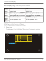
DIP switch (SW2) settings on the back panel are as follows:
Switch
Number
ON
OFF
Switch 1
Internal Clock
Network Clock
Switch 2
E1 External Loop-back Forbidden
E1 External Loop-back Allowed
Switch 3
Auto-resetting function Forbidden
Auto-resetting function Allowed
Switch 4
Auto-resetting Delay by 16 seconds
Auto-resetting Delay by 8 seconds
Switch 5
Manual Resetting Closed
Manual Resetting Opened
E1 Line Impedance : 75 W
E1 Line Impedance : 120 W
Switch 6
Switch 7
Switch 8
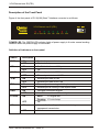
IN 75 W Represents the E1 unbalanced 75W input.
OUT 75 W Represents the E1 unbalanced 75W Output.
3
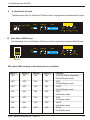
Bottom Panel
The bottom panel of the 10(100) Base-T Ethernet over E1 equipment is as follows.
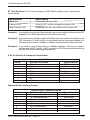
1
17
2-16, 18-32
Working Mode
SO
S16
S1-S15, S17-S31
OFF
OFF
OFF
OFF
ON
The occupied Time-slots at ON
OFF
The occupied Time-slots at ON
Unframed
Framed
Multiple Framed
ON
1
8
16 24 32
OFF
Orion Telecom Networks Inc. - 2009-10
9