1
USS
DDE
Server
for Microsoft Windows
and InTouch Applications
User Manual
Ver 1.x Rev 1.7
DR150 05
DR150 10
KLINKMANN AUTOMATION
P.O. Box 38
FIN-00371 Helsinki Finland
tel. int. + 358 9 5404940
fax int. + 358 9 5413541
www.klinkmann.com
Klinkmann Automation USS DDE Server
i
Table Of Contents
What is DDE?........................................................................................................................... 1
Accessing a Remote DDE Item from USS ............................................................................... 2
Installing the USS Server ......................................................................................................... 2
Wiring Diagram......................................................................................................................... 4
Configuring the USS Server ..................................................................................................... 5
DDE Server Settings Command ........................................................................................... 5
Com Port Settings Command ............................................................................................... 7
Saving USS Configuration File.............................................................................................. 8
Configuration File Location ................................................................................................... 8
Topic Definition Command.................................................................................................... 9
Using the USS Server with InTouch ....................................................................................... 11
Defining the Tag names...................................................................................................... 13
Converter "STATUS" Item .................................................................................................. 15
Item (Point) Naming................................................................................................................ 16
Parameter Items ................................................................................................................. 16
Process Data Words Items ................................................................................................. 17
Item (Point) Naming for 6RA22 .............................................................................................. 20
Parameter Items ................................................................................................................. 20
Telegram Data Words Items ............................................................................................... 21
Notes on Using Microsoft Excel.............................................................................................. 23
Reading Values into Excel Spreadsheets ........................................................................... 23
Writing Values to USS Points ............................................................................................. 23
Troubleshooting...................................................................................................................... 25
WIN.INI entries ................................................................................................................... 25
Troubleshooting menu ........................................................................................................ 26
USS DDE Server Ver 1.x User Manual Rev 1.7
150xxm17
Klinkmann Automation USS DDE Server
1
USS DDE Server
The USS DDE Server (hereafter referred to as the USS Server) is a Microsoft Windows 32bit application program that acts as a DDE (Dynamic Data Exchange) Server and allows other
Windows application programs an access to data from converter devices supporting USS
protocol (MICRO MASTER, 6SE21, 6RA24, 6RA22 etc.).
The Server is primarily intended for use with Wonderware InTouch, but it may be used by
any Microsoft Windows program that is capable of acting as a DDE Client.
What is DDE?
DDE is a complete communication protocol designed by Microsoft to allow applications in the
Windows environment to send/receive data and instructions to/from each other. It implements
a client-server relationship between two concurrently running applications. The server
application provides the data and accepts requests from any other application interested in its
data. Requesting applications are called clients. Some applications such as InTouch and
Excel can simultaneously be both a client and a server.
To obtain data from another application the client program opens a channel to the server
application by specifying three things: the server application name, the topic name and the
specific item name. For example, in the case of Excel, the application name is "Excel", the
topic name is the name of the specific spreadsheet that contains the data and the item name
is the specific cell on the spreadsheet. With InTouch the application name is "View", the topic
name is the word "Tagname" when reading/writing to an InTouch tag name and the item
name is a specific tag name in the InTouch Data Dictionary.
When a client application sets up a link to another DDE program, it requests the server
application to advise the client whenever a specific item's value changes. These data links
will remain active until either the client or server program terminates the link or the
conversation. They are a very efficient means of exchanging data because when the link has
been established no communication occurs until the specified data value changes. InTouch
uses DDE to communicate with DDE Servers and other DDE application programs.
USS DDE Server Ver 1.x User Manual Rev 1.7
150xxm17
Klinkmann Automation USS DDE Server
2
Accessing a Remote DDE Item from USS
The DDE protocol identifies an element of data by using a three-part address, including:
Application, Topic and Item.
Application refers to the name of the Windows program (server) that knows how to access
the data element. For the USS Server the application portion of the DDE address is USS.
Topic is an application-specific sub-group of data elements. The USS Server considers each
converter device to be a separate topic. The user creates a meaningful name for each device
and uses this name as the topic name for DDE references.
Item indicates a specific data element within the specified topic. For the USS Server, an item
is Converter’s internal Parameter or Process Data Word (or Bit of Process Data Word) of
communication message. (The item/point names are described in the Item (Point) Naming
and Item (Point) Naming for 6RA22 section.)
Note: In some cases, the term "point" is used interchangeably with the term "item".
Installing the USS Server
The USS DDE Server installation package can be supplied:
1. As a self-extracting archive 15010xxx.EXE if downloaded from Klinkmann’s web site
(the xxx is the current (latest) version of the Server).
2. From installation on CD.
3. On two or three distribution disks (floppies).
To install the USS DDE Server from the self-extracting archive, run the 15010xxx.EXE and
proceed as directed by the USS Server Setup program.
To install the USS DDE Server, on Windows (NT, 2000, XP or 95 (98)):
1. Insert the CD with Klinkmann Software into CD drive or insert the USS DDE Server
disk into a floppy drive A: or B:.
2. Select the Run command under the Start menu.
3. Run STARTUP.EXE if installing from CD or SETUP.EXE if installing from distribution
disks (floppies).
4. If installing from CD: select “Protocol Servers (DDE, SuiteLink, OPC)”, find “USS DDE
Server” and click on “Setup…”.
5. Proceed as directed by the USS Server Setup program.
When installation is finished, the subdirectory specified as a folder where to install the
USS DDE Server will contain the following files:
USS.EXE
The USS Server Program. This is a Microsoft Windows 32-bit
application program.
USS.HLP
The USS Server Help file.
USS DDE Server Ver 1.x User Manual Rev 1.7
150xxm17
Klinkmann Automation USS DDE Server
USS.CFG
An example configuration file.
LICENSE.TXT
Klinkmann Automation software license file.
WWCOMDLG.DLL
Dynamic Link Library necessary for USS Server.
3
To uninstall the USS Server, start Control Panel, select “Add/Remove Programs” and select
the “USS DDE Server” from the list of available software products. Click on “Add/Remove…”
and proceed as directed by the UnInstallShield program.
Note:
The HASP key is needed for full time running of USS Server. The HASP Driver setup is
performed during the Server setup. Without HASP Driver installed, the USS Server will run
only 1 hour (with all features enabled).
USS DDE Server Ver 1.x User Manual Rev 1.7
150xxm17
Klinkmann Automation USS DDE Server
4
Wiring Diagram
The run-time system consists of one or several converter devices (slaves) connected to the
host computer. The RS232 serial interface is used at computer side and RS232/RS485
converter must be used to communicate with converter devices. The RS232 to RS485
converter must ensure alternately (never at the same time) activation of the Receiver and the
Transmitter (the RTS signal is not generated by host computer and therefore if the RS232 to
RS485 converter uses RTS signal at RS232 side then RTS line must be connected to host
computer Transmitter line - see example wiring diagram).
The USS DDE Server is tested with the ENTRELEC model ILPH RS232/RS422-RS485 Serial
Link Interface configured as RS485 link on one pair and where the activation of the Receiver
and the Transmitter is performed depending on the status of the CTRL IN signal.
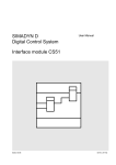
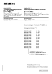
The following wiring diagram is useful if ENTRELEC converter is used to connect PC and a
slave (MicroMaster).
The RS232 between PC and ENTRELEC, RS485 between ENTRELEC and MicroMaster:
* Jumpers: Rt = 120 ohms, R = ON/OFF, E = ON/OFF.
USS DDE Server Ver 1.x User Manual Rev 1.7
150xxm17
Klinkmann Automation USS DDE Server
5
Configuring the USS Server
After the USS Server is initially installed, a little of configuration is required. Configuring the
Server automatically creates an USS.CFG file that holds all of the topic definitions entered,
as well as the communication port configurations. This file will be placed automatically in the
same directory in which USS.EXE is located unless the path where the configuration file will
be placed is specified via the /Configure/DDE Server Settings... command.
To perform the required configurations, start the USS program. If the Server starts up as an
icon then double-click on the icon to open the server's window. To access the commands
used for various configurations, open the /Configure menu:
DDE Server Settings Command
A number of parameters that control the internal operation of the Server can be set. In most
cases, the default settings for these parameters provide a good performance and do not
require changing. However, they can be changed to fine-tune the Server for a specific
environment.
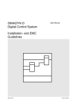
To change the Server's internal parameters, invoke the DDE Server Settings... command.
The "DDE Server Settings" dialog box will appear:
The following describes each field in this dialog box:
Protocol Timer Tick
This field is used to change the frequency at which the Server checks for work to do (at this
frequency one message is sent to the network and one reply from network is processed).
This should be approximately 2 to 4 times faster than rate desired to update data from the
network.
USS DDE Server Ver 1.x User Manual Rev 1.7
150xxm17
Klinkmann Automation USS DDE Server
6
NetDDE being used
Select this option if you are networking using NetDDE.
Configuration File Directory
This field is used to specify the path (disk drive and directory) in which USS will save its
current configuration file. The USS Server will use this path to load the configuration file the
next time it is started.
Note: Only the "path" may be modified with this field. The configuration file is always named
USS.CFG.
Note: There is no limit to the number of configuration files created, although each must be in
a separate directory. When using the USS Server with InTouch, it is good practice to place
the configuration file in the application directory.
Once all entries have been made, click on OK.
USS DDE Server Ver 1.x User Manual Rev 1.7
150xxm17
Klinkmann Automation USS DDE Server
7
Com Port Settings Command
This command is used to configure the communication port that will be used to communicate
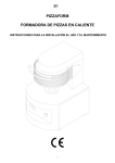
with converters. Invoke the Com Port Settings... command. The "Communication Port
Settings" dialog box will appear:
The following describes each field in this dialog box.
Com Port
Select the Com Port and examine the characteristics of the selected Port. To select a
necessary Com Port click on the combo box button and make your choice from the list box.
Reply Timeout
This field is used to enter the amount of time (in seconds) all converters using the selected
communication port will be given to reply to commands from the Server.
Note: The default value of 3 seconds should be sufficient for most configurations.
Baud Rate
The selected Baud Rate must match the converter setting.
Note: The default Baud Rate is 9600.
Other communication parameters are following: 8 Data Bits, 1 Stop Bit, Even Parity. These
parameters cannot be changed.
When all entries have been made, click on Done to process the configuration for the
communication port.
USS DDE Server Ver 1.x User Manual Rev 1.7
150xxm17
Klinkmann Automation USS DDE Server
8
Saving USS Configuration File
If the configuration file does not currently exist, or a new configuration path has been
specified, the Server will display the "Save Configuration" dialog box:
This dialog box displays the path where the Server is going to save the current configuration
file. The path may be changed if necessary. Also, the path can optionally be recorded in the
WIN.INI file by selecting the "Make this the default configuration file" option. Doing so it
will allow the USS Server to find the configuration file automatically each time it is started.
Configuration File Location
When the USS Server starts up, it first attempts to locate it’s configuration file by first
checking the WIN.INI file for a path that was previously specified. If the path is not present in
the WIN.INI file, the Server will assume that the current working directory is to be used.
To start the Server from an application directory configuration file other than the default
configuration file a special switch (/d:) is used. For example, invoke the File/Run command in
File Manager or Program Manager and enter the following:
USS /d:c:\directoryname
Note: There is no limit to the number of configuration files that may be created, although
each must be in a separate directory.
USS DDE Server Ver 1.x User Manual Rev 1.7
150xxm17
Klinkmann Automation USS DDE Server
9
Topic Definition Command
The user provides each connected converter with an arbitrary name that is used as the DDE
topic for all references to this converter.
The following steps are taken to define the Topic attached to the converter:
1.
Invoke the Topic Definition... command. The "Topic definition" dialog box will appear:
2.
To modify an existing topic, select the topic name and click on Modify. To define a new
topic, click on New. To remove an existing topic, click on Delete. The "USS Topic
Definition" dialog box will appear:
3.
Enter the Topic Name that corresponds to the DDE Topic Name (The DDE Topic Name
is entered in the "DDE Access Name Definition" dialog box described in the Using the
USS Server with InTouch section).
USS DDE Server Ver 1.x User Manual Rev 1.7
150xxm17
Klinkmann Automation USS DDE Server
10
4.
Enter the Station number for this converter device.
Note: Each converter must have a unique address from 0 to 30. Station number 255
can be used as a broadcast address. If some data is sent to this address then all
connected converters will receive these data. It is impossible to read data from topic
with Station number 255.
5.
Click on the Com Port button to associate a topic with the communication port.
Note: Additional topics may be associated with the same communication port later.
6.
Set the Max supported points for topic (converter). (Set the number of really used
(polled) items/points or little higher, not maximum allowed). Default value is 128.
7.
Set the Update Interval field to indicate the frequency the items/points on this topic will
be read (polled). Default value is 1000 milliseconds.
8.
Set the number of Parameter Data Words in the Master (PC) to Slave (converter)
message and in the response. Value less than 3 in this field means that there is no
parameter data in the message. To configure topic for messages containing 3
Parameter Data Words enter value 3 in this field. Default value is 3.
Note: Value set in this field must correspond to hardware settings. For example, on the
6RA24 the corresponding value is set in parameters P782, P792.
For converter type 6RA22 this option is not effective; in this case the Server operates
with 10-word telegram.
9.
Set the number of Process Data Words in the Master (PC) to Slave (converter)
message and in the response. Valid values in this field are from 0 to 15.
Note: Value set in this field must correspond to hardware settings. For example, on the
6RA24 parameters P781, P791 contain number of Process Data Words + the control
word. If value of parameters P781, P791 is 3 then value 2 must be entered in the
Process Data Words field. Default value is 2.
For converter type 6RA22 this option is not effective; in this case the Server operates
with 10-word telegram.
Note: Value 3 in the Parameter Data Words field and value 2 in the Process Data
Words field corresponds to simple protocol when each message contains 14 bytes.
Such values must be set for Siemens converters (MicroMaster, 6SE21).
10. Check the 6SE21 checkbox if converter type is 6SE21; check the 6RA22 checkbox if
converter type is 6RA22. In other cases do not check checkboxes.
11. When all entries have been made, click on OK to process the configuration for this topic.
USS DDE Server Ver 1.x User Manual Rev 1.7
150xxm17
Klinkmann Automation USS DDE Server
11
Using the USS Server with InTouch
To change process data words or to access items/points on converters from InTouch, the
following steps (all performed in WindowMaker) are required:
To define the DDE Access Names in WindowMaker for each converter invoke the
/Special/DDE Access Names... command. The "DDE Access Name Definition" dialog box will
appear.
Click on Add. The "Modify DDE Access Name" Dialog Box will appear:
Note: If Add is selected then this dialog box will be blank when it initially appears. Data has
been entered here to illustrate the entries that are made.
The following three fields are required entries when entering a DDE Access Name Definition:
DDE Access Name
Enter an arbitrary name that will be used by InTouch to refer to the topic (converter). It is
recommended that the name defined for the topic (converter) in USS also is to be used here.
DDE Application/Server Name
Enter the application name, USS, which the DDE Server used accessing the converter.
USS DDE Server Ver 1.x User Manual Rev 1.7
150xxm17
Klinkmann Automation USS DDE Server
12
DDE Topic Name
Enter the name defined for the topic in USS to identify the converter the USS Server will be
accessing.
Note: This will usually be the same as the "DDE Access Name", although, if desired, they
may be different. However, it must be the same name used when the topics were configured
in section Configuring the USS Server.
Request Initial Data
This option may be selected if the Server is other than a Wonderware DDE Server and the
Server does not return data values immediately when a window is displayed. This option is
not applicable to the USS DDE Server.
Wait for Change
This option should be selected for USS DDE Server.
Advise all Items
This option may be selected if the Server is to poll for all data whether or not it is in visible
windows, alarmed, logged or trended. Use of the option is not recommended.
Advise only active Items
Selecting this option will cause the USS Server to poll only points in visible windows and
points that are alarmed, logged or trended.
USS DDE Server Ver 1.x User Manual Rev 1.7
150xxm17
Klinkmann Automation USS DDE Server
13
Defining the Tag names
To define the Tag names associated with the new "DDE Access Name", invoke the
/Special/Tagname Dictionary... command (in WindowMaker). The "Dictionary - Tagname
Definition" dialog box will appear:
Click on New and enter the Tag Name. (The tag name defined here is the name InTouch will
use. The USS Server does not see this name.)
Select the tag type by clicking on the Type button. The "Choose tag type" dialog box will
appear:
In order to access USS items, the type must be DDE Discrete, DDE Integer or DDE Real.
Select the DDE type.
The "Details" dialog box for the tag name will appear:
Select the USS topic (converter) by clicking on the DDE Access Name... button. The "DDE
Access Name Definition" dialog box will appear:
USS DDE Server Ver 1.x User Manual Rev 1.7
150xxm17
Klinkmann Automation USS DDE Server
14
Select the appropriate topic name and click on Done. (If the DDE Access Name has not been
defined as previously described, click on Add and define the DDE topic now.)
The "Details" dialog box will appear displaying the selected DDE Access Name:
For integers and reals fill in the Min EU, Max EU, Min Raw and Max Raw fields. These fields
control the range of values that will be accepted from the server and how the values are
scaled. If no scaling is desired, Min EU should be equal to Min Raw and Max EU equal to
Max Raw.
Enter the USS item/point name to be associated with this tag name in the Item field in the
"Details" box:
USS DDE Server Ver 1.x User Manual Rev 1.7
150xxm17
Klinkmann Automation USS DDE Server
15
(Refer to the Item (Point) Naming and Item (Point) Naming for 6RA22 section below for
complete details.)
Where applicable, the Use Tag name as Item Name option may be selected to automatically
enter the tag name in this field. Note: The tag name can only be used if it follows the
conventions listed in the Item (Point) Naming and Item (Point) Naming for 6RA22 section.
Once all entries have been made, click on the Save button (in the top dialog box) to accept
the new tag name. To define additional Tag names click on the New button. To return to the
WindowMaker main screen, select Done.
Converter "STATUS" Item
For each topic, there is a built-in discrete item that indicates the state of communication with
the Converter. The discrete item (Status) is set to 0 when communication with the Converter
fails and set to 1 when communication is successful.
From InTouch the state of communications with the Converter may be read by defining a
DDE Discrete tagname and associating it with the topic configured for the Converter and
using Status as the Item name.
From Excel, the status of the communications may be read by entering the following formula
in a cell:
=USS|topic!STATUS
USS DDE Server Ver 1.x User Manual Rev 1.7
150xxm17
Klinkmann Automation USS DDE Server
16
Item (Point) Naming
This chapter deals with Item (Point) naming for communication with all types of converters
except 6RA22.
The USS Server can access up to 1023 Parameter Words from the Converter internal
memory. The Server supports additional items representing Process Data Words and bits of
these words, which allows user to check the contents of messages and to control the data
exchanging between Server and Converter, as well as to control the Converter performance.
Parameter Items
The Items representing Parameter Words are used to access the Converter internal
parameters. Item/point names representing Parameter Words generally may be described as:
PnImE
Where P -
prefix which identifies the type of Item. The following characters can be used:
D(d) - Discrete Item; I(i) - signed Integer Item; U(u) - unsigned Integer Item;
F(f) - Float Item (Item with value adjusted in 0.1 steps); R(r) - Float Item (Item
with value adjusted in 0.01 steps).
n - specifies the Parameter number. Do not use Parameter numbers unsupported
on your Converter.
I - optionally used suffix (I or i), indicating that Item value is accessible by Indexed
parameter value request or Indexed parameter value change message.
m - Index for Parameter Number. Value m will be set in the PKW Word 2 of
message. Index m is used only with suffix I (i).
E - optionally used suffix (E or e), indicating that Item value must be changed both
in RAM and EEPROM.
If two suffixes "E" ("e") and "I" ("i") are used simultaneously then Indexed
parameter value must be changed both in RAM and EEPROM.
Set the item type according to your hardware (see Converter manual). For example, the
MicroMaster parameter P015 has only two possible values (0 and 1) and item type can be
Integer or Discrete. Valid item names are: D15, I15 and U15.
The MicroMaster parameter P016 has three possible values. In this case item type must be
Integer and valid item names are: I16 and U16.
The MicroMaster parameter P012 values may be set between 0.0 and 650.0 Hertz, i.e.
parameter value is adjusted in 0.1 steps. In this case the data format is scaled to 0.1 and item
name F12 is useful. If poke F12 then the Server takes the Float value of F12, converts it to 16
bit Short Integer scaled in 0.1 steps and puts it into VAL field of send telegram. For example,
if poked F12 value is 30.1 then the VAL field in telegram will contain 301.
So, to poke value 30.1 into parameter P012 the following Item names with corresponding
values can be used:
Item F12 with value 30.1,
Item R12 with value 3.01,
Item I12 with value 301,
USS DDE Server Ver 1.x User Manual Rev 1.7
150xxm17
Klinkmann Automation USS DDE Server
17
Item U12 with value 301. In all these cases the same telegram will be transferred to the drive.
Items representing Parameter Words (PnImE) usually are Read/Write type. The server does
not check whether Item value can be changed in the Converter. See Converter manual
before try to write new value into Converter memory.
Process Data Words Items
The USS Server supports a list of Items that allow to control the contents of messages sent
to the controlled Converter and to check the response received from Converter. Item names
mainly depend on Siemens USS protocol (for MicroMaster, 6SE21) message fields naming
as well as on this protocol extension for 6RA24 converters.
The number of Process Data Words in message depends on Converter and protocol type
and can be configured during topic configuration. The default values (after server start-up) for
items representing Process Data Words (and Bits of Process Data Words) are zeroes (0).
When the Server is restarted the Process Data Words have default values (zeroes) again.
To perform the Converter control by items representing Process Data Words or Bits of
Process Data Words the corresponding Items must be activated in user application and
necessary values must be assigned to them. For example, to allow the MicroMaster to run,
the user application must set an Item STW value to 3199. If any Process Data Words Item
value is changed the Server sends message with changed Process Data Word value. All next
messages sent by the Server will contain the changed Process Data Word value until the
user application changes the Process Data Word value again. To recognise the right
sequence for changing of Process Data Word values see your hardware manual.
The table below lists the Item/point names representing Process Data Words and bits of
these words.
Item name
STW
STW.n
HSW
UHSW
ZSW
ZSW.n
HIW
UHIW
FHIW
PKE_CONTROL
ERROR_COD
PZDSn
UPZDSn
PZDRn
UPZDRn
Type
Word
Bit
Word
Word
Word
Bit
Word
Word
Word
Word
Word
Word
Word
Word
Word
DDE Tag
Type
Integer
Discrete
Signed Integer
Integer
Integer
Discrete
Signed Integer
Integer
Real
Integer
Integer
Signed Integer
Integer
Signed Integer
Integer
USS DDE Server Ver 1.x User Manual Rev 1.7
Value Range
0...65535
0,1
-16384...16384
0...65535
0...8191
0,1
-16384...16384
0...65535
0...65535
0...15
0...255
-32768...32767
0...65535
-32768...32767
0...65535
n
Range
Default
Value
0*
0 to 15
0 to 15
0
0
0
0
0
0
0
2 to 15
2 to 15
2 to 15
2 to 15
0
0
0
0
150xxm17
Klinkmann Automation USS DDE Server
18
(*) For Server versions from v1.0 to v1.3 the default value of STW is 3191. In Server version
1.4 and later the default value is 0 (zero).
Notes:
1. The item STW represents first Process Data Word in the send message. Items
STW.0...STW.15 represent bits of the first Process Data Word (STW). For 6RA24 the item
STW is used instead of PZD0 Word. Each bit in STW Word has a predefined meaning, which
depends on Converter and protocol type.
2. The item HSW is second Process Data Word in the send message and represents the
frequency demand. For 6RA24 the item HSW is used instead of PZD1 Word. For
MicroMaster the values 0...32767 represent 0...200%, values 32768...65535 represent
reversed 0...200%. For 6SE21 the negative demand is not supported and frequency demand
above 100% is clipped to 100%. If only positive frequency demand values are supported then
the item UHSW can be used. For 6RA24 the frequency demand to the converter is scaled as
follows: the value 16384 represents 100%, value -16384 represents -100% (i.e. reverse),
therefore an Item HSW must be used.
3. The item ZSW represents first Process Data Word in the response message. Items
ZSW.0...ZSW.15 represent bits of the first Process Data Word ZSW. For 6RA24 the item
ZSW is used instead of PZD0 Word.
4. The item HIW is the second Process Data Word in the response message and represents
the output frequency of the Converter. For 6RA24 the item HIW is used instead of PZD1
Word. The item value is formatted in same way as for the HSW field. For MicroMaster,
6SE21 and other converters supporting only positive HIW values the item UHIW can be used.
The 6SE21 returns the current value scaled to 0.1 Amps in HIW field if the STW field bit 15
was set to 1. In this case the item FHIW must be used.
5. The item PKE_CONTROL value is extracted from the response message’s PKE word
(control bits with addresses 12, 13, 14 and 15). The possible values are: 0 - no action, 1 parameter value is in the response VAL field, 4 - indexed parameter value transferred, 7 error in the received command, 8 - the Converter is in Local Control (parameter change
request not possible).
6. If the PKE_CONTROL value is 7 then the item ERROR_COD value contains the error
code. The possible error codes are: 0 - Illegal Parameter Number, 1 - Read Only Parameter
(not supported on 6SE21), 2 - the parameter value requested in PKW word 3 is beyond the
minimum or maximum limits of acceptable values, 3 - the index sent in PKW word 2 is
undefined, 11 - the request code sent in PKW word 1 is not implemented, 101 - the request
code function sent in PKW word 1 is not implemented, 102 - the parameter is an indexed
parameter. If no errors, ERROR_COD value is 255.
7. The items PZDS2...PZDS15 represent Process Data Words in the send message in case
of 6RA24 converters. The items STW and HSW are used instead of PZDS0 and PZDS1. The
values of items PZDS2... PZDS15 are interpreted as signed Integers. If values must be
interpreted as unsigned integers the items UPZDS2...UPZDS15 can be used.
USS DDE Server Ver 1.x User Manual Rev 1.7
150xxm17
Klinkmann Automation USS DDE Server
19
8. The items PZDR2...PZDR15 represent Process Data Words in the response message in
case of 6RA24 converters. The items ZSW and HIW are used instead of PZDR0 and PZDR1.
The values of items PZDR2... PZDR15 are interpreted as signed Integers. If values must be
interpreted as unsigned integers the items UPZDR2...UPZDR15 can be used.
Important: In USS DDE Server version 1.4 and later the default values of all Process Data
Words after Server startup are zeroes (0).
The Server does not perform any communication while Process Data Word STW is default
(zero). It allows the user application to set the necessary values into all Process Data Words
before sending the first request to the equipment. Otherwise the Server can send to drive a
command with incorrect Process Data Words and so interrupt good performance of
equipment.
While STW is zero the Server does not create any write command, it is, the Server does not
react to pokes of Parameter data words at all.
To make the Server to communicate the following should be done:
- Poke correct values into Process Data Words (except STW). For example, in case of
MicroMaster drive, firstly poke value of HSW (e.g. 16384),
- poke into STW correct non-zero value, for example, value 3199 (in case of MicroMaster).
For each Topic there is also a built-in discrete item (STATUS) that indicates the state of
communication with the Converter. This discrete item is set to 0 when communication with
the Converter fails and set to 1 when communication is successful.
The items STW, STW.n, HSW, UHSW, UPZDSn and PZDSn are Write Only.
The items ZSW, ZSW.n, HIW, UHIW, FHIW, PKE_CONTROL, ERROR_COD, PZDRn and
UPZDRn are Read Only.
Item/Point Naming Examples
The following examples show the valid item names:
I33
converter parameter number 33, interpreted as Integer.
U12E
converter parameter number 12, change in RAM and EEPROM,
interpreted as unsigned Integer.
f51i2E
converter parameter number 51, indexed parameter change in
RAM and EEPROM, index value 2, interpreted as Float.
i78i1
converter parameter 78, indexed parameter, index value 2,
interpreted as Integer.
PZDS3
the third PZD Control Word for 6RA24 in send message.
STW.4
Bit number 4 in the STW Control Word.
USS DDE Server Ver 1.x User Manual Rev 1.7
150xxm17
Klinkmann Automation USS DDE Server
20
Item (Point) Naming for 6RA22
This chapter deals with Item (Point) naming for communication with 6RA22 type converter.
The USS Server can access up to 390 Parameter Words from the 6RA22 Converter internal
memory. The Server supports additional items representing Telegram Data Words, which
allows user to check the contents of messages and to control the data exchanging between
Server and Converter, as well as to control the Converter performance.
Parameter Items
The Items representing Parameter Words are used to access the Converter internal
parameters. Item/point names representing Parameters generally may be described as:
PNn
Where P - prefix that identifies the type of Item. The following characters can be used:
B(b) - Discrete Item; I(i) - signed Integer Item; U(u) - unsigned Integer Item (value
0...65535); F(f) - Float Item (Item with value adjusted in 0.1 steps); R(r) - Float Item
(Item with value adjusted in 0.01 steps).
N - prefix that identifies the Parameter name. The following characters can be
used:
P(p) specifies the Parameters P00 to P177; n values 0...177 correspond to
parameter numbers 00 to 177.
d(D) specifies the Parameters d00 to d30; n values 0...30 correspond to
parameter numbers 200 to 230.
H(h) specifies the Parameters H00 to H89; n values 0...89 correspond to
parameter numbers 300 to 389.
n - specifies the Parameter number. Do not use Parameter numbers unsupported
on your Converter.
If the Server does not accept Item name without prefix that identifies the type of Item (is it
Discrete or Integer or other type), then the error message in WWLogger file “Invalid item/point
name: …” appears. In this case Item name should be modified so that type of Item is set in
Item name by prefix. Define the item type according to your hardware (see Converter
manual). For example, the parameter described in Converter manual as E73 has possible
values 0...15 and item type can be integer or unsigned integer. Valid item names are: IP173,
and UP173.
Float items are useful if parameter value is adjusted in 0.1 or 0.01 steps. In this case item
names with prefix F(f) or R(r) are useful. If poke some value into such Float item then the
Server takes the Float value, converts it to 16 bit Short Integer scaled in 0.1 or 0.01 steps and
puts it into value field of send telegram. For example, if poked value of item with prefix F(f) is
30.1 then the value field in telegram will contain 301.
So, to poke value 30.1 the following Item names with corresponding values can be used:
Item name with prefix F(f) with value 30.1,
Item name with prefix R(r) with value 3.01,
Item name with prefix I(i) with value 301,
Item name with prefix U(u) with value 301. In all these cases the same telegram will be
transferred to the drive.
USS DDE Server Ver 1.x User Manual Rev 1.7
150xxm17
Klinkmann Automation USS DDE Server
21
Items representing Parameter Words (Pn) usually are Read/Write type. The server does not
check whether Item value can be changed in the Converter. See Converter manual before try
to write new value into Converter memory.
Additional DDE Discrete Items P1022 and P1023 are supported by the USS DDE Server in
broadcast mode (for Topic number 255).
When value of P1022 is changed by application from 0 to 1, the Server sends a broadcast
message where only the control commands of word E3 are processed by the converter.
When value of P1023 is changed by application from 0 to 1, the Server sends a broadcast
message where only the control commands of word E3 and the setpoint of word E2 are
processed by the converter.
Telegram Data Words Items
A 10-word telegram is used for communication with 6RA22 Converter. The USS Server
supports a list of Items that allows to control the contents of messages sent to the 6RA22
Converter and to check the response received from Converter.
The default values for items representing Telegram Data Words in Host to Drive telegram are
zeroes (0). To change the default values - add the following WIN.INI file Items 6RA22_E2,
6RA22_E3, 6RA22_E5, 6RA22_E6, 6RA22_E7, 6RA22_E8, 6RA22_E9 and 6RA22_E10
with necessary default values into WIN.INI file (see chapter Troubleshooting). The default
values are set into the send messages after the Server startup. To change contents of
message during Server performance an application must assign correct values to E2, E3, E5,
E6, E7, E8, E9, E10 Items.
Important:
Set correct values to 6RA22_E2, 6RA22_E3, 6RA22_E5, 6RA22_E6, 6RA22_E7,
6RA22_E8, 6RA22_E9 and 6RA22_E10 in WIN.INI file before Server start-up. Otherwise the
Server can send to drive a command with incorrect Telegram Data Words and so interrupt
good performance of equipment.
If any Telegram Data Words value is changed the Server sends message with changed
Telegram Data Word value. All next messages sent by the Server will contain the changed
Telegram Data Word value until the user application changes the Telegram Data Word value
again.
The table below lists the Item/point names representing Telegram Data Words.
Item name
En
Uen
Sn
Usn
Type
DDE Tag Type
Value Range*
n Range
Word
Word
Word
Word
Signed Integer
Unsigned Integer
Signed Integer
Unsigned Integer
-32768...32767
0...65535
-32768...32767
0...65535
2...10
2...10
1...10
1...10
Default
Value
0
0
0
0
(*) Values of Speed Reference Items are limited to -16384 ... 16384 or 0 ... 16384.
USS DDE Server Ver 1.x User Manual Rev 1.7
150xxm17
Klinkmann Automation USS DDE Server
22
Notes:
1. The items En represent Telegram Data Words in the send message. Value of En is
interpreted by the Server as signed integer. If values must be interpreted as unsigned
integers the items UEn can be used.
Value of E1 is generated by the Server and is not accessible by application.
Value of word E4 (UE4) is set by the Server, when operates not in a broadcast mode: for
read messages - 0, for write messages - value to be placed in the parameter identified in
word E1. When in a broadcast mode this word value is set by application and contains a bit
mask to allow selective operation of the control bits in word E3.
All other Telegram Data Word values can be changed by an application (Write only type).
2. The items Sn represent Telegram Data Words in the response message. Value of Sn is
interpreted by the Server as signed integer. If values must be interpreted as unsigned
integers the items USn can be used.
All Item (S1...S10) values are accessible by application, but can not be changed by
application (Read only type). Parameter value (S4) is extracted by the Server and given to
application as correspondent parameter Pn value.
For each Topic there is also a built-in discrete item (STATUS) that indicates the state of
communication with the Converter. This discrete item is set to 0 when communication with
the Converter fails and set to 1 when communication is successful.
Item/Point Naming Examples
The following examples show the valid item names:
id9
converter parameter number 209, interpreted as signed
Integer.
Ud10
converter parameter number 210, interpreted as unsigned
Integer.
E3
Telegram Data Word number 3 in send message interpreted as
signed Integer.
S10
Telegram Data Word number 10 in response message
interpreted as signed Integer.
US3
Telegram Data Word number 3 in response message interpreted
as unsigned Integer.
USS DDE Server Ver 1.x User Manual Rev 1.7
150xxm17
Klinkmann Automation USS DDE Server
23
Notes on Using Microsoft Excel
Data from topics may be accessed from Excel spreadsheets. To do so, enter a formula like
the following into a cell on the spreadsheet.
=USS|topic!item
Sometimes, Excel requires the topic and/or item/points to be surrounded by apostrophes.
In the formula, topic must be replaced with one of the valid topic names defined during the
Server configuration process. Replace item with one of the valid item/point names described
in the Item (Point) Naming or Item (Point) Naming for 6RA22 section.
Reading Values into Excel Spreadsheets
Values can be read directly into Excel spreadsheets by entering a DDE formatted formula into
a cell, as shown in the following examples:
=USS|plc01!U33i4E
=USS|pc!PZDR6
=USS|converter1!HIW
The status item can be read by entering the following formula in a cell:
=USS|topic!STATUS
Writing Values to USS Points
Values may be written to USS Server from Microsoft Excel by creating an Excel macro that
uses the POKE command. The proper command is entered in Excel as follows:
channel=INITIATE("USS","topicname")
=POKE(channel,"itemname", Data_Reference)
=TERMINATE (channel)
=RETURN()
The following describes each of the above POKE macro statements:
channel=INITIATE("USS","topicname")
Opens a channel to a specific topic name (defined in the Server) in an application with name
USS (the executable name less the .EXE) and assigns the number of that opened channel to
channel.
Note: By using the channel=INITIATE statement the word channel must be used in
the =POKE statement instead of the actual cell reference. The "applicationname"
and "topicname" portions of the formula must be enclosed in quotation marks.
USS DDE Server Ver 1.x User Manual Rev 1.7
150xxm17
Klinkmann Automation USS DDE Server
24
=POKE(channel,"itemname", Data_Reference)
POKEs the value contained in the Data_Reference to the specified item name (actual
parameter on the drive) via the channel number returned by the previously executed
INITIATE function. Data_Reference is the row/column ID of the cell containing the data
value. For "itemname", use some of the valid item names described in the Item (Point)
Naming section.
=TERMINATE(channel)
Closes the channel at the end of the macro. Some applications have a limited number of
channels. Therefore they should be closed when finished. Channel is the channel number
returned by the previously executed INITIATE function.
=RETURN()
Marks the end of the macro.
The following is an example of Excel macro used to poke value from cell B2 to topic unit1
item U33i4E:
PokeMacro -Ctrl a
=INITIATE("USS","unit1")
=POKE(A2,"U33i4E",B2)
=ON.TIME(NOW()+0.01,"TerminateDDEChannel")
=RETURN()
TerminateDDEChannel
=TERMINATE(A2)
=RETURN()
Note: Refer to the Microsoft Excel manual for complete details on entering Remote
Reference formulas for cells.
USS DDE Server Ver 1.x User Manual Rev 1.7
150xxm17
Klinkmann Automation USS DDE Server
25
Troubleshooting
WIN.INI entries
The first time you run the USS Server configuration, most of the items in the following list will
automatically appear in the WIN.INI file. It is usually in the C:\WINDOWS directory. It is an
ASCII file and can be altered manually if you wish with any text editor, e.g. MS Windows
Notepad (do not use a program that formats text, such as MS Word or Write unless the file is
saved as DOS text). The following is a typical entry for the USS Server:
[USS]
ProtocolTimer=50
RequestTimer=1000
ValidDataTimeout=60000
DDEBlockSize=4096
WriteRetryIndefinitely=0
ConfigurationFile=C:\USS\
WinIconic=0
WinFullScreen=0
WinTop=112
WinLeft=0
WinWidth=200
WinHeight=168
ShowSend=0
ShowReceive=0
ShowErrors=1
For 6RA22 device the following Items can be added to change the default values for
communication telegram words E2, E3, E5, E6, E7, E8, E9 and E10:
6RA22_E2=0
6RA22_E3=0
6RA22_E5=0
6RA22_E6=0
6RA22_E7=0
6RA22_E8=0
6RA22_E9=0
6RA22_E10=0
Set values you need instead of zeroes.
USS DDE Server Ver 1.x User Manual Rev 1.7
150xxm17
Klinkmann Automation USS DDE Server
26
Troubleshooting menu
The following debugging choices are appended to the Server’s System Menu (the menu that
appears when you click the “-” box in the upper left hand corner of the Server window):
Suspend Protocol / Resume Protocol - these choices permit you to turn protocol
processing on and off, what allows you to suspend access to the Converter(s).
Show Send
Show Receive
Show Errors
Dump
- if checked then all outgoing data is displayed in hexadecimal format.
- if checked then all incoming data is displayed in hexadecimal format.
- if checked then all information about errors is displayed.
- displays all information about opened ports, active topics and data items.
All debug is displayed via the Wonderware Logger, which must be active for these commands
to work.
Warning: if you check Show Send and/or Show Receive then the debug output grows very
fast.
USS DDE Server Ver 1.x User Manual Rev 1.7
150xxm17
Klinkmann Automation USS DDE Server
27
KLINKMANN AUTOMATION
USS DDE Server
Revision History
Aug 95
Jan 96
Jan 96
Oct 96
Rev 1.0
Rev 1.1
Rev 1.2
Rev 1.3
Sep 97
Jan 2001
Mar 2001
Mar 2002
Rev 1.4
Rev 1.5
Rev 1.6
Rev 1.7
First Release
Changed Default Values of Process Data Words
Added Access to 6RA22 Converter
Modification of manual contents
Chapters:
Files on the USS Distribution Disks
Installing the USS DDE Server
Manual file name changed. Minor changes.
Corrected Item/Point naming for 6RA22 Converter.
Corrected Item/Point naming.
Installation from CD information added.
USS DDE Server Ver 1.x User Manual Rev 1.7
150xxm17