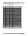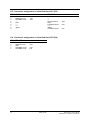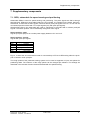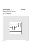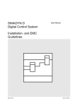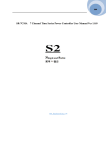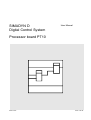
1
SIMADYN D
Digital Control System
User Manual
Processor board PT10
Edition 05.95
DK-Nr. 224162
User Manual, Processor board PT10
Edition
Edition status
1
Processor board PT10
11.94
2
Processor board PT10
05.95
Copying of this document and giving it to others and the use or
communication of the contents thereof is forbidden without express
authority. Offenders are liable to the payment of damages. All rights
are reserved in the event of the grant of a patent or the registration of
a utility model or design.
We have checked the contents of this Manual to ensure that they
coincide with the described hardware and software. However,
deviations cannot be completely ruled-out, so we cannot guarantee
complete conformance. However, the information in this document is
regularly checked and the necessary corrections included in
subsequent editions. We are thankful for any recommendations or
suggestions.
Contents
Contents
Warning information................................ ................................ ................................ .................... 1
1. Ordering information ................................ ................................ ................................ ...............3
2. Function description................................ ................................ ................................ ................3
3. Board design................................ ................................ ................................ ........................... 4
4. Application and installation information ................................ ................................ ...................5
4.1. Jumper setting ................................ ................................ ................................ .........5
5. Technical data................................ ................................ ................................ ......................... 6
5.1. GENERAL INFORMATION................................ ................................ ...................... 6
5.2. BINARY INPUTS ................................ ................................ ................................ .....6
5.3. BINARY OUTPUTS ................................ ................................ ................................ .6
5.4. ANALOG OUTPUTS................................ ................................ ................................ 7
5.5. ANALOG INPUTS................................ ................................ ................................ ....7
5.6. SPEED SENSING ................................ ................................ ................................ ...7
6. Connector assignment of PT10................................ ................................ ............................... 8
6.1. Connector X5: Analog inputs/outputs and speed sensing................................ ..........8
6.2. Connector X6: Assignment of the binary inputs and outputs................................ .....9
6.3. Connector assignment of serial interface X01 (X3)................................ ...................10
6.4. Connector assignment of serial interface X02 (X4)................................ ...................10
7. Supplementary components................................ ................................ ................................ ....11
7.1. SE59, submodule for speed sensing and positioning................................ ................11
7.2. Interaction between rough- (GI) and fine pulses (FI)................................ .................12
7.2.1. Type 0 ................................ ................................ ................................ .......12
7.2.2. Type 1 ................................ ................................ ................................ .......12
7.2.3. Type 2 ................................ ................................ ................................ .......12
7.2.4. Control register................................ ................................ .......................... 13
7.3. SE58, terminal block for connecting plant signals ................................ .................... 13
7.3.1.Terminal assignment of terminal block SE58, pin row X5............................ 14
7.3.2. Terminal assignment of terminal block SE58, pin row X6........................... 15
8. Others................................ ................................ ................................ ................................ .....16
8.1. Layout diagram PT10................................ ................................ ............................... 16
8.2. Layout diagram MS47................................ ................................ .............................. 17
8.3. Layout diagram SE59 ................................ ................................ .............................. 17
8.4. Layout diagram SE58 ................................ ................................ .............................. 17
8.5. Diagrams ................................ ................................ ................................ .................18
8.6. Dimension drawing ................................ ................................ ................................ ..19
9. ECB instructions................................ ................................ ................................ ...................... 20
Siemens AG Dk-Nr. 224162
SIMADYN D Hardware User Manual
Edition 05.95
Warning information
Edition 05.95
Siemens AG Dk-Nr. 224162
SIMADYN D Hardware User Manual
Warning information
NOTE!
The information in this Manual does not purport to cover all details or variations in equipment, nor to provide
for every possible contingency to be met in connection with installation, operation or maintenance.
Should further information be desired or should particular problems arise which are not covered sufficiently for
the purchaser’s purposes, please contact your local Siemens office.
Further, the contents of this Manual shall not become a part of or modify any prior or existing agreement,
committment or relationship. The sales contract contains the entire obligation of Siemens. The warranty
contained in the contract between the parties is the sole warranty of Siemens. Any statements contained
herein do not create new warranties nor modify the existing warranty.
Warning information
WARNING!
Electrical equipment has components which are at dangerous voltage levels.
If these instructions are not strictly adhered to, severe bodily injury and material
damage can result.
Only appropriately qualified personnel may work on this equipment or in its
vicinity.
This personnel must be completely knowledgeable about all the warnings and
service measures according to this User Manual.
The successful and safe operation of this equipment is dependent on proper
handling, installation, operation and maintenance.
Siemens AG Dk-Nr. 224162
SIMADYN D Hardware User Manual
Edition 05.95
1
Warning information
Definitions
*
QUALIFIED PERSONNEL
*
DANGER
*
WARNING
*
CAUTION
*
NOTE
For the purpose of this User Manual and product labels, a „Qualified person“ is someone who is familiar with the
installation, mounting, start-up and operation of the equipment and the hazards involved. He or she must have
the following qualifications:
1. Trained and authorized to energize, de-energize, clear, ground and tag circuits and equipment in accordance
with established safety procedures.
2. Trained in the proper care and use of protective equipment in accordance with established safety
procedures.
3. Trained in rendering first aid.
For the purpose of this User Manual and product labels, „Danger“ indicates death, severe personal injury and/or
substantial property damage will result if proper precautions are not taken.
For the purpose of this User Manual and product labels, „Warning“ indicates death, severe personal injury or
property damage can result if proper precautions are not taken.
For the purpose of this User Manual and product labels, „Caution“ indicates that minor personal injury or
material damage can result if proper precautions are not taken.
For the purpose of this User Manual, „Note“ indicates information about the product or the respective part of the
User Manual which is essential to highlight.
CAUTION!
This board contains components which can be destroyed by electrostatic
discharge. Prior to touching any electronics board, your body must be electrically
discharged. This can be simply done by touching a conductive, grounded object
immediately beforehand (e.g. bare metal cabinet components, socket protective
conductor contact).
WARNING!
Hazardous voltages are present in this electrical equipment during operation.
Non-observance of the safety instructions can result in severe personal injury or
property damage.
It is especially important that the warning information in all of the relevant
Operating Instructions are strictly observed.
2
Edition 05.95
Siemens AG Dk-Nr. 224162
SIMADYN D Hardware User Manual
Ordering information
1. Ordering information
Type:
Order No. (MLFB) Designation
Internal item
number
PT10:
SE58:
SC58:
SC60:
6DD 3440-0AB0
6DD 3460-0AB0
6DD 3461-0AB0
6DD 3461-0AE0
Processor board PT10
Terminal block for PT10
40-core screened round cable for PT10
34-core screened round cable for PT10
465 440 9001.00
465 460 9001.00
465 461 9001.00
465 461 9004.00
PT10P1: 6DD 3440-0AB3
Package consisting of PT10, SE58, SC58,
SC60
465 440 9001.30
MS47:
SE59:
6DD 3440-0AB2
6DD 3460-0AC0
Memory submodule for PT10
Incremental encoder module for PT10
465 440 9001.20
456 440 9002.00
PP1I:
PP1X:
UP3:
6DD 1670-0AE0
6DD 1670-0AD0
6DD 3462-0AB0
Parallel prommer (desktop unit)
Parallel prommer (chassis unit)
Programming adapter for MS47
465 670 9004.00
465 670 9005.00
465 462 9001.00
SW20:
6DD 3470-0AC0
SW20:
SW20:
SW30:
SW30:
SW30:
6DD 3470-0AC2
6DD 3481-0BA0
6DD 3470-0AD0
6DD 3470-0AD2
6DD 3481-0CA0
Angular synchronism on memory
submodule MS47
"
on floppy disk
Description, angular synchronism
Axial winder on memory submodule MS47
"
on floppy disk
Description, axial winder
SRT:
6DD 1682-0CF0
Technology box SRT
465 682 9025.00
2. Function description
The PT10 processor board is used in 6SE12/13, 6RA24 converters and in the SRT technology box. It
is used to process technological open- and closed-loop control and arithmetic functions and occupies
one slot.
The board contains a 16-bit microprocessor 80C186-20 MHz with the associated peripherals. The
input and output of binary and analog signals and the incremental encoder signals is realized via
terminal block SE58. The connection between PT10 and SE58 is realized through SC58 and SC60
round cables.
The SE59 option board can be used to sense incremental encoder signals. It is plugged onto the
processor board.
The plug-in MS47 program memory modules are used as data medium for the board user program as
well as for the system firmware (operating system, monitoring program, function block code...). The
user program runs on the processor under the SIMADYN D real-time operating system. This
guarantees, depending on the configuring using interrupts, controlled cycle times of ≥ 1 ms. An LED
(D5) indicates that the board is operating cyclically, error-free.
The boards are programmed using the UP3 programming adapter on PG710, PG730, PG750
programming units or with the parallel programming units PP1I and PP1X. The programming units
can be connected to the parallel interface of standard PCs.
The SW 20 software package (angular synchronism) and SW30 (axial winder) are available for
standard applications. The standard software packages are designed, both for use with the CS51
communications board and without it. It can also be used in the technology box SRT without a basic
converter (6SE12/13, 6RA24).
Siemens AG Dk-Nr. 224162
SIMADYN D Hardware User Manual
Edition 05.95
3
Board design
Serial interfaces X01 and X02 (connectors X3/X4) serve as communications- and service interfaces.
The HEX monitor can be activated using jumper J1 for diagnostics and monitoring purposes. When
the jumper is inserted, the hex monitor is enabled at restart, or when an error message is present,
outputs the associated information.
Three watchdogs are provided for each processor board to monitor the functioning of the hardware
and software.
The hardware monitoring functions check:
- ready signal delay for system bus accesses.
- double address coding errors
- whether addresses are accessed, which are unused
- system bus fault messages
The software monitoring functions check:
- whether the process still runs cyclically.
- whether the interrupt control of the serial interface,
timer and inputs operate error-free.
If the monitoring function identifies a fault/error, a "non-maskable interrupt" (NMI) is generated and
the processor attempts to remove the cause of the fault to re-establish cyclic operation. If the cause
of the fault/error is the processor itself, the board is de-activated.
3. Board design
- Dual port RAM 2 K * 8 to couple with the basic converter unit
- Connection for coupling to the dual port RAM of the interface board
- Version for operation with natural air cooling
- CPU 80C186 - 20 MHz
- RAM 128 kbyte
- Use of the MS47 SIMADYN D memory module
MS47 EPROM 256 K * 16 EEPROM 2 K * 8
- 7 differential analog inputs
inputs, multiplexed, resolution 11 bits + sign
- 4 analog outputs
± 10 V output voltage
- 16 binary inputs
can be used, interrupt-controlled
- 8 binary outputs with P24 connection for external supply of the binary outputs
- 2 inputs for sensing speed, position and angle
- 2 serial interfaces, either V24 (RS232) or RS 485 for X01 (X3), and RS 485 for X02 (X4)
- Board coding for identification
4
Edition 05.95
Siemens AG Dk-Nr. 224162
SIMADYN D Hardware User Manual
Application and installation information
4. Application and installation information
The PT10 processor board can be used in both MKT racks (6SE12/13 and 6RA24) as well as in the
SRT technology box. It occupies one slot. To ensure perfect operation, the board (also during startup), must be screwed to the subrack. It is not permissible that the board is inserted or withdrawn
under voltage.
4.1. Jumper setting
J1:
Reserved for future applications
J2:
Acknowledgement
Pins1-2, open
Pins1-2, jumpered
J3:
Standard operation
Acknowledging system error messages
If this jumper is inserted at run-up (RESET), the hex monitor on PT10
is started for debugging purposes.
This function should only be set for diagnostics.
Settings of interface X01:
Pins 1-2, jumpered: V24 interface
Pins 2-3, jumpered: RS485 interface
J8,J13: Only for factory testing.
The jumpers are not inserted
Factory settings:
J1
J2
J3
Pins 1-2, jumpered
Pins 1-2, open
Pins 1-2, jumpered
Siemens AG Dk-Nr. 224162
SIMADYN D Hardware User Manual
jumper store (for jumpering J2)
standard operation
X01 as V24 interface
Edition 05.95
5
Technical data
5. Technical data
5.1. GENERAL INFORMATION
INSULATION GROUP
V
AMBIENT TEMPERATURE
STORAGE TEMPERATURE
HUMIDITY CLASS
ALTITUDE RATING
MECHANICAL STRESSING
PACKAGING SYSTEM
DIMENSIONS
BOARD WIDTH
WEIGHT
CURRENT DRAIN
A acc. to VDE 0110 Para. 13 Group 2 at 24 V DC, 15 V DC, 5
DC
0 to +55 degrees C with natural air cooling
-40 to + 70 degrees C
F acc. to DIN 40040
S acc. to DIN 40040
Mounted in stationary equipment which is not necessarily
vibration-free
MKT
233.4 * 220 mm
1 slot
1.0 kg
P5 1.2 A (inc. SE59 and MS47)
P15 150 mA + encoder load
N15 170 mA
VCRAM 0.5 mA
P24 0.1 A
+ load, binary outputs
5.2. BINARY INPUTS
NUMBER
INPUT VOLTAGE
for 0 signal
for 1 signal
Input current
for 1signal
Delay time
16, non-floating, interrupt-capable
+24 V rated voltage
-1 V to +6 V or binary inputs open
+13 V to +33 V
approx. 5 mA
500 usec.
5.3. BINARY OUTPUTS
NUMBER
POWER SUPPLY VOLTAGE
-RATED VALUE
-RIPPLE
-PERMISSIBLE RANGE
-BRIEFLY
OUTPUT CURRENT FOR 1 SIGNAL
-RATED VALUE
-PERMISSIBLE RANGE
SHORT-CIRCUIT PROTECTION
LIMITING INDUCTIVE
TURN-OFF VOLTAGES
TOTAL LOAD
RESIDUAL CURRENT
SIGNAL LEVEL
-AT 0 SIGNAL
-AT 1 SIGNAL
Switching delay
6
8, non-floating
external
24 V DC
3.6 V DC
+ 20 to + 30 V incl. ripple
+ 35 V, less than 0.5sec.
50 mA
0.2 mA to 50 mA
electronic
to Vcc+ 1V
80% at 50 degrees C, all outputs 50 mA
20 uA at 0 signal
max. 3V
min. supply - 2.5V
max. 15 usec.
Edition 05.95
Siemens AG Dk-Nr. 224162
SIMADYN D Hardware User Manual
5.4. ANALOG OUTPUTS
NUMBER
4
OUTPUT VOLTAGE, min
-10 V
OUTPUT VOLTAGE, max
+10 V
OUTPUT CURRENT, max
7.5 mA
RESOLUTION
11 bits + sign (corresponding to 5 mV)
ABSOLUTE ACCURACY
+/- 0.25% (+/- 25 mV)
SHORT-CIRCUIT PROTECTION TO
GROUND
66 OHM
5.5. ANALOG INPUTS
NUMBER
INPUT VOLTAGE, min
INPUT VOLTAGE, max
INPUT RESISTANCE
RESOLUTION
ABSOLUTE ACCURACY
7 (multiplexed, via A/D conversion)
-10 V
+10 V
20 KOHM (differential amplifier input)
11 bits + sign (corresponding to 5 mV)
+/- 0.25% (+/- 25 mV)
5.6. SPEED SENSING
NUMBER
Track A, track B,
zero pulse,
Monitoring signal and
Synchronizing enable
PULSE FREQUENCY, max.
PULSE AMPLITUDE
SIGNAL LEVEL
1 signal
0 signal
INPUT CURRENT, max.
SMOOTHING, track A,
track B, zero pulse,
Synchronising enable 1 usec
SMOOTHING monitoring
signal 500 usec
POWER SUPPLY CONNECTION
for the pulse encoder
Output voltage
Output current, max.
Siemens AG Dk-Nr. 224162
SIMADYN D Hardware User Manual
2 (using a pulse encoder)
300 kHz, mark-space ratio 1:1
8-30 V
>8V
<5V
4.5 mA
14 V
100 mA
Edition 05.95
7
Connector assignment of PT10
6. Connector assignment of PT10
6.1. Connector X5: Analog inputs/outputs and speed sensing
(40-pin flat connector)
Pin No. Designation
Connecto Explanation
r
1
2
3
4
5
6
7
8
9
10
11
12
13
14
15
16
17
18
19
20
21
22
23
24
25
26
27
28
29
30
31
32
33
34
35
36
37
38
Input 1+
Input 1Input 2+
Input 2Input 3+
Input 3Input 4+
Input 4Output 1
Analog GND
Input 5+
Input 5Input 6+
Input 6Input 7+
Input 7Output 2
Analog GND
Output 3
Output 4
Track 1A+
Track 1ATrack 1B+
Track 1BZero pulse 1+
Zero pulse 1Rough pulse 1
GND ext.
GND ext.
P15
Track 2A+
Track 2ATrack 2B+
Track 2BZero pulse 2+
Zero pulse 2Rough pulse 2
GND ext.
X5 A
X5 A
X5 B
X5 B
X5 C
X5 C
X5 D
X5 D
X5 H
X5 H
X5 E
X5 E
X5 F
X5 F
X5 G
X5 G
X5 J
X5 J
X5 K
X5 L
X5 M
X5 M
X5 M
X5 M
39
40
P15
GND ext.
8
X5 N
X5 N
X5 N
X5 N
Analog input 1
"
Analog input 2
"
Analog input 3
"
Analog input 4
"
Analog output 1
Ref., analog outputs
Analog input 5
"
Analog input 6
"
Analog input 7
"
Analog output 2
Ref., analog outputs
Analog output 3
Analog output 4
Speed sensing 1, track A
Inverted signal or ref., track A
Speed sensing 1, track B
Inverted signal or ref., track B
Speed sensing 1, zero pulse
Inverted signal or ref., zero pulse
Rough pulse for speed sensing 1
Ground encoder supply and ref., rough pulse
"
Encoder supply (15V)
Speed sensing 2, track A
Inverted signal or ref., track A
Speed sensing 2, track B
Inverted signal or ref., track B
Speed sensing 1, zero pulse
Inverted signal or ref., zero pulse
Rough pulse for speed sensing 1
Ground, encoder power supply and ref.,
rough pulse
Encoder power supply(15V)
Ground, encoder power supply and ref.
rough pulse
Edition 05.95
Siemens AG Dk-Nr. 224162
SIMADYN D Hardware User Manual
Connector assignment of PT10
6.2. Connector X6: Assignment of the binary inputs and outputs
(34-pin flat connector)
Pin No. Designation
Connector
1
2
3
4
5
6
7
8
9
10
11
12
13
14
15
16
17
18
19
20
21
22
23
24
25
26
27
28
29
30
31
32
33
34
X6 A
X6 A
X6 A
X6 A
X6 A
X6 A
X6 A
X6 A
Input 1
Input 2
Input 3
Input 4
Input 5
Input 6
Input 7
Input 8
P external
M external
Input 9
Input 10
Input 11
Input 12
Input 13
Input 14
Input 15
Input 16
P external
M external
Output 1
Output 2
Output 3
Output 4
Output 5
Output 6
Output 7
Output 8
P external
M external
n. c.
n. c.
n. c.
n. c.
Siemens AG Dk-Nr. 224162
SIMADYN D Hardware User Manual
Explanation
Binary inputs 1 - 8
External power supply for inputs and
outputs (24V)
X6 B
X6 B
X6 B
X6 B
X6 B
X6 B
X6 B
X6 B
Binary inputs 9 - 16
External power supply for inputs and
outputs (24V)
X6 C
X6 C
X6 C
X6 C
X6 C
X6 C
X6 C
X6 C
Binary outputs 1 - 8
External power supply for inputs and
outputs (24V)
Edition 05.95
9
6.3. Connector assignment of serial interface X01 (X3)
PIN V24
1
2
3
4
5
6
7
8
9
--RECEIVE DATA
TRANSMIT DATA
--GND
--n. c.
*BOOT
---
EIA 485
RECEIVE DATA
----RECEIVE DATA
GND
TRANSMIT DATA
n. c.
*BOOT
TRANSMIT DATA
RxD
TxD
+RxD
-RxD
+TxD
-TxD
6.4. Connector assignment of serial interface X02 (X4)
PIN EIA 485
1
2
3
4
5
10
RECEIVE DATA
RECEIVE DATA
GND
TRANSMIT DATA
TRANSMIT DATA
+RxD
-RxD
+TxD
-TxD
Edition 05.95
Siemens AG Dk-Nr. 224162
SIMADYN D Hardware User Manual
Supplementary components
7. Supplementary components
7.1. SE59, submodule for speed sensing and positioning
Submodule SE59 is used for speed sensing and positioning. The plant signals are fed-in through
terminal block SE58 and round cable SC58 to the PT10 board. It is inserted on the board. Using the
submodule, incremental encoder signals, with and without push-pull signals from 15 V to 24V can be
connected-up and encoders with TTL output signals (only with push-pull signals).
Switches S01-S06 on the submodule are used to changeover to encoders with or without push-pull
signals. The switch position can be individually changed for each signal.
Switch position, open
Signals (not push-pull) for an encoder power supply between 15 V and 24 V.
Switch position, closed:
Signals with push-pull signals
S01
S02
S03
S04
S05
S06
Sensing 1, track A
"
, track B
"
, zero pulse
Sensing 2, track A
"
, track B
"
, zero pulse
Figs. 3, 4 show how an incremental encoder is connected-up to PT10 via SE58 using either the pushpull or common mode principle.
The rough pulses of the particular sensing system can be used to suppress or inject zero pulses for
positioning tasks. The influence of the rough pulses can be changed per software. The settings are
described in the relevant function blocks associated with the speed sensing.
Siemens AG Dk-Nr. 224162
SIMADYN D Hardware User Manual
Edition 05.95
11
Supplementary components
7.2. Interaction between rough- (GI) and fine pulses (FI)
7.2.1. Type 0
No rough pulse available:
Only the fine pulse is evaluated.
7.2.2. Type 1
GI
FI
Evaluation
The evaluation is enabled once by GI. The next single evaluation is initiated by resetting and then
setting GI again. Only the rising edge is evaluated. The sequence of FI and GI is irrelevant.
7.2.3. Type 2
The difference to type 1 is that the evaluation is only realized for the sequence GI --> FI.
The evaluation is enabled once by GI. The next single evaluation is initiated by resetting and then
setting GI again.
GI
FI
Evaluation
Here, no evaluation !
12
Edition 05.95
Siemens AG Dk-Nr. 224162
SIMADYN D Hardware User Manual
Supplementary components
7.2.4. Control register
The various situations can be set using a control register. This register is set via the various function
blocks and is assigned as follows:
Bit 0
Bit 1
Rough pulse, sensing 1
Rough pulse, sensing 1
Bit 2
Bit 3
Rough pulse, sensing 2
Rough pulse, sensing 2
00 = Type 0
01 = Type 1
11 = Type 2
00 = Type 0
01 = Type 1
11 = Type 2
7.3. SE58, terminal block for connecting plant signals
The block is used to connect-up input-, output- and incremental encoder signals on the plant side. It is
snapped onto mounting rails. The binary input signals, binary output signals and the incremental
encoder signals are displayed via red LEDs, which have the particular terminal designation.
The connection to the PT10 board is established through the screened SC58 and SC60 ribbon cables.
Siemens AG Dk-Nr. 224162
SIMADYN D Hardware User Manual
Edition 05.95
13
Supplementary components
7.3.1.Terminal assignment of terminal block SE58, pin row X5
Pin No. Designation
Explanation
501
502
503
504
505
506
507
508
509
510
511
512
513
514
515
516
519
520
521
522
523
524
531
532
533
534
535
536
537
538
539
540
541
542
543
544
545
546
547
548
549
Analog input 1
"
Analog input 2
"
Analog input 3
"
Analog input 4
"
Analog output 1
Ref., analog outputs
Analog input 5
"
Analog input 6
"
Analog input 7
"
Analog output 2
Ref., analog outputs
Analog output 3
Ref., analog outputs
Analog output 4
Ref., analog outputs
Speed sensing 1, track A
Inverted signal or ref., track A
Speed sensing 1, track B
Inverted signal or ref., track B
Speed sensing 1, zero pulse
Inverted signal or ref., zero pulse
Rough pulse for speed sensing 1
Ground, encoder power supply and ref. rough pulse.
"
Encoder power supply (15V)
Speed sensing 2, track A
Inverted signal or ref., track A
Speed sensing 2, track B
Inverted signal or ref., track B
Speed sensing 1, zero pulse
Inverted signal or ref., zero pulse
Rough pulse for speed sensing 1
Ground, encoder power supply and ref., rough pulse
Ground, encoder power supply and ref., rough pulse
14
Input 1+
Input 1Input 2+
Input 2Input 3+
Input 3Input 4+
Input 4Output 1
Analog GND
Input 5+
Input 5Input 6+
Input 6Input 7+
Input 7Output 2
Analog GND
Output 3
Analog GND
Output 4
Analog GND
Track 1A+
Track 1ATrack 1B+
Track 1BZero pulse 1+
Zero pulse 1Rough pulse 1
GND ext.
GND ext.
P15
Track 2A+
Track 2ATrack 2B+
Track 2BZero pulse 2+
Zero pulse 2Rough pulse 2
GND Ext.
GND Ext.
Edition 05.95
Siemens AG Dk-Nr. 224162
SIMADYN D Hardware User Manual
Supplementary components
7.3.2. Terminal assignment of terminal block SE58, pin row X6
Pin No. Designation
601
602
603
604
605
606
607
608
609
610
611
612
613
614
615
616
617
618
619
620
631
632
633
634
635
636
637
638
639
640
Input 1
Input 2
Input 3
Input 4
Input 5
Input 6
Input 7
Input 8
P external
M external
Input 9
Input 10
Input 11
Input 12
Input 13
Input 14
Input 15
Input 16
P external
M external
Output 1
Output 2
Output 3
Output 4
Output 5
Output 6
Output 7
Output 8
P external
M external
Siemens AG Dk-Nr. 224162
SIMADYN D Hardware User Manual
Explanation
Binary inputs 1 - 8
External power supply for inputs and
outputs (24V)
Binary inputs 9 - 16
External power supply for inputs and
outputs (24V)
Binary outputs 1 - 8
External power supply for inputs and
outputs (24V)
Edition 05.95
15
Others
8. Others
8.1. Layout diagram PT10
SE59
MS47
16
Edition 05.95
Siemens AG Dk-Nr. 224162
SIMADYN D Hardware User Manual
Others
8.2. Layout diagram MS47
8.3. Layout diagram SE59
8.4. Layout diagram SE58
Siemens AG Dk-Nr. 224162
SIMADYN D Hardware User Manual
Edition 05.95
17
Others
8.5. Diagrams
Anschluß eines Impulsgebers nach dem Gegentaktprinzip über SE58 an die PT10:
Beispiel mit externer Stromversorgung und Anschluß an Drehzahlerfassung 2
connection of incremental encoder to PT10:
example with external power supply
Kabeltyp: JE-LIYCY 8x2x0,5 BD SI
type of cable:
INTERFACE
SE58
paarweise
verdrillt
twistet pair
X5
Impulsgeber
incremental
encoder
2A+ 541
2A- 542
Spur A+
Spur A-
2B+ 543
2B- 544
Spur B+
Spur B-
NI2+ 545
NI2- 546
Nullimp. +
Nullimp. -
GNDext. 539
GNDext. 550
GND
P24
X1
SC58
geschirmte Ltg. beim
Eintritt in den Schrank
auf Schirmschiene legen
Schirmschiene fest
mit Schrankholm
verbunden
X5
shield connected to
ground bus
PT10
Stromversorgung
extern
power supply
external
Fig. 1
18
Edition 05.95
Siemens AG Dk-Nr. 224162
SIMADYN D Hardware User Manual
Anschluß eines Impulsgebers nach dem Gleichtaktprinzip über SE58 an die PT10:
Beispiel mit interner Stromversorgung und Anschluß an Drehzahlerfassung 1
connection of incremental encoder to PT10:
example with internal power supply from interface SE58
n-Geber
INTERFACE
SE58
incremental
encoder
X5
1A+ 531
1A- 532
Spur A
1B+ 533
1B- 534
Spur B
NI1+ 535
NI1- 536
Nullimp.
GNDext. 539
GNDext. 550
GND
P15
P15 540
X1
Schirmschiene fest
mit Schrankholm
verbunden
SCxx
max. 100mA von PT10
shield connected to
ground bus
X5
PT10
Fig. 2
8.6. Dimension drawing
Dimension drawing
Siemens AG Dk-Nr. 224162
SIMADYN D Hardware User Manual
3SE.465440.9001.00 MB
Edition 05.95
19
ECB instructions
9. ECB instructions
Components which can be destroyed by electrostatic discharge (ECB)
Generally, electronic boards should only be touched when absolutely necessary.
The human body must be electrically discharged before touching an electronic board. This can be
simply done by touching a conductive, grounded object directly beforehand (e.g. bare metal cubicle
components, socket outlet protective conductor contact.
Boards must not come into contact with highly-insulating materials - e.g. plastic foils, insulated
desktops, articles of clothing manufactured from man-made fibers.
Boards must only be placed on conductive surfaces.
When soldering, the soldering iron tip must be grounded.
Boards and components should only be stored and transported in conductive packaging (e.g.
metalized plastic boxes, metal containers).
If the packing material is not conductive, the boards must be wrapped with a conductive packing
material, e.g. conductive foam rubber or household aluminum foil.
The necessary ECB protective measures are clearly shown in the following diagram.
a = Conductive floor surface
b = ECB table
c = ECB shoes
Seated
20
d = ECB overall
e = ECB chain
f = Cubicle ground connection
Standing
Edition 05.95
Standing/sitting
Siemens AG Dk-Nr. 224162
SIMADYN D Hardware User Manual
ECB instructions
Siemens AG Dk-Nr. 224162
SIMADYN D Hardware User Manual
Edition 05.95
21
ECB instructions
Drives and Standard Products
Motors and Drives Systems Group
Postfach 3269, D-91050 Erlangen
22
System-Based
Technology
Edition 05.95
Siemens AG Dk-Nr. 224162
SIMADYN D Hardware User Manual