1
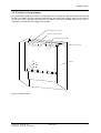
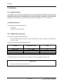
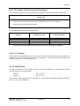
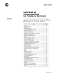
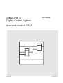
SIMADYN D
Digital Control System
User Manual
Interface module CS51
Edition 05.95
DK-Nr. 247142
User Manual, Interface module CS51
Edition
Edition status
1
Interface module CS51
10.93
2
Interface module CS51
03.94
3
Interface module CS51
10.94
4
Interface module CS51
05.95
Copying of this document and giving it to others and the use or
communication of the contents thereof is forbidden without express
authority. Offenders are liable to the payment of damages. All rights
are reserved in the event of the grant of a patent or the registration of
a utility model or design.
We have checked the contents of this Manual to ensure that they
coincide with the described hardware and software. However,
deviations cannot be completely ruled-out, so we cannot guarantee
complete conformance. However, the information in this document is
regularly checked and the necessary corrections included in
subsequent editions. We are thankful for any recommendations or
suggestions.
Contents
Contents
Warning information................................ ................................ ................................ ...................... 1
1. Ordering data................................ ................................ ................................ ............................ 3
2. Description................................ ................................ ................................ ................................ 3
3. Module design................................ ................................ ................................ ........................... 4
3.1. Mechanical aspects................................ ................................ ................................ .... 4
3.2. HW configuration................................ ................................ ................................ ....... 4
3.3. Function of the processor................................ ................................ ........................... 5
4. Interfaces................................ ................................ ................................ ................................ .. 6
4.1. Parallel interface................................ ................................ ................................ ........ 6
4.2.Serial interfaces................................ ................................ ................................ .......... 6
4.2.1. RS485 (SST1 interface)................................ ................................ ............... 6
4.2.2. TTY (20mA) / RS 232 (V.24) (SST2 interface)................................ ............. 7
4.2.2.1. TTY (20mA)................................ ................................ ........................ 7
4.2.2.2. RS232 (V.24)................................ ................................ ...................... 7
5. Installing the bus system................................ ................................ ................................ ........... 8
5.1. USS protocol ................................ ................................ ................................ ............. 8
5.1.1. Bus termination for USS protocol on CS51................................ .................. 9
5.2. SINEC L2 DP, SINEC L2 FMS................................ ................................ ................... 10
5.3. DUST6 bus................................ ................................ ................................ ................ 11
5.4. SINEC L1................................ ................................ ................................ ................... 12
5.5. Simple protocol (via a bus) ................................ ................................ ........................ 12
6. Installation guidelines................................ ................................ ................................ ................ 13
7. LEDs................................ ................................ ................................ ................................ ......... 14
8. Additional components................................ ................................ ................................ .............. 15
9. Technical data................................ ................................ ................................ ........................... 16
10. Interface pin assignments................................ ................................ ................................ ........ 17
10.1. Pin-outs of the RS 485 interfaces X5, X6................................ ................................ . 17
10.2. Pin-outs of the RS 485 interface X7................................ ................................ ......... 17
10.3. Pin-outs of the RS 232 / TTY interface X8................................ ................................ 17
10.4. Parallel interface X2 to the PT1/PT10 or the basic unit................................ ............. 18
10.5. Block diagram................................ ................................ ................................ .......... 19
10.6. Dimensional drawing and table showing connectors................................ ................. 19
10.7. Location diagram ................................ ................................ ................................ ..... 19
11. ECB instructions................................ ................................ ................................ ...................... 23
Siemens AG Dk-Nr. 247142
SIMADYN D Hardware User Manual
Edition 05.95
Warning information
Edition 05.95
Siemens AG Dk-Nr. 247142
SIMADYN D Hardware User Manual
Warning information
NOTE!
The information in this Manual does not purport to cover all details or variations in equipment, nor to provide
for every possible contingency to be met in connection with installation, operation or maintenance.
Should further information be desired or should particular problems arise which are not covered sufficiently for
the purchaser’s purposes, please contact your local Siemens office.
Further, the contents of this Manual shall not become a part of or modify any prior or existing agreement,
committment or relationship. The sales contract contains the entire obligation of Siemens. The warranty
contained in the contract between the parties is the sole warranty of Siemens. Any statements contained
herein do not create new warranties nor modify the existing warranty.
Warning information
WARNING!
Electrical equipment has components which are at dangerous voltage levels.
If these instructions are not strictly adhered to, severe bodily injury and material
damage can result.
Only appropriately qualified personnel may work on this equipment or in its
vicinity.
This personnel must be completely knowledgeable about all the warnings and
service measures according to this User Manual.
The successful and safe operation of this equipment is dependent on proper
handling, installation, operation and maintenance.
Siemens AG Dk-Nr. 247142
SIMADYN D Hardware User Manual
Edition 05.95
1
Warning information
Definitions
*
QUALIFIED PERSONNEL
*
DANGER
*
WARNING
*
CAUTION
*
NOTE
For the purpose of this User Manual and product labels, a „Qualified person“ is someone who is familiar with the
installation, mounting, start-up and operation of the equipment and the hazards involved. He or she must have
the following qualifications:
1. Trained and authorized to energize, de-energize, clear, ground and tag circuits and equipment in accordance
with established safety procedures.
2. Trained in the proper care and use of protective equipment in accordance with established safety
procedures.
3. Trained in rendering first aid.
For the purpose of this User Manual and product labels, „Danger“ indicates death, severe personal injury and/or
substantial property damage will result if proper precautions are not taken.
For the purpose of this User Manual and product labels, „Warning“ indicates death, severe personal injury or
property damage can result if proper precautions are not taken.
For the purpose of this User Manual and product labels, „Caution“ indicates that minor personal injury or
material damage can result if proper precautions are not taken.
For the purpose of this User Manual, „Note“ indicates information about the product or the respective part of the
User Manual which is essential to highlight.
CAUTION!
This board contains components which can be destroyed by electrostatic
discharge. Prior to touching any electronics board, your body must be electrically
discharged. This can be simply done by touching a conductive, grounded object
immediately beforehand (e.g. bare metal cabinet components, socket protective
conductor contact).
WARNING!
Hazardous voltages are present in this electrical equipment during operation.
Non-observance of the safety instructions can result in severe personal injury or
property damage.
It is especially important that the warning information in all of the relevant
Operating Instructions are strictly observed.
2
Edition 05.95
Siemens AG Dk-Nr. 247142
SIMADYN D Hardware User Manual
Ordering data
1. Ordering data
CS51: 6DD1660-0AH1
Communications module CS51
2. Description
The CS51 module is used to connect a SIMOVERT P 6SE12 or SIMOREG K 6RA24 to a higher level
automation, control or monitoring system. The interface uses one of the following protocols:
USS protocol
SINEC L2 DP
SINEC L2 FMS
Simple (point to point)
SINEC L1
3964R (data transmission procedure without RK512 or pre-header)
Simple (via a bus)
DUST6
Any of these protocols can be selected. This is described in the publication "Datenaustausch
zwischen SIMOREG K/SIMOVERT P - Geräten und Erweiterungsbaugruppen (Gerätereaktion)",
[Data transfer between SIMOREG K/SIMOVERT P units and expansion modules (units' response)]
order number 6DD1902-0GE0.
The module has three serial interfaces plus a parallel interface for connecting a 6SE12 / 6RA24 basic
module or PT1/PT10 technology board The exchange of data between the CS51 and the basic
module / technology board takes place via a Dual Port RAM.
Incoming and outgoing telegrams are processed by a NEC uPD70325 (V25plus) processor. The
firmware is held in EPROM.
Siemens AG Dk-Nr. 247142
SIMADYN D Hardware User Manual
Edition 05.95
3
Module design
3. Module design
3.1. Mechanical aspects
The interface module is 160 x 233.4 mm in size and occupies the first slot in the rack, where it is
screwed into place.
The modules are connected together using ribbon cables as described below:
Basic module <--> PT1/PT10 <--> CS51
Basic module <--> CS51 (no technology board)
A separate +24V power supply is required if a full CS51 configuration is being used.
3.2. HW configuration
The module comprises the following hardware components.
NEC uPD70325 (V25plus) processor
128 kbyte EPROM with firmware
128 kbyte RAM
2 kbyte Dual Port RAM
Watchdog monitor for Dual Port RAM
3 serial interfaces (RS485, TTY, RS 232)
1 parallel interface
4
Edition 05.95
Siemens AG Dk-Nr. 247142
SIMADYN D Hardware User Manual
Module design
3.3. Function of the processor
The uPD70325 (V25plus) processor is responsible for processing the data that passes between the
compact unit (basic unit and expansion modules) and the higher-level system. Data can be received
at any time. After it has been processed it is written to the Dual Port RAM. Data is only sent in
response to a request from the higher-level system.
Technology board PT1/PT10
Basic or control module
Communication board CS51
D12 D11
D9 D10
D8
Ribbon cable, 64-pole
X2
Subrack
D13 D3
D7 D5 D4
X5
X6
X7
X8
1
X9
2
Figure 1: Subrack layout
Siemens AG Dk-Nr. 247142
SIMADYN D Hardware User Manual
Edition 05.95
5
Interfaces
4. Interfaces
4.1. Parallel interface
The parallel bus is connected to interface X1 of the technology board (PT1/PT10) by the 64-pole
ribbon cable in slot X2. If a technology board is not present, the bus is connected to interface X100 of
the 6SE12 control module or interface X100 in the case of the 6RA24. In addition to carrying the data,
address and control buses, this interface also provides a power supply of +5V, +15V and -15V.
4.2.Serial interfaces
The module has three serial interfaces:
2 * RS485
RS232 (V.24) / TTY (20mA)
4.2.1. RS485 (SST1 interface)
There are two separate RS485 interfaces:
Connectors X5 and X6 are used to connect the DUST6 bus; for the connection to the SINEC L2
bus, X7 is used.
These interfaces support the following protocols:
Protocol
Transmission rate
Plug
USS
SINEC L2 DP
SINEC L2 FMS
DUST6
Simple protocol (via a bus)
300Bd - 38.4 kBd
max. 1.5 MBd
max. 1.5 MBd
117.6 kBd
4.8 kBd -38.4 kBd
X5, (X6)
X7
X7
X5, X6
X5, (X6)
The RS485 interfaces are isolated, with an external +24 V power supply provided on X9.
Please note
Only one protocol may be used at a time.
6
Edition 05.95
Siemens AG Dk-Nr. 247142
SIMADYN D Hardware User Manual
Interfaces
4.2.2. TTY (20mA) / RS 232 (V.24) (SST2 interface)
The TTY (20mA) and RS 232 (V.24) interfaces are situated in the 15-pole Sub-D connector X8.
Please note
Only one interface may be used at a time, either RS 232 (V.24) or TTY (20mA).
Only one protocol may be used at a time
These interfaces support the following protocols:
Protocol
Transmission rate
Physical interface
USS
SINEC L1
Simple protocol (point to point)
3964R
300 Bd - 38.4 kBd
9.6 kBd
1.2 kBd - 19.2 kBd
9.6 kBd
TTY, RS232
TTY *)
TTY, RS232
TTY, RS232
*) As this protocol uses the BT777 bus terminal, only the TTY interface is supported.
4.2.2.1. TTY (20mA)
There are two non-isolated current sources for the TTY interface. The transmitter and the receiver are
isolated. The maximum cable length is 100m at 19.2 kBd. A 4 core round screened cable should be
used (e.g. LICYC, 4 * 0.5, from. Metrofunk).
4.2.2.2. RS232 (V.24)
The RS 232 interface is not isolated. To drive the RS 232 interface, two wire jumpers must be
soldered in place in the plug housing.
Jumper 1:
Jumper 2:
Pin 2 -- Pin 15
Pin 9 -- Pin 11
The maximum cable length is 15m at 19.2 kBd. A 4 core round screened cable should be used (e.g.
LICYC, 4 * 0.5, from. Metrofunk).
Siemens AG Dk-Nr. 247142
SIMADYN D Hardware User Manual
Edition 05.95
7
Installing the bus system
5. Installing the bus system
5.1. USS protocol
Two-wire cable:
The bus is installed using a two-wire cable as illustrated below:
Bus termination 1)
Master
e.g. CP524
2
CS51/CS61
X5
X6
SM5
2
CS51/CS61
X5
X6
Slave
e.g. 6RA24
SM5
2
X5
Bus termination 1)
Figure 1: Installation of two-wire bus
1)
A bus termination must be present on the first and last node in the bus line.
The connection of the two-wire cable to plug X5 of the CS51 module is carried out as shown in
the diagram below:
9-pole sub D connector (SM5)
5 9
Bus cable from
preceding
bus node
Jumper 1
Jumper 2
6
2
1
Pin 1: RxD/TxDPin 6: RxD/TxD+
2
Bus cable to
next bus
node
Figure 2: Pin-out for connecting two-wire cable to plug X5
8
Edition 05.95
Siemens AG Dk-Nr. 247142
SIMADYN D Hardware User Manual
Installing the bus system
Note
Two wire jumpers must be soldered in the plug
Jumper 1:
Jumper 2:
Pin 6 -- Pin 9
Pin 1 -- Pin 5
5.1.1. Bus termination for USS protocol on CS51
If the CS51 module is the first or last node on the bus line, a bus termination must be fitted in plug S5
or S6 as shown below.
39 0 Ω
5 9
1 RS 485 T2 P5 EXT
150 Ω
7 M5 EXT
39 0 Ω
6
9 RS 485 T+
1
Figure 3: Bus termination for USS protocol
Siemens AG Dk-Nr. 247142
SIMADYN D Hardware User Manual
Edition 05.95
9
Installing the bus system
5.2. SINEC L2 DP, SINEC L2 FMS
Connection is made either via the SINEC L2 RS485 bus terminal or the SINEC L2 bus connection
plug to the 9-pole Sub D connector X7. When using the RS485 bus terminal, the capacitance of the
drop cable must be taken into account in relation to the Baud rate. Both the bus terminal and the bus
connection plug have terminating resistors that can be connected.
Notes on SINEC L2 and the components necessary to install a bus system can be found in the
SIMATIC S5 catalogue "Nachtrag April 1992 zum Katalog ST52.1" or the equipment manual
"SIMATIC S5 Dezentrales Peripheriesystem ET200", order number: 6SE5998- 3ET11.
Note:
The CS51 is a slave interface on SINEC L2 DP and SINEC L2 FMS.
CS51/CS61
SINEC L2 bus cable
2
X7
SINEC L2
bus connection plug
CS51/CS61
2
SINEC L2 bus cable
2
X7
Drop cable
SINEC L2
RS 485l
bus terminal
2
Figure 4: Connection to SINEC L2 bus via SINEC L2 bus connection plug and RS 485 bus terminal
10
Edition 05.95
Siemens AG Dk-Nr. 247142
SIMADYN D Hardware User Manual
Installing the bus system
5.3. DUST6 bus
The cable to the CS41 or the previous node on
the bus is connected to the 9-pole Sub-D
connector X5. The cable to the next node on
the bus is connected to X6. The previous node
on the bus may be either a CS51 module
situated in a compact unit, a CS61 module in a
SIMOVERT A4/P3 or a CS41 master module in
the SIMADYN D rack. The next node may also
be a CS51 module in a compact unit or a CS61
module in a SIMOVERT A4/P3. An SM7 bus
terminator must be fitted to connector X6 of the
last node on the bus.
The cables connecting the CS41 and CS51 or
the CS51 to another CS51 or a CS61 must be
made up to the correct length. The pin-out and
the type of cable for installing the DUST6 bus
can
be
found
in
the
publication
"Kommunikationsmodul CS41, Anschluß von
DUST6 und ET100U, Projektierungshilfe"
[Communications modules CS41, connection of
DUST6 and ET100U, Planning guidelines],
order number E31930-T8005-X-A1.
CS41
X5 or
X6 or
X7 or
X8
SM1.1
6
CS51/CS61
X5
SM5
SM5.1
X6
6
CS51/CS61
X5
SM5
SM5.1
X6
Figure 6: DUST6 bus configuration
CS51/CS61
6
X5
SM5
One each of parts kits SM1.1 and SM5 are
required for the connection cable between
CS41 and CS51, and one each of parts kits
SM5 and SM5.1 for the connection cable
between CS51 and CS51 or CS61.
SM7
X6
Figure 6: DUST6 bus configuration
5 9
As an alternative to the SM7 bus connection
plug, two 120Ω terminating resistors can be
soldered directly in the plug housing of plug
X5 on the last node. One resistor is soldered
between pins 1 and 9, the other between pins
5 and 6.
120 Ω
120 Ω
6
1
Figure 7: Connection of bus terminating
resistors
Siemens AG Dk-Nr. 247142
SIMADYN D Hardware User Manual
Edition 05.95
11
Installing the bus system
5.4. SINEC L1
Modules are connected to the bus through the SINEC L1 bus terminal BT777, which fits into the 15pole Sub-D connector X8. To enjoy all the features of the bus terminal, an external power supply is
required (P5EXT). See the technical description of the BT777 bus terminal for more information.
To connect the SINEC L1 bus terminal BT777, both threaded pins on plug X8 must be replaced by the
interlocking pins supplied.
SINEC L2 bus cable
CS51/CS61
Bus terminal
BT777
4
X8
P5EXT
Drop cable
4
Figure 8: Connection to the SINEC L1 bus using the bus terminal
5.5. Simple protocol (via a bus)
Four-wire cable
The bus has the same configuration and the same pin-out on plugs X5 and X6 as for the DUST6 bus.
Two-wire cable
The configuration of the bus and the bus terminations with a two-wire cable, as well as the pin-outs
on plug X5, are the same as for the USS protocol.
12
Edition 05.95
Siemens AG Dk-Nr. 247142
SIMADYN D Hardware User Manual
Installation guidelines
6. Installation guidelines
The following installation guidelines must be observed to ensure trouble-free operation of the serial
bus:
A potential equalisation conductor (min. 16 mm2) must be laid between the individual nodes.
This conductor must be connected to all the earth bars.
The screen of the bus cable must be well earthed as close as possible to the connector.
The SIMADYN D installation guidelines and the EMC guidelines must also be observed.
Siemens AG Dk-Nr. 247142
SIMADYN D Hardware User Manual
Edition 05.95
13
LEDs
7. LEDs
The LEDs D3, D4, D5 and D13 show whether data traffic is present on the serial send and receive
conductors of the RS485 and 20mA / V.24 interfaces.
LED
Status
Meaning
Remarks
D3
off / on
flickering / glowing
off / on
flickering / glowing
off / on
flickering / glowing
off / on
flickering / glowing
RS485 interface not sending
RS485 interface sending
RS485 interface not receiving
RS485 interface receiving
RS232 / TTY interface not sending
RS232 / TTY interface sending
RS232 / TTY interface not receiving
RS232 / TTY interface receiving
applies to X5, X6 and
X7
D13
D5
D4
applies to X8
LEDs D8 - D12 act as check indicators for the operating status of the processor and the specified
protocols.
LED
Status
Meaning
Remarks
D12
off, flickering
on
off, flickering
Transmission error in USS protocol on SST2
USS running error-free on SST2
Transmission error in DUST6- or USS
protocol
(RS485) on SST1
DUST6- or USS protocol (RS485) running
error-free on SST1
Transmission error in SINEL L1 protocol
SINEC L1 protocol running error-free
Transmission error in SINEC L2 protocol
SINEC L2 protocol running error-free
Processor fault
Processor running
applies to X8
D11
on
D9
D8
D10
off, flickering
on
off, flickering
on
off, on
flashing
applies to X5 and X6
applies to X8
applies to X7
LED D7 has no function.
14
Edition 05.95
Siemens AG Dk-Nr. 247142
SIMADYN D Hardware User Manual
Additional components
8. Additional components
The following additional components are required when configuring the bus for DUST6, USS and
simple protocol on the RS 485 interface (see Catalogue DA99, October 1990 supplement):
Description
MLFB
Parts kit SM1.1
Parts kit SM5
Parts kit SM5.1
Bus terminator SM7 (DUST 6)
6DD1680-0AB1
6DD1280-0AF0
6DD1680-0AF1
6DD1680-0AH0
The following additional components are required for a SINEC L2 bus:
Description
MLFB
Bus terminal RS485, 1.5 m cable
Bus terminal RS485, 3 m cable
SINEC L2 bus connector
6GK1500-0AA00
6GK1500-0AB00
e.g.6ES5762-1AA12
Refer to the catalogues "SINEC Industrial Communications Networks Catalog IK 10.1993" and
"ET200 and ET100U Distributed I/O Systems Catalog ST54.2" for other components for the SINEC
L2 bus.
The following additional components are required for a SINEC L1 bus:
Description
MLFB
Bus terminal BT777-0 (1 m cable)
Bus terminal BT777-1 (2 m cable)
6ES5777-0BB00
6ES5777-1BC00
Siemens AG Dk-Nr. 247142
SIMADYN D Hardware User Manual
Edition 05.95
15
Technical data
9. Technical data
Insulation group
Ambient temperature
Storage temperature
Humidity rating
Altitude rating
Mechanical duty
Enclosure systems
Dimensions
Module width
Weight
Power consumption
16
A according to VDE 0110 $ 13 Group 2 at 24 V-, 15 V-, 5 V0 to +55 ° C with self-ventilation
-40 to + 70 ° C
F according to DIN 40040
S according to DIN 40040
Installed in static units that may vibrate
MKT swing-out rack
160 * 233.4 mm
1 slot in MKT rack
0.4 kg
P5
0.5 A
P15
50 mA
P24 external 100 mA
Edition 05.95
Siemens AG Dk-Nr. 247142
SIMADYN D Hardware User Manual
Interface pin assignments
10. Interface pin assignments
10.1. Pin-outs of the RS 485 interfaces X5, X6
X5 (9-pole, Sub-D female connector), X6 (9-pole, Sub-D male connector)
1
2
3
4
5
6
7
8
9
RS485TP5EXT
M5EXT
M5EXT
RS485RRS485R+
M5EXT
M5EXT
RS485T+
Send signal 5V external
External ground
External ground
Receive signal Receive signal +
External ground
External ground
Send signal +
10.2. Pin-outs of the RS 485 interface X7
X7 (9-pole, Sub-D female connector)
1
2
3
4
5
6
7
8
9
----PRFTR +
RTS
M5EXT
P5EXT
--PRFTR RTS
----Receive and send signal +
Ready to send
External ground
5V external
--Receive and send signal Ready to send
10.3. Pin-outs of the RS 232 / TTY interface X8
X8 (15-pole, Sub-D female connector)
Pin
TTY (20mA)
RS 232 (V.24)
1
2
3
4
5
6
7
8
9
10
11
12
13
14
15
--RTTY- (Current loop Receive -)
----M (Earth)
TTTY+ (Current loop Send +)
TTTY- (Current loop Send -)
--RTTY+ (Current loop Receive +)
--Jumper to pin 15
--RXD (Receive signal RS 232)
M (Earth)
------Jumper to pin 11
TXD (Send signal RS 232)
Jumper to pin 9
M (Earth)
----Jumper to pin 2
20mA1 (Current source 1)
M (Earth)
20mA2 (Current source 2)
--M (Earth)
Siemens AG Dk-Nr. 247142
SIMADYN D Hardware User Manual
Edition 05.95
17
Interface pin assignments
10.4. Parallel interface X2 to the PT1/PT10 or the basic unit
X2 (64-pole ribbon cable to PT1/PT10 or basic unit/control module)
Pin
Function
Pin
Function
1
3
5
7
9
11
13
15
17
19
21
23
25
27
29
31
33
35
37
39
41
43
45
47
49
51
53
55
57
59
61
63
AD0
AD1
AD2
AD3
AD4
AD5
AD6
AD7
AD8
AD9
AD10
AD11
AD12
AD13
AD14
AD15
ALE
L_WR
L_RESET
L_RD
L_READY
L_BHE
--SYNC
ME
----ME
--P5
P5
P5
2
4
6
8
10
12
14
16
18
20
22
24
26
28
30
32
34
36
38
40
42
44
46
48
50
52
54
56
58
60
62
64
M
M
M
M
M
M
M
M
M
M
M
M
M
M
M
M
ME
ME
ME
ME
ME
ME
ME
ME
--L_CSPER1
L_INT
L_STAT1E
----P15
N15
18
Edition 05.95
Siemens AG Dk-Nr. 247142
SIMADYN D Hardware User Manual
Interface pin assignments
10.5. Block diagram
Figure 9: Block diagram
10.6. Dimensional drawing and table showing connectors
Figure 10: Dimensional drawing and table showing connectors used
10.7. Location diagram
Figure 11: Location diagram
Siemens AG Dk-Nr. 247142
SIMADYN D Hardware User Manual
Edition 05.95
19
Interface pin assignments
64-way ribbon cable to PT1 or DPM
Address driver
Data driver
Reset logic
Control signals
Dual port RAM
1 k * 16
Quartz
oscillator
20 MHz
Arbitration / DPR controller
Address bus
Processor
Data bus
Control bus
uPD 70325 ( V25plus )
LED display
Chip select decoder
Watch dog
RAM
EPROM
128 kbyte
Quartz
oscillator
24 MHz
128 kbyte
Interface controller
SPC
Diagnostic plug
Interface
RS232 / TTY
P5EXT
X8
X9
15-way Sub D
Interface
Interface
RS485
RS485
X5
2-way
X6
9-way Sub D
9-way Sub D
X7
9-way Sub D
External power
supply
Figure 9: Block diagram
20
Edition 05.95
Siemens AG Dk-Nr. 247142
SIMADYN D Hardware User Manual
Interface pin assignments
Printed circuit board
X5
X6
X7
Component side
233.4
X8
X9
173
17
Connector
Name
Type (standard)
Function
X5
Socket connector 9way
B009FS-C1D1S DIN
41652
Serial interface RS485
X6
Plug connector 9-way
Serial interface RS485
X7
Socket connector 9way
B009MS-C1D1S DIN
41652
B009FS-C1D1S DIN
41652
X8
Socket connector 15way
B015FS-C1D1S DIN
41652
Serial interface
RS232/TTY
X9
Plug connector 2-way
MSTBA 2,5/2-G-5,08
(Phönix)
24 V - external
Serial interface RS485
Figure 10: Dimension drawing and table showing connectors used
Siemens AG Dk-Nr. 247142
SIMADYN D Hardware User Manual
Edition 05.95
21
Interface pin assignments
Figure 11: Location diagram
22
Edition 05.95
Siemens AG Dk-Nr. 247142
SIMADYN D Hardware User Manual
ECB instructions
11. ECB instructions
Components which can be destroyed by electrostatic discharge (ECB)
Generally, electronic boards should only be touched when absolutely necessary.
The human body must be electrically discharged before touching an electronic board. This can be
simply done by touching a conductive, grounded object directly beforehand (e.g. bare metal cubicle
components, socket outlet protective conductor contact.
Boards must not come into contact with highly-insulating materials - e.g. plastic foils, insulated
desktops, articles of clothing manufactured from man-made fibers.
Boards must only be placed on conductive surfaces.
When soldering, the soldering iron tip must be grounded.
Boards and components should only be stored and transported in conductive packaging (e.g.
metalized plastic boxes, metal containers).
If the packing material is not conductive, the boards must be wrapped with a conductive packing
material, e.g. conductive foam rubber or household aluminum foil.
The necessary ECB protective measures are clearly shown in the following diagram.
a = Conductive floor surface
b = ECB table
c = ECB shoes
Seated
Siemens AG Dk-Nr. 247142
SIMADYN D Hardware User Manual
d = ECB overall
e = ECB chain
f = Cubicle ground connection
Standing
Edition 05.95
Standing/sitting
23
ECB instructions
24
Edition 05.95
Siemens AG Dk-Nr. 247142
SIMADYN D Hardware User Manual
ECB instructions
Drives and Standard Products
Motors and Drives Systems Group
Postfach 3269, D-91050 Erlangen
Siemens AG Dk-Nr. 247142
SIMADYN D Hardware User Manual
System-Based
Technology
Edition 05.95
25