1
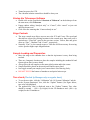
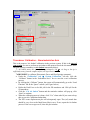
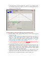
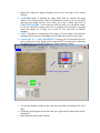
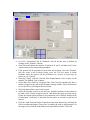
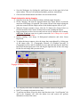
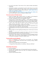
Instruction for Hysitron TI 950 Triboindenter (For Quasi Static Indentation) To schedule training on the SPM, contact Gajendra Shekhawat ([email protected], 1-3204/ 847-650-2918. In case you could not find the Manager, contact: Supinda Watcharotone ([email protected]). Warnings Never touch the bottom of the transducer and scanner Contact facility manager for changing the transducer, probe or tip-area calibration. Users are not allowed to change the components of the system as they are very very delicate. When tip encounters high force against it, the software automatically perform emergency STOP and all icons are grayed out. In such cases, just above the optical microscope, you will see a YELLOW knob with labeled up and down position. Move it upwards as per on-screen instructions and enable the motor followed by home z-motor. Transducer and diamond Probes We have two transducers: 1D and 2D. 2D is used to perform Quasi static indents, scratch tests and 1D is used for nano DMA and modulus mapping. 2D transducer is the default transducer on the system. Please see the manager if you need to change the transducer, change the probe or observe off values of quartz (Er=69.55 GPa, H=9.25 GPa). Indenter probes are very costly item and we have three different types of probes for specific applications 1. Berkovitch probe for normal indents 2. Cube corner probes for sharp indents 3. Biological probe for soft matters and indents in liquids Users can see the manager if they want to use the specific probes for their applications. Request has to be made 24 hrs in advance as tip-area calibration will be carried out each time the probe is changed. Switching on Turn on the (top) piezo and (bottom) stage controllers. Turned on power for CCD. The vibration isolation control box should be always on. Startup the Triboscope Software Double click on the icon labeled “Shortcut to Triboscan” on the desktop or from the start menu, click Triboscan. Popup window asking “Analysis only” or “Cancel”, click “cancel” or just wait until clock turns zero. Click Ok to the warming that “Camera already in use”. Stage Controls The stage controls area allows users to move the X/Y and Z axes. The speed and direction are selected by clicking locations in the controls area. Inner area (red) is equivalent to “Ultra fine” speed in the previous version. Yellow, blue and green areas are “Fine”, “Medium” and “Coarse”, respectively. Normally “Fine” is slow enough to move. Ultra fine will be necessary for moving at slow speed at higher optic magnifications. Sample Loading and Preparation Move the stage to the chamber door so that the tip/scanner is away from being touched. There are 4 magnetic locations to place the samples including the standard Al and Quartz (please don’t remove them). Always place the tall samples on the most right location and in the corner. Sample should be placed on the metal pucks and be super glued. Just wiggle around your sample just to ensure that it is not moving freely. DO NOT TOUCH the bottom of transducer and optical microscope. Tare check (Checked by Manager only on regular basis) To see the tare value, click the “Calibration” tab “System Calibration” sub tab In the “System Parameters” box, click the “Update” button. (See Figure below, tare value is highlighted) The updated tare value is displayed next to the “Update” buttom. Tare value should be around – (240 + tip weight) for the 2D transducer and –(400 + tip weight) for the 1D transducer. Air Indent Transducer Calibration – Nanoindentation Axis This is the same as “Air Indent” calibration in the previous system. If this is the start of your session, be sure to perform an air indent at this point to check the electrostatic force and plate spacing constants (see Air Indent instructions below). Air Indent moves the tip only by approximately 3-4 m. As long as the tip is sufficiently away from the sample surface, the tip will not indent! *AIR INDENT (to calibrate Electrostatic Force and Plate Spacing constants): Under the “Calibration” tab “System Calibration” sub tab, click the “Calibrate” button in the “Indentation Axis” box to start the z-axis calibration process. By clicking the “Calibrate” button, the system will automatically go to the “Load Function” tab the “Quasi” sub tab. (see Figure below) Define the Peak Force to be 600 N for the 2D transducer and 1200 N for the 1D transducer. Click the “Cal Air Indent” button and the reminder window will pop up, click “Start” to continue. When the calibration process is done, click “Yes” when asked if you want to keep this as your Air Calibration Indent data. The ESF versus displacement plot will subsequently open. The (red) actual data should be very close to the fitted linear (blue) curve. If not, repeat the Air Indent process. If the curves agree well, close the plot window. All the data points will be shown under the “Analysis” tab “Indent” sub tab. The data points should scatter around 0 µN within 5 µN and the displacement is between 3-4.5 µm. Repeat if not! Setting Safety Limits and Defining Sample Boundaries Load the sample. Tallest samples should always be placed nearest the optics column on the right. Under the “Sample Navigation” tab, using the stage controls area, move the X, Y and Z axes of the sample stages to locate a corner or edge (for transparent samples) or center of the sample (opaque samples) and adjust Z-axis for the corner or edge of the sample to be in focus. CHECK the X-Y SAFETY DISABLED. DO NOT CHECK THE Z-SAFETY. It is important that the surface of the sample be in focus when the boundary is created, especially when the sample is translucent as the bottom surface can easily be mistaken for the upper surface resulting in tip damage. Once focused, just go little bit outside of the corner or edge and click the “New Sample” button. Select a name for the sample and click OK. Click the “Pos. Add” button to add a position to the sample boundary. Square/rectangular shaped samples boundary can be defined by four corner points while circular samples boundaries should be defined by multiple points. Using the X/Y-axis stage controls, move the optics over a different corner or other edge location and click “Pos. Add” until the entire sample boundary is created. Repeat the steps for each additional sample or sample boundary area. Right-click within the sample boundary area to move the optic to the desired location. ANOTHER option of defining the safety limits both for smooth and rough surfaces: For smooth surface, instead of defining the corners, just use the optics and bring the sample field of views where you want to indent and click on CHECK BOUNDARY. It will create the small area where you can indent within. If you have ROUGH sample and focus is changing from position to position across the sample, try to bring area in field of view and click on CHECK boundary. NOTE: Transducer is coming from left to right, so if your sample is non-uniform in height, please make sure that higher end of rough side remains on your right. Uncheck the X-, Y safety DISABLED. If testing will be performed from the optic position, the actual height of the sample MUST be measured by adjusting the sample to be in focus and clicking the “Quick Approach” button. X/Y and Z-axis stage controls You can put multiple samples at the same time and define the boundary for all of them. Performing quick approach will allow the tip to approach the sample faster before indentation. Quick approach all the other samples. Performing Indentations and Imaging There are 4 different ways to perform indentation tests. A single indent can be made either from the optic location or from the center of an imaging scan window. The through optic indent is generally for the samples that are homogeneous while the imaging indent is useful when user wants real time image of the indented location. Multiple indents can be made by setting up automated methods or piezo automation. The latter are always set up and executed from the imaging position when the probe is in contact to the surface while the latter from the optical position. Each indentation procedure is explained as follows. Single Indentation on Optical Position Move the optics over a desired sample location. Go to the “Load Function” tab “Indent” sub tab to define the load function. Open the trapezoid load function file and modify the parameters as desired by left-clicking the segment. Click the Perform Indent at the bottom of the load function window to start the test. Save the result file. Click Execute Fit to calculate the reduced modulus and hardness from unloading data. Making Array of Indents on Optical Position Automated methods are always configured and executed from either current or predefined optical positions. This automated section can be found under the “Automation” tab “Methods” sub tab. The left side of the “Methods” sub tab is nearly identical to the “Sample Navigation” tab to allow the user to navigate the sample space, define samples and perform other functions without the need to toggle between tabs. The right side of the “Methods” sub tab consists of three side tabs (Setup, Patterns and Positions) that are useful for performing multiple automated tests. Go to the “Automation” tab “Methods” sub tab. Set the array of indents by clicking on the “Patterns” side tab. Select Grid and choose the number of indents in X and Y and then click Create. Assign a name to the pattern when prompted. If the pattern will be performed at more than one location, select the “Position” side tab, create a new Position Group, move the X/Y-axis stages to define Positions where the pattern will be performed (not required if performing the pattern at one location). Select the “Setup” side tab. Click the New Method button, select a name for the method. The Method Type is Indent. Set the Base File Name for saving the files. Each file will automatically have a number assigned at the end of the file name starting at 0000. Select the directory to save the files by clicking the Browse button. Select the Pattern that is previously created. Under the Position section, in case there are multiple positions for the pattern to be made, select “Pattern Using Position in” and choose the group you want to test. If only the current optical position to be performed, select “Pattern, Starting at the Current Optic”, total times 1, and make sure the optics are located over the area of interest. Click the Load Function button. Load the desired load function by selecting the Select load function button. Choose how to modify the load or displacement over the range of tests with the radio buttons and start/end load values. Click OK. Save the Workspace by clicking the small down arrow in the upper left of the main window. This saves all automated methods, positions, and patterns. Click the Start Method button and follow on-screen instructions. Single Indentation during Imaging Optically locate the area of interest within a defined sample boundary. On the “Imaging” tab click the Approach button (See Figure below) or from the menu bar click Engage Approach. The system will move the stages to bring the probe into contact with the sample surface at the default setpoint value of 2μN. When the Progress window closes, click the Go button (See Figure below) or from the menu bar click Control Start Scan to start scanning the surface. Image parameters such as scan size and scan rate can be changed while scanning. 0.5Hz and 10 micron scan size is good to start with. Don’t change the set point force and integral gain values. During scanning, click Image Background subtraction and select Linear Regression. To adjust the image contrast, select the image that want adjusted by clicking one of the image types: Tf (Topography forward), Gf (Gradient forward), Tr (Topography reverse) and Gr (Gradient reverse) and click and drag the dark blue bars below the histogram plot. Click and drag the light blue bar to move the range. Do this for each image that you want to use. Engage Withdraw Go Stop Indent You can play with offsets to shift the image if current location is not good. DON’T use sample navigation arrows here. To perform an indent, set up the desire load function in the “Load Function” tab and in the “Imaging” tab, click the indent icon and system will perform indentation exactly in the center. Save the file when done. Click Execute Fit for reduced modulus and hardness calculations. After indent is complete, tip automatically scans the surface and you can view the indentation mark and capture the image. Images can be saved by clicking the Camera icon or Image Capture from the menu bar. MAKE SURE that you define your capture directory here. To leave imaging mode, click Stop button to stop scanning and withdraw the probe from the sample surface by clicking the Withdraw button. Piezo Automation for Multiple Indents During the Imaging mode, while the probe is in contact to and scanning the surface, go to the “Load Function” tab to set up the load function. Go to the “Automation” tab “Piezo Automation” sub tab. Select the type of Script Mode to perform: 1.) Array Script will perform a rectangular array of tests over the sample surface or 2.) Click Script will display the current in-situ image and allow the user to left-click to select testing locations. If choose Array Script, define the number of tests to perform in X and Y and distance between each indent. If choose Click Script, left click the desired locations on the displayed image to define the test locations. Click the Run Piezo Automation button, the system will automatically stop scanning and move the probe to the center of the image. When prompted, select a directory and click OK. Select a base file name and click OK. When prompted, enter the beginning and ending forces for the array of tests and click OK. When the piezo automation has completed, the software will return to the Imaging tab and the data files will be saved to the selected directory. If the Stay In Contact option was not selected, the probe will Disengage from the sample surface. User can either continue Imaging by clicking the Engage button or terminate the Imaging by clicking the Withdraw button. Save and Access the Results Users are encouraged to save their files in the directory C:\Program Files\Hysitron\Triboscan\Data. This folder can be accessed by clicking “Shortcut to Data” on desktop. For the previous results before the system upgrade, C:\Program Files\Triboscan\Data or on desktop or “Shortcut to Old Data”. Shut Down Procedure Save the Workspace. Close the software and the system will automatically home the stage and optics. Shut down the controllers in the reverse order. The controllers are labeled with numerical numbers. Sign off using FOM login software. Trouble Shooting Procedures Tip-Optics Calibration (Needed for precise indent location or when it takes too long to approach the surface) If the indentation marks are way off from where it supposed to be, tip-optics distance should be re-calibrated by creating an H pattern on aluminum. Define sample boundary for aluminum and DO NOT perform quick approach. Optically focus the surface where the H pattern will be easily found. Ensure that the triangle load function is opened in the Load Function tab. Go to the “Calibration” tab “Stage Calibration” sub tab “Tip to Optic Calibration” button (near the bottom left) New “H” Pattern button. The software will prompt the user that the Z Safety is disabled and will move over a defined sample space. Click OK. When prompted, enter a peak force of 8,000 μN and click OK. The system will move the sample under the probe. When prompted, manually lower the Z-axis until the probe is approximately 1mm above the sample. And Click OK. The system will automatically approach the surface and make seven indents in the shape of an H. After the pattern is done, the system will move the location back to under the optics. Locate the H pattern that is recently made using the X/Y-axis stage controls and place the cross hair (x) on the center indent of the H. Click OK. The system have now proper tip-optics calibration. It is recommended to perform an additional indent between the legs of the H to avoid the confusion with the future indent.