1
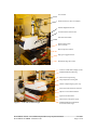
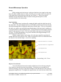
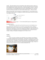
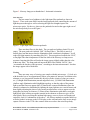
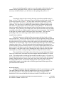
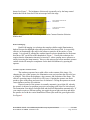
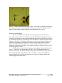
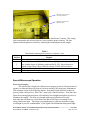
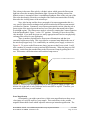
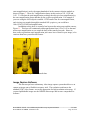
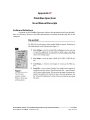
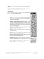
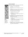
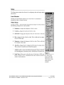
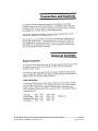
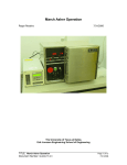
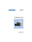
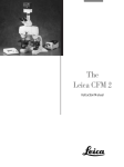
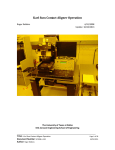
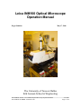
Leica INM100 Optical Microscope
Operation Manual
Roger Robbins
May 17, 2006
The University of Texas at Dallas
Erik Jonsson School of Engineering
______________________________________________________________________________________
DOCUMENT TITLE: Leica INM100 Optical Microscope Operation Manual
5/17/2006
DOCUMENT NUMBER: SU2006-LI-001
Page 1 of 28
Leica INM100 Optical Microscope
Operation Manual
Roger Robbins
5/17/2006
C:MyDocuments\CleanRoomGeneral/Equipment/OoticalMicroscopes/INM100/INM100Manual.doc
Table of Contents
Table of Contents................................................................................................................ 2
Leica INM100 Optical Microscope Operation Manual ...................................................... 4
Purpose............................................................................................................................ 4
Introduction..................................................................................................................... 4
Microscope Description .................................................................................................. 4
General Microscope Operation ................................................................................... 6
Startup ..................................................................................................................... 6
Stage Positioning .................................................................................................... 6
Objective Lens Selection ........................................................................................ 6
Lighting................................................................................................................... 7
Lamp Power ........................................................................................................ 7
Filter Selection .................................................................................................... 8
Viewing................................................................................................................... 8
Focus ................................................................................................................... 9
Bright Field Imaging........................................................................................... 9
Dark Field Imaging ........................................................................................... 10
Condenser Aperture Contrast Control .............................................................. 10
Interference Contrast Imaging .......................................................................... 11
Special Microscope Operation.................................................................................. 12
Fluorescence Imaging ........................................................................................... 12
Extra Magnification .............................................................................................. 13
Image Capture Software ............................................................................................... 14
Basic Image Capture Procedure............................................................................ 15
Conclusion .................................................................................................................... 15
Appendix A*..................................................................................................................... 16
Servicing and Maintenance........................................................................................... 16
The Most Frequent Faults in Microscopy................................................................. 16
Uneven Illumination ................................................................................................. 16
Flat Images................................................................................................................ 16
Un-sharp Patches in the Microscopic Image ............................................................ 17
Unnatural Contrast .................................................................................................... 17
______________________________________________________________________________________
DOCUMENT TITLE: Leica INM100 Optical Microscope Operation Manual
5/17/2006
DOCUMENT NUMBER: SU2006-LI-001
Page 2 of 28
Lack of Fine Details because useful Magnification has been Exceeded .................. 17
Appendix B* ..................................................................................................................... 18
FlashBus Spectrum ........................................................................................................... 18
User Manual Excerpts....................................................................................................... 18
Software Definitions ..................................................................................................... 18
Appendix C* ..................................................................................................................... 23
Reference Material for Video Camera.......................................................................... 23
______________________________________________________________________________________
DOCUMENT TITLE: Leica INM100 Optical Microscope Operation Manual
5/17/2006
DOCUMENT NUMBER: SU2006-LI-001
Page 3 of 28
Leica INM100 Optical Microscope
Operation Manual
Roger Robbins
5/17/2006
C:MyDocuments\CleanRoomGeneral/Equipment/OoticalMicroscopes/INM100/INM100Manual.doc
Purpose
The UTD Clean Room has purchased a new high performance optical Microscope
from Leica, Inc. It is a manually operated microscope and is called the INM100. This
document, gives brief operating instructions on how to physically operate our particular
microscope. General technical background information on how a microscope works is
contained in a lengthy document produced by Florida State University and can be found
on their web site at http://micro.magnet.fsu.edu/primer/ .
Introduction
The INM100 is a semi-automatic, high-performance optical microscope
designed for the Semiconductor Industry. It is equipped with a nominal CCD camera and
a computer system to capture the images. There is a large screen LCD monitor in the
table with which to view and capture the images, and a camera output LCD screen
mounted on the wall behind the large screen. The microscope is specially configured
with an Ultra Violet Fluorescent module that will enable it to produce pseudo selfilluminated (fluorescent) images of certain organic films that may be found on samples
such as photoresist, etc. The microscope is somewhat complicated with many manual
knobs to turn, some combinations of which will produce total darkness through the
lenses. Therefore this document should serve as a solace of understanding in the midst of
confusion and perhaps darkness.
Microscope Description
Labeled photos of both sides of the microscope are shown in Figures 1 and 2. It
operates basically like this: you look through the eyepieces to see a magnified image of
your sample placed under the objective lenses on a manual mechanical stage illuminated
by a mercury lamp at the rear of the microscope stand. This microscope utilizes reflected
light only, compared to the INM200 microscope which can use transmitted light also
(good for photomask viewing). Focus is achieved by rotating the stage focus knob and
moving the stage with the manual drive knobs at the lower right side of the stage. The
light intensity is controlled by the thumbwheel on the front face of the microscope below
the stage. The other controls manage the more subtle capabilities of the microscope and
will be described individually below.
______________________________________________________________________________________
DOCUMENT TITLE: Leica INM100 Optical Microscope Operation Manual
5/17/2006
DOCUMENT NUMBER: SU2006-LI-001
Page 4 of 28
CCD Camera
Zoom transfer lens (Vario TV adapter)
Variable Magnification Dial
Contrast Function Selector Dial
Filter Selection module
Wafer Rotation Table
(since removed)
Microscope Power Switch
Stage gear-engagement lever
Mechanical Stage drive knobs
Figure 1. Right side of Microscope
Location of small Video display on wall
Standard Illumination Housing
Fluorescence lamp housing
Lamp Adjustment Viewing Port
Tiltable compensating Eyepiece Assy
Focus Knob with Sensitivity Selection
Objective Lens Selection Buttons
Aperture selection button
Fluorescence Lamp power supply
Figure 2. Left side of microscope
Standard Illumination adjustment –
on front face below stage
______________________________________________________________________________________
DOCUMENT TITLE: Leica INM100 Optical Microscope Operation Manual
5/17/2006
DOCUMENT NUMBER: SU2006-LI-001
Page 5 of 28
General Microscope Operation
Startup
Before turning on the microscope, make sure that there is no sample on the stage
that will collide with the objective lenses. Find the power switch on the lower right rear
of the main body of the microscope and flip it on, (Figure 1). This powers up the
standard mercury illumination lamp for normal viewing and also powers on the
electronics that drive the microscope.
Stage Positioning
The manual stage is positioned by turning the knobs under the right front side of
the stage table. The gear-engagement lever arm should be pushed away from [to the side
of] the positioning knobs to engage the knob gears with the stage. The lever arm pushed
the other way enables easy and rapid manual positioning of the stage (just by pushing it),
to an approximation of the intended location. The upper knob moves the stage in and out
relative to the operator (Y-Axis). The lower knob moves the stage to the left and right
(X-Axis). The knob positioning is very precise and fine, allowing positioning of very
small objects into the field of view.
With the sample in place on the stage, drive the stage manually to position the
sample under the active objective lens. Make sure that there will be no collision between
the objective lens and the sample – never force anything.
Stage Drive Selection lever – Free Position
Stage Drive Selection lever – Engaged Position
Y-Axis Stage Drive knob
X-Axis Stage Drive knob
Figure 3. Stage drive engagement lever positions: Right – freewheeling, Left – Gears
engaged.
Objective Lens Selection
To avoid collisions between the sample and the lenses lower the stage using the
focus knobs to clear the lenses by a large margin. The objectives are mounted on a
motorized rotating “nose-piece” that can be rotated to select the objective lens giving an
appropriate magnification. The higher the magnification, the closer the lens comes to the
______________________________________________________________________________________
DOCUMENT TITLE: Leica INM100 Optical Microscope Operation Manual
5/17/2006
DOCUMENT NUMBER: SU2006-LI-001
Page 6 of 28
sample. The lenses and nose-piece are designed so that when the nosepiece rotates to a
new magnification, the image is still in focus. Therefore the operator must start with the
lowest magnification (widest separation between lens and sample), and focus. After the
low power focus is accomplished, the lenses may be rotated to higher power using the
lens selector buttons just to the rear of the left focus knob, Figure 3. These two (red)
buttons electronically rotate the nosepiece to change objectives: The top button rotates
the nosepiece from low power to high power and the bottom button rotates the nosepiece
in the opposite direction.
Z-Stage Max Height Lock
Coarse Focus
Fine Focus
Figure 4. Focus knob and (Red) objective change buttons.
WARNING NOTE:
One should never rotate the lenses from the lowest power to the highest power.
The reason for this is that the lower power lens has a large depth of focus, making it
difficult for the operator to achieve exact focus, but the higher power lens has much less
depth of focus, and requires a much closer sample-lens separation. If the operator has set
an imprecise focus separation on low power, the high power lens could rotate into the
sample, crushing it and perhaps damaging the lens or rotator as well.
Lighting
Lamp Power
Since our normal eyesight has great difficulty seeing anything in total darkness,
we need light to illuminate the expected sample. The Mercury vapor lamp for standard
viewing is located at the upper rear of the microscope body. It will light up when we turn
on the microscope. Its intensity is controlled by the little horizontal thumbwheel control
knob located on the front face of the lower microscope body under the stage. Rotate it to
a numerical value of about 5 to 8 for a nominally illuminated field.
______________________________________________________________________________________
DOCUMENT TITLE: Leica INM100 Optical Microscope Operation Manual
5/17/2006
DOCUMENT NUMBER: SU2006-LI-001
Page 7 of 28
Figure 5. Mercury lamp power thumbwheel – horizontal orientation.
Filter Selection
The last control over brightness is the light input filter pushrods as shown in
Figure 6. These rods rotate filters into the lamp input path, thus controlling the amount of
light that passes through as well as selecting the light wavelengths input to the
microscope optics. By the way, these are the pushrods located on the upper right rear of
the microscope body as seen in Figure 1.
Figure 6. Light input Filter Selection pushrods.
There are three filters in this bank. The rear push-rod with no plastic ID cap is
empty. The next push-rod is labeled “Diff.” (diffuser filter). This filter is merely a
frosted glass lens that insures that the illumination field is uniform in brightness. It will
reduce the light intensity by something like 20%. The next push-rod controls the “DLF,”
or Daylight Filter that compensates for the blue shift of the Mercury arc lamp source
spectrum. Inserting this filter will make the image appear slightly redder than the color
without any filter. The front push-rod inserts the Blue Filter labeled “BG 20,” that
“accentuates the borders of the spectrum,” according to the instruction manual. It makes
the image appear with a bluish hue.
Viewing
There are many ways of viewing your sample with this microscope: (1) Look at it
with the naked eye to see approximately where your pattern of interest is in relation to the
substrate so you can position it under the objectives in the vicinity of what you want to
see, (2) Bright field illumination (normal magnified view), (3) Dark Field illumination
(shallow angle illumination which highlights topology so that the edges of the pattern
light up and the flat areas appear dark, (4) Interference contrast illumination where the
contrast is enhanced or diminished by splitting the input light into two coaxial beams and
then slightly adjusting the phase of one causing an interference color to appear over the
image thus increasing its contrast, (5) Fluorescence illumination with short wavelength
light (black light) causing an organic material in the substrate to fluoresce (give off its
own light by down converting the incident high energy waves to lower wavelength (red
emission), and (6) Combinations of the above. All of these methods except the naked eye
will also produce an image on the LCD display on the wall and on the large screen image
capture software via the CCD video camera in the tower above the microscope body.
______________________________________________________________________________________
DOCUMENT TITLE: Leica INM100 Optical Microscope Operation Manual
5/17/2006
DOCUMENT NUMBER: SU2006-LI-001
Page 8 of 28
In any case look through the eyepieces to see the sample, while driving the stage
around with the right hand to locate your area of interest and adjusting the focus as
necessary with the left hand – you don’t have to do anything with your feet. ☺
Focus
Focusing the image involves moving the stage up and down until the image is
sharp – in focus. The Z-axis of the stage (focus) is driven by the dual knob on both sides
of the microscope base, Figure 4. The focus knob set has three functions: 1) coarse
focus, 2) fine focus, and 3) max stage height lock to protect samples and lenses from
collisions. The coarse focus is controlled by rotating the large diameter knob section.
This allows the stage height to be moved rapidly over long distances. The fine focus
knob is the smaller diameter knob that turns inside of the larger diameter coarse portion
of the knob. This is the tricky part of fine focus. If the fine focus knob section is pushed
(coaxially) to the left, one rotation equals 80 microns of z-axis movement. If it is pushed
to the right, one rotation equals 20 microns of stage z-movement. This extra fine
positioning of the z-axis of the stage enables better control of focus for high
magnification conditions.
The black ring next to the body of the microscope at the focus knob set is the
stage z-height lock. This prevents the stage from moving too high and causing collisions
with the lenses as they are rotated. This is used in cases where the samples are thick and
the stage needs to be low in order to achieve the proper focus gap between the sample
and the lens. If someone then wants to look at a thin sample, the stage will not drive high
enough to achieve focus. This will require the black ring about the focus knobs to be
loosened and the focus knob rotated to achieve focus with a high magnification lens and
then re-locked. This however puts the stage at risk from the next user who may have a
thick sample. If one fails to take care in adjusting the stage for proper focus, the stage
and sample may collide, causing breakage of either the sample or the lens or both.
The standard focus lock height is that which achieves proper high magnification
focus for a 4 inch wafer, since most users have samples about the thickness of a 4 inch
wafer. This setting results in a thin gap between the lens and the stage, so if you have a
thick sample, please take extra care with the system by lowering the stage, inserting your
sample, setting the objective lens to a low power away from your sample, then moving
the sample under the lens, and carefully bringing it into focus. If you are viewing
multiple thick samples, you might want to reset the upper bound of the stage travel to
prevent inadvertent collisions.
Bright Field Imaging
Bright field imaging is the normal illumination mode for general purpose viewing.
This mode lights up the entire field with bright light so you can see your sample as if
from directly overhead. The bright field mode is selected by rotating the lower
thumbwheel of the contrast function selection turret until it is latched into the “BF”
______________________________________________________________________________________
DOCUMENT TITLE: Leica INM100 Optical Microscope Operation Manual
5/17/2006
DOCUMENT NUMBER: SU2006-LI-001
Page 9 of 28
detent. See Figure 7. The brightness of this mode is generally set by the lamp control
thumbwheel on the front face of the microscope below the stage.
Extra Magnification Selector
Thumbwheel
Contrast Function Selector
Thumbwheel
Figure 7. Bright Field “BF” selection position in the Contrast Function Selection
thumbwheel.
Dark Field Imaging
Dark Field imaging is a technique that employs shallow angle illumination to
darken flat areas but highlight edges and projections in the image field. It is especially
effective in illuminating edge steps in the pattern or particles on the surface of your
sample. It is selected by rotating the contrast function selector thumbwheel to the detent
that shows “DF” on the flat of the thumbwheel, Figure 7. Usually this technique also
requires that the illumination intensity be increased – either opening source apertures or
simply increasing the lamp intensity. However this microscope has an automatic aperture
control which will attempt to compensate for the dark field darkness by opening the
aperture.
Condenser Aperture Contrast Control
The condenser aperture has a subtle effect on the contrast of the image. By
changing the size of this aperture, the illumination cone projected into the objective lens
is changed. This affects the brightness, edge contrast, and resolution of the image. The
effective operating range is from 60% to 90% open. Opening the aperture too much
produces glare in the image and some loss of resolution. Closing the aperture too much
causes darkness and loss of resolution.
Physical control of the aperture is normally automatic (green light off), whereby
the aperture is adjusted to optimum preset sizes according to the objective lens selected.
The automation even adjusts for bright field and dark field illumination automatically. If
your sample requires a different setting, just toggle the green light switch on and adjust
the aperture size with the vertical thumbwheel located just under the green light switch.
See Figure 8.
______________________________________________________________________________________
DOCUMENT TITLE: Leica INM100 Optical Microscope Operation Manual
5/17/2006
DOCUMENT NUMBER: SU2006-LI-001
Page 10 of 28
Figure 8. Details of illumination aperture control. Green light out indicates that aperture
size is under automatic control according to objective lens selection. If light switch is
toggled on, then manual control with the vertical thumbwheel is in effect.
Interference Contrast Imaging
This is a technique of introducing color hues by light wave interference to
increase the contrast in the viewed image. Basically, the illumination light is split into
two paths; one impinges on the sample and the other bypasses it and then the two beams
are recombined, producing an interference effect much like the Michelson Interferometer
Principle. The result is a coloration of the image as various wavelengths of light reach
constructive and destructive interference because of topological steps in the sample
which cause light-path length differences. Along with this coloration contrast, an
additional 3-dimension like shadow effect appears that helps to bring out features of the
specimen in greater contrast.
This function is selected by rotating the contrast function selection thumbwheel,
Figure 7, until it seats in a detent where the “DIC” label, (Differential Interference
Contrast) is showing. In addition, the DIC splitting prism thumbwheel setting, (Figure 9)
must correspond to the proper objective lens. See Table 1. Once selected, the fine
adjustment knob (Figure 9) allows optimization of contrast by slightly changing the
interfering light beam path length.
______________________________________________________________________________________
DOCUMENT TITLE: Leica INM100 Optical Microscope Operation Manual
5/17/2006
DOCUMENT NUMBER: SU2006-LI-001
Page 11 of 28
Interference Contrast prism
selector thumbwheel
Interference Contrast fine
adjustment knob
Figure 9. Wollaston prism selection thumbwheel for Interference Contrast. This setting
must correspond to the selected objective lens to produce proper contrast. The fine
adjustment knob optimizes contrast by adjusting the interfering beam path length.
Table 1
Interference contrast prism selection vs objective Lens
Prism
Position
1
2
3
H
Purpose
(Prism D) Use for HC PL FLUOTAR lenses (Mag 5x, 10x, 20x, 50x)
(Prism D1) Use for HC PL FLUOTAR lenses (Mag 5x, 10x, 20x, 50x) This
has a higher degree of splitting, optimized for PL FL L Series objectives
which we don’t have, but it works ok with the FLUOTAR lenses above.
(Prism C) Use for PL APO lenses (Mag 100x)
Normal position for bright and dark field illumination
Special Microscope Operation
Fluorescence Imaging
This microscope is fitted with a fluorescence imaging system to allow detection of
organics on substrates that will fluoresce from excitation by the microscope illumination.
This technique works in the following manner. Extremely bright light from a short-arc
mercury lamp is directed to a “filter cube” in the body of the microscope. This filter cube
filters the incoming light and passes a fixed band of wavelengths through the objective to
illuminate the sample. The short wavelength, high energy light then excites the
molecules that will fluoresce, which then relax and emit a longer wavelength, lower
energy fluorescent light. This longer wavelength must be separated from the exciting
wavelength to prevent “contamination” of the signal with illumination background light.
______________________________________________________________________________________
DOCUMENT TITLE: Leica INM100 Optical Microscope Operation Manual
5/17/2006
DOCUMENT NUMBER: SU2006-LI-001
Page 12 of 28
This is done in the same filter cube by a dichroic mirror which passes the fluorescent
light but reflects the incoming illumination light. Because the filtering action of the
dichroic mirror is incomplete, there is an additional bandpass filter on the exit port of the
filter cube that sharply selects the wavelength of the fluorescent material that is finally
directed to the viewing lenses of the microscope.
Now, after having read the above paragraph, it becomes apparent that this is a
very specific light selection technique that must be matched to the fluorescent material
you intend to examine. Fortunately, most fluorescent materials emit in either the red or
green region of the optical spectrum and we have filter cubes that match both of these
wavelength regions. The fluorescence mode is selected by rotating the Contrast Function
Selection thumbwheel, Figure 7, to the “FL” position. Currently we have the red filter
cube installed. If you need the green one, notify appropriate staff and we can physically
exchange filter cubes for your application.
There is another requirement for fluorescence illumination, and that is an
extremely bright source lamp. This is provided as a separate lamp added to the rear of
the microscope upper body. It is controlled by an external power supply, as shown in
Figure 10. To power on the Fluorescence lamp, just turn on the Power switch. It will
take a number of seconds to warm up and reach full intensity. When the lamp is at full
intensity, switch from the standard lamp to the Fluorescence lamp by pulling the lever
out. This rotates a deflection mirror and switches lamp sources.
Lamp Switch Lever: Standard to Fluorescence
Figure 10. Fluorescence Illumination lamp is on the left; power supply on right. Note
that the life of this bulb is only 200 hours and it costs $200 to replace. Therefore, you
must turn it OFF when you are finished.
Extra Magnification
Occasionally, you might want to have a little extra magnification to show an upclose image of a specific aspect of your sample. This can be done via the variable
magnification transfer lenses which adjust the microscope internal magnification. The
______________________________________________________________________________________
DOCUMENT TITLE: Leica INM100 Optical Microscope Operation Manual
5/17/2006
DOCUMENT NUMBER: SU2006-LI-001
Page 13 of 28
extra magnification is set by the upper thumbwheel in the contrast selection module as
shown in Figure 7. There are 3 magnification lenses in this section of 1X, 1.25X and
1.6X. To calculate the total magnification, multiply the objective lens magnification by
the extra magnification factor and then by the eyepiece magnification. For example if
you were using the 100X objective and the 1.25X transfer lens for extra magnification,
and viewing your sample through the standard 10X eyepieces, you would have
100x1.25x10=1250X total magnification.
In addition to this, there is a transfer lens between the microscope and the camera,
Figure 11. This lens will continuously add magnification from 0.3X to 1.6X to the total
microscope magnification as you rotate the body of the transfer lens tube. However,
there comes a point that extra magnification just causes loss of detail in your image, so be
cautious about how you utilize this feature.
Figure 11. Variable Magnification transfer lens.
Image Capture Software
This microscope has a rudimentary video image capture system that allows us to
capture an image onto a flash drive memory stick. The resolution conforms to the
standard NTSC video format – not really appropriate for high resolution microscopy. If
you need publishable images use the INM200 microscope and its more comprehensive
software.
______________________________________________________________________________________
DOCUMENT TITLE: Leica INM100 Optical Microscope Operation Manual
5/17/2006
DOCUMENT NUMBER: SU2006-LI-001
Page 14 of 28
Basic Image Capture Procedure
The basic procedure to capture an image, starting from a dormant computer
screen is as follows:
• Activate the Windows system by wiggling the mouse and clicking on the
“Computer” icon.
• Click on the “FBSpectrum” icon in the system tray to bring up the image capture
software. This icon looks like a clear box with a big, stylized red “S” inside.
o A small window will appear with the microscope image displayed. The
program name in the upper line of the window will be “FlashBus
Spectrum FBG 640x480”
• To capture an image, follow the steps:
o Click “Grab” in the upper right end of the tool tray.
This saves the image and displays the static capture image. This is
the place to do any editing of the image if necessary. However the
editing tools are quite rudimentary.
o Click “File” and find your memory stick under the “My Computer” option
o Locate your target file folder on your memory stick and open it
o Type in the name you want to give the file
o Click “Save”
• To return the screen to the “Live” mode, click the “Live” icon in the upper right
tool tray.
Conclusion
This microscope is a high quality manual microscope for general purpose
examination of your samples. It has very high magnification capabilities and also has a
Fluorescence imaging capability, as well as the full standard microscope features. The
scope is complex enough that incompatible feature selections may produce no image at
all. This manual is intended to give you a basic understanding of the many features of the
system so that you can successfully obtain revealing images of your samples. Because of
this complexity, however, we would like you to be trained by the clean room staff on this
microscope before actually using it. With this training and this manual, you should be
able to utilize the full capability of this microscope to reveal the secrets of your samples.
______________________________________________________________________________________
DOCUMENT TITLE: Leica INM100 Optical Microscope Operation Manual
5/17/2006
DOCUMENT NUMBER: SU2006-LI-001
Page 15 of 28
Appendix A*
Suggestions from the Manufacturer
Servicing and Maintenance
•
•
•
From time to time clean the outer surfaces and the contamination shield
with a soft, lint-free cloth and distilled water with Isopropyl Alcohol in a
1:1 ratio.
Accessible optics should be cleaned with a dry cotton swab (Q-Tip) or
lint-free cloth.
If the instruments and their accessories are still not clean, do not proceed
with further measures. Please call the regional office of Leica for further
instructions.
The Most Frequent Faults in Microscopy
Before you start using the microscope, ask yourself the following questions:
•
•
•
•
•
•
Is the illumination correctly set?
Is the lamp centered & aperture diaphragm correctly set for the selected
objective?
Be sure that no filters are in the optical light path which do not belong there.
Is the revolving nosepiece correctly engaged (locked in position)?
Is the binocular tube set for your interpupillary distance and are the focusing eye
lenses of the eyepiece set correctly?
Is the optical system clean?
Uneven Illumination
This can be caused by various errors. To begin with, check to see whether the
revolving nosepiece and aperture diaphragm are in the correct position. If not, switch the
microscope off and back on again and check for changes. Remove all filters in the
optical path which could cause vignetting in the image. Check to see if the beam splitter
of the Ergotube is in the correct position (locked in place). Check the lamp alignment.
Flat Images
Defective objectives either produce no images at all or the images are flat or move
when focused through. It is often the case that front lens is damaged, although the spring
mount offers a high degree of protection. Such objectives must be returned to the factory
or to your local agency. Do-it-yourself repairs usually compound the defect. Dirty front
lenses, however, are far more frequently seen. This should always be the first suspicion
when the image lacks contrast. Finger prints and dust should be removed with a soft
______________________________________________________________________________________
DOCUMENT TITLE: Leica INM100 Optical Microscope Operation Manual
5/17/2006
DOCUMENT NUMBER: SU2006-LI-001
Page 16 of 28
cloth. Resistant dirt should be removed with DI water. Occasionally the eye lenses of
the eyepieces should be cleaned. They are often covered with oils from eyelashes.
Un-sharp Patches in the Microscopic Image
Un-sharp patches which remain stationary when the sample is moved, are caused
by dust, etc. on lenses and other optical faces. The precise location can be seen when the
eyepiece, condenser, deflecting mirror, lamp condenser, filter, etc. are rotated or moved.
With some experience it is possible to determine where the dust is located by observing
how the dust patches move or not with the moving elements. Here, too, cleaning should
be carried out with a piece of soft rag or a soft brush.
Unnatural Contrast
The aperture diaphragm contributes to the resolution and contrast. An incorrectly
set aperture can result in a too flat or too contrasty image with correspondingly reduced
resolution. The correct aperture should therefore always be ensured. NEVER ADJUST
BRIGHTNESS WITH THE APERTURE DIAPHRAGM.
Lack of Fine Details because useful Magnification has been Exceeded
Excessive secondary magnification, e.g. using the magnification changer at
highest magnification as standard setting, may produce “empty” magnification. The
image can then lack fine details.
*Taken from the Leica Microsystems Operation Manual, Version 1.4/10.2003
______________________________________________________________________________________
DOCUMENT TITLE: Leica INM100 Optical Microscope Operation Manual
5/17/2006
DOCUMENT NUMBER: SU2006-LI-001
Page 17 of 28
Appendix B*
FlashBus Spectrum
User Manual Excerpts
Software Definitions
A portion of the FlashBus Spectrum software documentation has been included
here as a reference, however all of this information is available from the help file on the
computer.
______________________________________________________________________________________
DOCUMENT TITLE: Leica INM100 Optical Microscope Operation Manual
5/17/2006
DOCUMENT NUMBER: SU2006-LI-001
Page 18 of 28
______________________________________________________________________________________
DOCUMENT TITLE: Leica INM100 Optical Microscope Operation Manual
5/17/2006
DOCUMENT NUMBER: SU2006-LI-001
Page 19 of 28
______________________________________________________________________________________
DOCUMENT TITLE: Leica INM100 Optical Microscope Operation Manual
5/17/2006
DOCUMENT NUMBER: SU2006-LI-001
Page 20 of 28
______________________________________________________________________________________
DOCUMENT TITLE: Leica INM100 Optical Microscope Operation Manual
5/17/2006
DOCUMENT NUMBER: SU2006-LI-001
Page 21 of 28
______________________________________________________________________________________
DOCUMENT TITLE: Leica INM100 Optical Microscope Operation Manual
5/17/2006
DOCUMENT NUMBER: SU2006-LI-001
Page 22 of 28
Appendix C*
Video Camera Operation Manual
(For Staff Only)
Reference Material for Video Camera
*Included for staff debug operations.
______________________________________________________________________________________
DOCUMENT TITLE: Leica INM100 Optical Microscope Operation Manual
5/17/2006
DOCUMENT NUMBER: SU2006-LI-001
Page 23 of 28
______________________________________________________________________________________
DOCUMENT TITLE: Leica INM100 Optical Microscope Operation Manual
5/17/2006
DOCUMENT NUMBER: SU2006-LI-001
Page 24 of 28
______________________________________________________________________________________
DOCUMENT TITLE: Leica INM100 Optical Microscope Operation Manual
5/17/2006
DOCUMENT NUMBER: SU2006-LI-001
Page 25 of 28
______________________________________________________________________________________
DOCUMENT TITLE: Leica INM100 Optical Microscope Operation Manual
5/17/2006
DOCUMENT NUMBER: SU2006-LI-001
Page 26 of 28
______________________________________________________________________________________
DOCUMENT TITLE: Leica INM100 Optical Microscope Operation Manual
5/17/2006
DOCUMENT NUMBER: SU2006-LI-001
Page 27 of 28
______________________________________________________________________________________
DOCUMENT TITLE: Leica INM100 Optical Microscope Operation Manual
5/17/2006
DOCUMENT NUMBER: SU2006-LI-001
Page 28 of 28