1
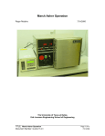
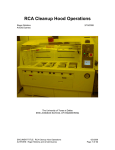
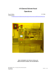
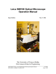
Karl Suss Contact Aligner Operation Roger Robbins 6/31/2008 Update: 10/24/2013 The University of Texas at Dallas Erik Jonsson Engineering School of Engineering ______________________________________________________________________ TITLE: Karl Suss Contact Aligner Operation Page 1 of 28 Document Number: SP2008-LI-002 10/24/2013 Author: Roger Robbins Karl Suss Contact Aligner Operation Roger Robbins 3/31/2008 Update: 10/24/2013 C:\MyDocuments\CleanRoomGeneral\Equipment\karlSussAligner\KarlSussContactAlignerOperation.doc Table of Contents Introduction ................................................................................................................. 4 Tool Description ........................................................................................................... 4 Major Components .................................................................................................. 4 Console Knobs .......................................................................................................... 4 Main Control Keyboard ............................................................................................ 7 Wafer Stage Control ................................................................................................. 8 Microscope Controls ................................................................................................ 8 Lamp Power Supply .................................................................................................. 9 Tool Operation ............................................................................................................. 9 Log Book Use ............................................................................................................ 9 Lamp Firing Procedure ........................................................................................... 10 Measuring Light Intensity at the Wafer .................................................................. 10 Loading Mask in Mask Holder .................................................................................... 12 Loading Wafer and Program Parameters ................................................................... 13 Alignment Procedures ............................................................................................... 15 Exposure .................................................................................................................... 16 Remove Wafer ........................................................................................................... 17 Remove Mask ............................................................................................................ 17 Final Notes and Considerations .................................................................................. 18 Conclusion ................................................................................................................. 18 Appendix A Small Sample Alignment ........................................................................... 19 Purpose ..................................................................................................................... 19 Discussion .................................................................................................................. 19 Alignment and Exposure Details ................................................................................ 19 Appendix B Backside Alignment ................................................................................... 22 Purpose ..................................................................................................................... 22 Concept ..................................................................................................................... 22 Backside Alignment Details ........................................................................................ 23 ______________________________________________________________________ TITLE: Karl Suss Contact Aligner Operation Page 2 of 28 Document Number: SP2008-LI-002 10/24/2013 Author: Roger Robbins Backside Alignment Verification Procedure................................................................ 25 Concept ..................................................................................................................... 25 Appendix C Quick Operation Listing .............................................................................. 27 Brief Operating Procedure ......................................................................................... 27 Load Mask .............................................................................................................. 27 Load, Align, and Expose Wafer ............................................................................... 27 Remove Mask......................................................................................................... 28 ______________________________________________________________________ TITLE: Karl Suss Contact Aligner Operation Page 3 of 28 Document Number: SP2008-LI-002 10/24/2013 Author: Roger Robbins Karl Suss Contact Aligner Operation Roger Robbins 3/31/2008 Update: 10/24/2013 C:\MyDocuments\CleanRoomGeneral\Equipment\KarlSussAligner\KarlSussContactAlignerOperation.doc Introduction The Karl Suss Contact mask aligner (MA6/BA6) has become our workhorse lithographic imaging system in the UTD Clean Room Lab. It is a versatile system allowing us to pattern a variety of substrates from 3 to 6 inch round wafers, to a large assortment of sizes and shapes of smaller substrates of various materials. It is a broadband Mercury lamp exposure system that can define structures as small as 0.7 microns. The alignment system is highly flexible, allowing rapid alignment of normal wafers, but it also has the means to align to substrates of the size category 1cm x 1cm via the use of a single alignment microscope. In addition, it has the capability to align a top side pattern to a back side pattern. With effort, the alignment accuracy can be pushed to a micron. This Operation Manual is intended to describe the operation procedures for simple cases as a starting point. Tool Description Major Components The system consists of a high pressure 1000 Watt Mercury Arc Lamp as the UV source, an optical system to present the exposure light to the wafer, a wafer stage and z-motor to bring the wafer into contact with the mask, a microscope system to measure the alignment and a mechanical mechanism to position the wafer into alignment with the mask. This is controlled by a microprocessor and appropriate buttons and knobs for the operator to perform the alignment and exposure in an efficient manner. Figure 1 shows an annotated photo of the aligner with major components identified. Console Knobs Figure 2 shows details of the main console with its adjustment knobs. This section will give brief explanations of the knobs which will then be described in the operation procedure later in the document. ______________________________________________________________________ TITLE: Karl Suss Contact Aligner Operation Page 4 of 28 Document Number: SP2008-LI-002 10/24/2013 Author: Roger Robbins Control Electronics Power Switch is a momentary engage switch used to turn on the control electronics system. It is operated by momentarily turning it to the right for ON or to the left for OFF. This is important because the electronics must be temporarily turned off in order to start the exposure lamp. Monitor Readout provides information on the machine settings and prompts for operator actions. 1000 W Exposure Lamp House Course Microscope Focus Microscope Housing Rotation Knob Microscope Fine Focus & Position Adjustment Wafer Chuck & Alignment Stage Console Power Switch Vibration Damping Air Table Monitor Readout nsole Co Main Control Console Main Control Keyboard X-Axis Align Knob (Y-Axis on opp. Side) Mask Holder Mounting Station Lamp Power Supply (Includes Lamp Intensity Meter) Microscope Separation Knobs (both sides) Vibration Damping Air Table Stage Rotation Micrometer Figure 1. Karl Suss Mask Aligner – major parts. ______________________________________________________________________ TITLE: Karl Suss Contact Aligner Operation Page 5 of 28 Document Number: SP2008-LI-002 10/24/2013 Author: Roger Robbins Control Electronics ON/OFF Switch Monitor Readout Vacuum and Pressure Gauges Split Field Selector Upper and Lower Fine Focus BSA Magnification Selector Top or Backside Illumination Selector Backside Illumination Adjustment Topside Illumination Adjustment Figure 2. Main Control Console Gauges and Regulators are used in the initial setup of the tool and are generally not important to the operator during normal lithography. Splitfield Selector allows the monitor presentation of the alignment video to be freely configured during alignment. Upper and Lower Fine Focus knobs adjust the alignment microscope focus for both photomask features and wafer features independently. Backside Alignment Magnification knob selects the magnification factor for backside alignment. Illumination Selector knob selects topside or backside illumination. Backside Illumination Adjustment adjusts the illumination intensity for backside alignment both optically and for Infrared modes. Topside Illumination Adjustment sets the illumination intensity for topside alignment. ______________________________________________________________________ TITLE: Karl Suss Contact Aligner Operation Page 6 of 28 Document Number: SP2008-LI-002 10/24/2013 Author: Roger Robbins Main Control Keyboard This membrane keyboard is the main operator interface for machine operation and is shown in Figure 3 for reference. Figure 3. Main Control Keyboard – operator control interface for operation. This keyboard is rather complicated because some of the keys have multiple operations depending on the program context. In general the keys on the left side are used frequently to start the imaging process and adjust the location of the alignment microscopes. The keys on the upper right are used to expose the wafer, change modes and parameters for special operations. The keys in the lower right corner are used during backside alignment. The keys will be described in detail in the section on operating steps. ______________________________________________________________________ TITLE: Karl Suss Contact Aligner Operation Page 7 of 28 Document Number: SP2008-LI-002 10/24/2013 Author: Roger Robbins Wafer Stage Control The wafer stage is rather complicated in detail, but the operation is simple and it is easy to manipulate. The wafer is loaded onto a separate vacuum chuck platter that just sits in a frame that pulls out for wafer loading (Figure 9). When the wafer is present the frame is pushed back into the stage mechanism and the vacuum chuck then becomes part of the mechanical stage during alignment. Wafer alignment to the photomask is accomplished by manually turning the micrometer knobs for x, y, and rotation as shown in Figure 4. Figure 4. Left side micrometer knob moves the stage in the Y-axis, while the large micrometer on the right side moves the stage in the X-axis. The small micrometer knob on the right side rotates the wafer. Microscope Controls The alignment microscope assembly is mounted on an upper frame with an xy stage in order to align the microscope to the location of the alignment markers. The microscope stage is driven around by the arrow buttons located in the mid-left side of the table top membrane keyboard. The coarse focus is set by the large knob at the top of the microscope assembly, and the assembly is rotated by a small knob on the upper right side of the scope housing as depicted in Figure 1. This stage and microscope mechanism lifts upwards via a hinge and air piston to allow access to the stage and to mask loading operations. ______________________________________________________________________ TITLE: Karl Suss Contact Aligner Operation Page 8 of 28 Document Number: SP2008-LI-002 10/24/2013 Author: Roger Robbins Lamp Power Supply The lamp that supplies the Ultra Violet (UV) exposure energy for the tool is located in a large black finned box behind the microscope assembly, (Figure 1). It contains a 1000 W high pressure mercury arc lamp bulb that is powered by a power supply box located under the table on a shelf, (Figure 5). The lamp is started by a 30,000 V pulse that initiates the arc. NOTE: The main console tool electronics must be turned off before starting the lamp to avoid damage from the startup pulse. It can be turned back on immediately after the lamp fires. There are several meters and timers located inside the lamp power supply box. We will discuss these in the following instructions. Power Supply Master Switch Numeric Readout (Start) Lamp Start Switch (momentary) (DS) Display selection (Cp, CI 1, CI 2) Constant power and Constant Intensity Mode Selection buttons Figure 5. Karl Suss Exposure Lamp power supply face showing control switches and readout. Tool Operation The following is a description of how to setup and operate the Karl Suss MA6/BA6 Contact Printer. These instructions are written in a step by step order to print a pattern onto a substrate. However there are many different procedures depending on the complexity of the job. The special printing operations will be discussed in separate sections below. Log Book Use Logbooks are provided with standard line item prompts and lines to write on. This is a mandatory step in the operation of this tool. When you sit down to use the tool, fill in the log book before you even start the tool. If you are found using a tool with no entry in the logbook you will be subject to disciplinary action. Fill in all appropriate ______________________________________________________________________ TITLE: Karl Suss Contact Aligner Operation Page 9 of 28 Document Number: SP2008-LI-002 10/24/2013 Author: Roger Robbins blanks and complete the remainder as you obtain the data and at finish. The information requested in the logbook is an important part of tool maintenance. The comment lines are to be used for your notes, and especially if you encounter a problem with the tool operation. Please make a note if anything out of the ordinary occurs during your use of the tool. Staff inspects these logbooks every day and will quickly respond to problems written in the book – otherwise it may take a while for them to be discovered – resulting in tool down time, etc. Lamp Firing Procedure This is usually the first step in preparing the tool for operation. Normally the lamp will already be on, but these are the instructions if it has not been started. Steps Turn on the lamp power supply and wait about 10 minutes to establish stability. The power supply box display will show an initialization sequence, ending with a cryptic message “rdy.” Turn off the control power using the momentary Control Electronics ON/OFF Switch on the knob panel (Figure 2). This is mandatory for protection of the control electronics from the lamp start EM interference. Momentarily Push the START switch just under the main power switch on the lamp power supply box (Figure 6). This will cause a buzzing sound as the high voltage strikes the arc in the lamp. The lamp should strike the arc in less than a second and the display will report “COLD” indicating that the lamp is not ready. At this point turn the control electronics back on with the momentary Control Electronics ON/OFF switch. Allow the lamp to warm up for about 15 minutes to achieve constant intensity before attempting a print operation. After the lamp is warm the display will report the power of the lamp in Watts. The system is set to run in constant power mode. Measuring Light Intensity at the Wafer After allowing the lamp to warm up, the next step is to determine the actual lamp light intensity at the wafer level so that you can determine the exposure time. The tool has a convenient internal intensity meter that will read out the intensity for two wavelengths, Hg G-line at 405 and Hg I-line at 365 nano meters. ______________________________________________________________________ TITLE: Karl Suss Contact Aligner Operation Page 10 of 28 Document Number: SP2008-LI-002 10/24/2013 Author: Roger Robbins Steps If there is no mask loaded yet, and the instructions in the readout say “Change Mask” then push the “Change Mask” button to reset to the “Load” message Press the LOAD button on the Main Control Keyboard (Figure 3) to initialize the electronics and mechanics. Press LAMP TEST on the upper right corner of the Main Control Keyboard. The exposure optics will slide out and the shutter will open and UV light will flood the stage. This allows the intensity meter to see light and report the intensity. To read the intensity, briefly press the DS key on the lamp power supply box under the table. The Numeric Readout will then report the light intensity of the 405 nm wavelength in the units of mw/cm2. Record this in the logbook. If you need the 365 nm wavelength intensity, briefly press the DS button again and a second sensor will report that intensity in mw/cm2. To complete the operation, press the DS button again and the lamp power will display in units of Watts. Record this value in the logbook. Do not touch the “CI” buttons under the display. Exposure Calculation Now that you have measured the lamp intensity at the wafer surface, you can determine the exposure time via the following relation: Time[sec] = Dose[mJ/cm2]/Intensity[mJ/sec.cm2] Dose represents the energy required to expose the photoresist, and Intensity represents the rate at which energy is delivered by the light. The initial dose value can be found in the manufacturer’s literature for the particular photoresist you are using. However, the exact dose required for your pattern and film thickness must be found by running an exposure test of various exposure times to determine such things as complete development, pattern fidelity, line width vs. design, and slope of the resist sidewalls. Once this has been found you can normally repeat the pattern with the determined dose, and time adjusted by the intensity variations calculated via the above relation. ______________________________________________________________________ TITLE: Karl Suss Contact Aligner Operation Page 11 of 28 Document Number: SP2008-LI-002 10/24/2013 Author: Roger Robbins Loading Mask in Mask Holder The first step in running an exposure is to load your mask into the mask holder. This is accomplished by removing the mask holder from the tool and setting it upside down on the mask holder stage to the left of the stage as depicted in Figure 7. Normally the mask holder is in this position when you approach the machine, because the last thing an operator does, is remove his mask. Note that there is a vacuum channel to affix the mask to the holder. The mask is placed over this vacuum groove against the post on the left side and Figure 7. 4 in Mask holder upside against the upper guide with the orange Si rubber down on the mask loading dock bumper. When the mask is aligned on the vacuum grooves, turn on the vacuum to hold it down. This is accomplished by pushing the “ENTER” key in response to the display instructions as seen in Figure 8. Finally, press down on the spring on the bottom rubber bumper assembly to unlatch it and allow it to snap onto the mask edge as a safety latch mechanism. Now you can pick up the mask holder, Figure 8. CHANGE MASK display turn it right side up and insert it into the dovetail with vacuum toggle note. grooves at the top of the alignment assembly and gently push it all the way in [NEVER FORCE THE MASK HOLDER INTO THE GROOVES]. It is then latched into alignment by pushing the “CHANGE MASK” button on the upper right region of the console keyboard. [ALSO – NEVER stack the mask or wafer holders on top of each other. Any “dings on the vacuum clamp surface will destroy the resolution of the tool. (Microscopic sized dings or particles are all it takes to destroy the resolution)]. ______________________________________________________________________ TITLE: Karl Suss Contact Aligner Operation Page 12 of 28 Document Number: SP2008-LI-002 10/24/2013 Author: Roger Robbins Loading Wafer and Program Parameters This is the beginning of the alignment and exposure process. Note that the display on the main console panel gives instructions for what it thinks you want to do next, and then requires conformation that you have done it. In general, if the procedure requires confirmation, the appropriate button will light up with a flashing green led. The next step will then light up the proper button with a flashing green light. Steps Figure 9. Wafer loading: Note that the wafer holder tray must be pulled all the way out to start. Push the “LOAD” button – to start the process Pull wafer holder tray all the way out Place the wafer on the vacuum chuck and bank it against the 3 tiny posts at the flat and left edge Hit “ENTER” as a response to the prompt Push the tray all the way in Hit “ENTER” again. The system will bank the wafer against the mask to make the wafer parallel to the mask, and then it will drop the wafer some distance below the mask (separation distance), so the wafer can be moved into alignment with the mask pattern. At this point, the alignment microscopes will tilt down over the mask and wafer to enable the alignment operation. WATCH YOUR HEAD AND HANDS – don’t get them squeezed to death under the descending microscope! The controller will then display a window, (Figure 10) with instructions and an opportunity to change parameters. Figure 10. Set Exposure time. Press “EDIT” and the exposure time will appear in the upper right region of the readout and you can adjust the time by pressing on either the up or down arrows in the mid left region of the membrane keyboard. When you are finished, press “ENTER” and the program will proceed. ______________________________________________________________________ TITLE: Karl Suss Contact Aligner Operation Page 13 of 28 Document Number: SP2008-LI-002 10/24/2013 Author: Roger Robbins Set Alignment Gap (microns). Press “EDIT” and the same window as above will again appear. To set the next parameter press one of the horizontal arrows and watch the parameter assignment in the upper right of the window. When Alignment Gap appears, again press the up or down arrows to change the value. This step is usually executed if a wider gap is required to overcome separation problems such as edge beads. Complete the change by pressing “ENTER.” NOTE: The mode of operation (displayed in the upper left corner of the above window) is set in a similar manner as the parameters except this must be done just after hitting the “LOAD” button to start operations. The mode is set by repeatedly pressing the “SELECT PROGRAM” button on the membrane keyboard until the desired program name appears in the window. The modes of operation are as follows: o Soft Contact – moderate contact pressure set by pneumatic pressure in a set of compression pistons pushing up on the wafer holder. o Hard Contact – high contact pressure via added N2 Pressure behind the wafer. o Low Vacuum – moderate “squeezing” force of atmosphere outside the mask and on the back side of the wafer holder. o Vacuum – Nearly full atmospheric pressure “squeezing” on the mask – wafer sandwich from the outside with a full vacuum inside. This is the highest resolution mode of the tool, but it can be hard on the mask lifetime. o Proximity – prints an image with the mask in close proximity to the wafer, but not actually touching. This saves ware and tear on the mask, but the transferred images are generally not as highresolution as those that actual contact produces. Note that only the 3’ wafer and 6” wafer mask/chuck sets can accomplish this mode. ______________________________________________________________________ TITLE: Karl Suss Contact Aligner Operation Page 14 of 28 Document Number: SP2008-LI-002 10/24/2013 Author: Roger Robbins Alignment Procedures If you have a multiple layered design, you will need to align the next level to markers on the previous level. Alignment procedures are conceptually rather simple: align the wafer features to the corresponding features on the mask, clamp the wafer to the mask and expose the image. Additional complexity comes because of the many different configurations of substrates used by investigators – principally non-round and too-small substrates. The printer has clever procedures to adapt to non-standard substrates, but these can be rather complicated, so they are relegated to the alignment appendices. The current discussion will describe a normal wafer alignment procedure. Steps After the wafer has been loaded, banked against the mask, and then backed off to the alignment gap distance, the system expects the operator to align the wafer to the mask prior to exposure. To do this, the alignment microscopes have to be positioned over the alignment marks on the mask, and then the wafer has to be moved under the mask so that the wafer alignment features line up with the mask marks. The wafer stage moves the wafer and the now stationary microscopes watch for the alignment features to appear. Set the alignment microscopes to low magnification to aid in the search for the mask alignment features. This is done by rotating the objective lenses by hand until the red-band lens is aligned with the optics. Turn the coarse focus knob on top of the optics column until the images come into approximate focus. Note the image on the monitor screen. (Figure 1) Set the position of each microscope to the spacing desired using the separation knobs. (Figure 1) Scan the microscope set across the mask looking for the alignment markers on the mask using the arrow keys on the membrane keyboard. Find the markers in one microscope. Set the fine focus by pressing the “TOP BOTTOM” button at the lower right region of the membrane keyboard until the green light comes on, signifying the optics should be fine adjusted to focus on the mask level. Then adjust the left and right fine focus knobs marked “TOP SUBSTRATE” at the lower left side of the main control console for both microscopes (left and right). Adjust the microscope lens separation until both microscopes show alignment features on the mask. o Quite probably, you will have to rotate the microscope stage with the knob on top of the microscope assembly in order to have the markers on the mask appear in both microscopes. (microscope housing rotation knob visible in Figure 1 at the top of the assembly) ______________________________________________________________________ TITLE: Karl Suss Contact Aligner Operation Page 15 of 28 Document Number: SP2008-LI-002 10/24/2013 Author: Roger Robbins Move the wafer stage with the X and Y translation micrometers on the sides of the lower alignment housing so that the images on the wafer can be seen through the mask. o If the focus is too far out to see these images, you must set the wafer focus fine adjust position. Press the “TOP BOTTOM” button at the lower right region of the membrane keyboard until the green light goes out, signifying the optics should be fine adjusted to focus on the wafer, at the gapdistance below the chrome mask plane. Then adjust the lower set of fine focus knobs labeled “”BOTTOM SUBSTRATE” at the lower left region of the main control console knob panel until the wafer features come into sharp focus on the image monitor. Note that the upper knob on the left side group of knobs, labeled “SPLITFIELD” selects “Left Objective” “Right Objective or “Splitfield” for the monitor to display. Pressing the “TOP BOTTOM” button will now toggle between sharp images of the mask feature plane and the wafer feature plane. Rotate the wafer stage with the small micrometer at the front right side of the alignment stage assembly to achieve rotational alignment between the mask and wafer. Once you have achieved alignment at low magnification, the usual procedure is to switch to higher magnification and repeat the alignment steps to achieve closer alignment. The next step is to quickly test the pattern shift to determine if the exact alignment position remains valid after wafer-mask contact. This is done by pressing the “ALIGN CONT/EXP” button in the upper left region of the membrane keyboard. o If the pattern overlay is out of alignment, try again or call Clean Room staff o If you are happy with the contact overlay alignment, continue. Exposure The next step is to press the “EXPOSE” button to expose the resist with the UV light. Note that the alignment microscope must move up out of the way of the exposure lens assembly that will move forward to expose the wafer. After the allotted exposure time has expired, the system will automatically drop the wafer away from the mask and report “PULL SLIDE AND REMOVE EXPOSED WAFER.” ______________________________________________________________________ TITLE: Karl Suss Contact Aligner Operation Page 16 of 28 Document Number: SP2008-LI-002 10/24/2013 Author: Roger Robbins Also note that the alignment microscopes drop back down after the exposure optics have been pulled out of the way after exposure – Watch Out. Remove Wafer Pull the wafer carrier forward Remove wafer. Press “ENTER” The system window reports “LOAD WAFER” for the next cycle. Remove Mask If this is the last exposure for this mask, please remove your mask. Steps Press the “CHANGE MASK” button in the upper right region of the membrane keyboard. This will raise the microscopes to allow access to the mask carrier and release the mask carrier latch so it can be pulled out of the dovetail grooves. Remove the mask carrier and place it upside down on the mask change stage to the left of the tool. The console readout will have a sign saying “PRESS ENTER TO TOGGLE MASK VACUUM.” When the mask carrier is safely sitting upside down on the mask exchange stage, press “ENTER” to release the vacuum. Pull back on the bottom rubber bumper slide until it latches away from the mask. Remove the mask and store it in a mask box in a known safe place. This condition is the normal idle condition, waiting for the next user. ______________________________________________________________________ TITLE: Karl Suss Contact Aligner Operation Page 17 of 28 Document Number: SP2008-LI-002 10/24/2013 Author: Roger Robbins Final Notes and Considerations In general, achieving a good pattern through the lithography step involves a number of parameters that must be optimized simultaneously in order to achieve good fidelity in the final image. Among these many parameters are exposure dose, resist type and thickness, develop time, primer, geometry size, substrate material, substrate reflectivity, mask quality, particles, contact quality in the printer, room humidity, etc. Semiconductor production companies spend a large amount of time and effort optimizing these parameters down to the smallest detail before they commit a process to production. Note that the mask and wafer must be free of big particles before spec resolution can be achieved. The mask vacuum rings and the wafer vacuum rings contact surfaces must also be completely free of big particles (over 1 – 2 microns in height) in order to achieve complete contact and thus resolution uniformity over the wafer. An edge bead of several microns height can reduce resolution because it prevents close contact between the mask and the wafer. o We have a set of edge bead removal masks for regular sized round wafers that expose about 2 millimeters of the extreme edge of the photoresist (that contains the edge bead). The ensuing develop process removes the edge bead so that proper contact can be achieved in the subsequent patterning step. Note that the dose required to resolve small features is larger than that required for larger geometries. The dose also depends on the resist thickness by about a 2x spread. Please note the resist manufacturer’s dose curves and the resist thickness so you can adjust the dose as required. Don’t forget to write in the log book before you use the tool and fill in detail logbook data during or at the end of you use – remember this is a mandatory rule with disciplinary consequences. Conclusion This manual has described the general operating procedures for exposing and aligning a wafer in the Karl Suss contact printer. This tool is quite versatile and has more capabilities than have been described so far in this document. If you have a special printing requirement, please discuss it with the lithography staff. ______________________________________________________________________ TITLE: Karl Suss Contact Aligner Operation Page 18 of 28 Document Number: SP2008-LI-002 10/24/2013 Author: Roger Robbins Appendix A Small Sample Alignment Alignment for a small sample Purpose This Appendix documents instructions on how to manage the alignment and exposure of “small samples” much smaller than the wafer size for the wafer chuck. Discussion Alignment and exposure of small samples deviates from the normal full sized wafer procedure because the small sample cannot cover all the vacuum chucking groves and thus causes a vacuum failure. However the Karl Suss engineers have allowed for this condition by providing an option to ignore the vacuum fault. This however eliminates the vacuum contact and proximity modes of exposure. Nevertheless, for first level exposure, the procedure is similar to the full wafer procedure except that the operator has to opt to accept the vacuum fault condition. For the second and later exposures which require alignment, the procedure deviates again since the alignment microscopes cannot both see the wafer at the same time because of the limitation of the objective separation distance – (minimum separation distance is about 4.3 cm). Again the designers have created a procedural flow which allows each marker to be viewed individually by storing the locations of each marker and having the microscopes skip back and forth between the markers as the alignment is adjusted. Details of this operation are given in the next section. Alignment and Exposure Details This description starts from the normal idle configuration where the Karl Suss MA/BA 6 contact printer is waiting for a mask to be loaded. In this case we will install the 5 inch mask holder and the 4 in wafer chuck, anticipating using a 4 in. dia. wafer. 1. Load a 5” photomask onto the mask holder a. If the wrong mask holder and wafer chuck is present, change it to the 5 in set. b. Press “Enter” to apply clamping vacuum to the mask once it is correctly aligned on the mask holder. c. Load the mask holder into the exposure frame. d. Press “Mask Change” to latch the mask holder onto the frame. 2. Press the “Load” key to initialize the system for exposure. ______________________________________________________________________ TITLE: Karl Suss Contact Aligner Operation Page 19 of 28 Document Number: SP2008-LI-002 10/24/2013 Author: Roger Robbins 3. Place your small sample onto the wafer chuck right in the middle of it - over the vacuum port hole. a. If you require a sample be offset from the middle of the chuck to match the mask pattern, you must place an equal thickness dummy sample diametrically on the other side of the center vacuum port at the same distance away from it to enable the system to set the wafer chuck parallel to the mask. Otherwise the wafer will end up nonparallel to the mask and the image will not develop properly. 4. Press “Load” and push the wafer platen into the exposure frame. a. Press “Enter” and the wafer chuck will attempt to bank the sample against the mask but will fail with an error statement “Vacuum Failure”. b. Press “Enter” to overcome the error and the system will continue the process of banking the sample against the mask and separating it for alignment. 5. If this is the first level and requires no alignment then press “Expose” and complete the process at this point by removing the sample and the mask and logging out of the log book. 6. If you require alignment, then from this point follow the procedure below: a. Move the Top Side Alignment (TSA) microscopes with the arrow keys over the sample and adjust the focus on a feature. If the feature is far out of focus, use the Coarse Focus knob at the top of the microscope assembly to obtain reasonable focus. Fine focus is achieved with the upper left console Focus knobs. (Make sure the “Top” button green light is lit.) b. If your sample is too small for both microscopes to see the sample at the same time you will have to follow the sequential alignment procedure detailed below. i. Locate the alignment mark on the mask with the left microscope using the arrow keys. ii. Press “Set Reference” on the keyboard when you locate the mark. iii. Then “Arrow” the alignment microscopes to the left until the right microscope is over the next alignment mark. iv. Move the substrate with the micrometer knobs until the wafer marks line up with the corresponding mask mark. v. Press “Scan” on the lower right console to whisk the alignment microscopes back to the first position where the left objective was over the left alignment mark. vi. Adjust the substrate stage rotation until the error is ½ of its original error. vii. Press “Scan” to move back to the other marker. ______________________________________________________________________ TITLE: Karl Suss Contact Aligner Operation Page 20 of 28 Document Number: SP2008-LI-002 10/24/2013 Author: Roger Robbins viii. Adjust the x and y position of the substrate to minimize the error. ix. Repeat this back and forth cycle until the mask and substrate are accurately aligned. x. Press “Expose” to complete the cycle. 7. At the conclusion of the expose cycle the wafer stage will drop and you can pull the drawer out and remove your sample by pushing the “Enter” button. 8. Complete the process by pressing “Change mask” and removing your mask. 9. Make sure that the wafer chuck is free of particles or photoresist. 10. Leave the tool in this configuration for the next user. ______________________________________________________________________ TITLE: Karl Suss Contact Aligner Operation Page 21 of 28 Document Number: SP2008-LI-002 10/24/2013 Author: Roger Robbins Appendix B Backside Alignment Purpose This appendix is written to simplify and clarify the instructions on how to achieve alignment between a pattern on the front side of a substrate and a new pattern on the back side using the Karl Suss contact printer in the UTD Clean Room Labs. Concept The Karl Suss printer has two sets of alignment microscopes. The top side microscopes are the normal alignment tools for stacking layers on one side of the wafer. The backside alignment feature on this tool uses two microscopes on the bottom of the wafer which look up through cutouts in the wafer platen. The backside alignment concept uses the lower microscopes to capture into memory an image of the mask markers from the bottom as the reference, and without moving the microscopes allows the user to load a wafer upside down and locate the markers on the “front” side of the wafer using the wafer stage to position the wafer markers over the saved image of the mask reference marks. This means that the newly printed image on the backside will overlay with the original image on the other (front) side of the wafer. The alignment concept follows the following protocol: 1) Load the mask with the backside pattern. 2) Click the F1 button and arrow up to find the instruction: “Turn single BSA adjustment on.” Press “Enter” to execute the instruction. 3) Load the “empty” wafer platen with backside alignment cutouts and press “Enter” to cancel “No Vacuum” error. 4) Locate the global alignment markers on the photomask with the backside microscopes and position the markers in the center of each of the split screens. NOTE: Alignment markers must be located by design to appear inside the “see through window” holes in the 6” wafer chuck. 5) Click on the console button “Grab” to save this image on the screen. 6) Unload the “empty” wafer stage. 7) Then load the wafer on the platen with the cutouts. Orient the wafer with the previously patterned side down. 8) Adjust the location of the wafer with the wafer stage micrometers until the global alignment markers on the “top” side of the wafer (which is now facing down) overlay the stored image. ______________________________________________________________________ TITLE: Karl Suss Contact Aligner Operation Page 22 of 28 Document Number: SP2008-LI-002 10/24/2013 Author: Roger Robbins 9) Test clamp the wafer to the mask and then compensate for any image shift. 10) Expose the back side of the wafer (now facing up). 11) Develop the wafer and check the alignment with the Karl Suss printer using the technique outlined in the “Check Alignment Section.” Backside Alignment Details This section gives details of the above outline, starting from the common idle configuration where the Karl Suss contact printer is waiting for a mask to be loaded. 1. Remove the safety latches from the 5 in mask holder. 2. Load a 5” photomask intended for the back side wafer pattern onto the 5 in mask holder a. Press “Enter” to apply vacuum. b. Load the mask holder onto the exposure frame. c. Press “Mask Change” to latch the mask holder onto the frame. 3. Press the “F1” key a. Press the up arrow key repeatedly until the caption “Turn single BSA adjustment on” appears. b. Press “Enter” to actuate the command. This tells the machine that you are attempting backside alignment. If you forget this, the software will not let you do backside alignment. 4. Press the “Load” key to initialize the system for exposure. 5. In the present configuration of the tool you must load the 6 in wafer chuck onto the substrate slide frame; because it is the only wafer chuck that has the back side alignment viewing slots. 6. Push the wafer slide into the exposure housing and press “Enter” to bank the empty wafer chuck against the mask and establish separation for alignment. 7. Locate the mask markers with the backside alignment microscopes. a. Press the “BSA Microscope” key to actuate control of the backside microscopes. b. Rotate the illumination selector knob on the vertical console to “BSA” from its normal “TSA” position c. Turn up the illumination knobs (also on the vertical console just to the lower left of the illumination select knob) for both backside microscopes so the image field lights up on the monitor. d. Movement: i. The backside alignment microscopes can be moved independently or simultaneously by pressing the “Left” or ______________________________________________________________________ TITLE: Karl Suss Contact Aligner Operation Page 23 of 28 Document Number: SP2008-LI-002 10/24/2013 Author: Roger Robbins “Right” or “Both” buttons in the lower right section of the lower console and then pressing the appropriate arrow keys. ii. Focus is achieved by adjusting the upper focus knobs on the left side of the upper console. The top left knob on the upper console allows selecting split screen or individual microscope fields. e. When the global alignment markers are located, position them in the center of each of the split screen fields. 8. Capture the image by pressing the “Grab Image” button in the lower right of the lower console. a. The microscope control is then automatically switched to the lower set of fine focus knobs on the upper console in preparation for focusing on the wafer. 9. Unload the empty wafer stage. 10. Load your wafer with the previous pattern containing the global alignment markers facing down and the newly coated backside up. 11. Without moving the backside microscopes, focus the backside microscopes on the wafer using the lower fine focus knobs on the left side of the vertical console. 12. Using the wafer stage micrometers (X, Y, Rotate), move the wafer until the wafer alignment markers line up with the stored image on the screen. 13. When alignment is achieved, expose the wafer. 14. Remove the wafer for develop. 15. Press the F1 key and arrow up to find the caption: “Turn single BSA adjustment off.” Pressing “Enter” returns the system to the normal top side alignment configuration for the next user. 16. Press “Change Mask” and remove your mask. a. Toggle the “Enter” key to change the state of the mask clamping vacuum from “ON” to “OFF” to release the mask. 17. Leave the tool in this state for the next user. 18. Log out of the logbook. ______________________________________________________________________ TITLE: Karl Suss Contact Aligner Operation Page 24 of 28 Document Number: SP2008-LI-002 10/24/2013 Author: Roger Robbins Backside Alignment Verification Procedure This paper describes a contrived procedure for checking the backside alignment to a reference on the front side after both the top-side and back-side patterns have been imaged. As far as I can tell, there is no routine on the tool that allows this alignment check in a pre-programmed standard tool procedure. The procedure that I came up with is a bit cumbersome, but allows a confidence check to a “loose” tolerance. Concept The Karl Suss contact printer has two sets of alignment microscopes (independent front and back side microscopes) so that a pattern can be printed on the back side of a substrate and be aligned to the pattern on the front side. The alignment check concept requires that the top side alignment marks and the bottom side alignment marks be at the same relative coordinate location on the front and back side masks and have some aspect of symmetry that can be compared as a point location by both the front side microscopes and the back side microscopes. Detailed Verification Procedure Detailed procedure follows: 1. Load the top-side pattern mask into the tool. 2. By moving the top-side alignment microscopes, find the left and right side alignment markers and place them in the center of the LCD screen panels. 3. Then stick a removable sticky tape over the symmetry point on both sides and ink a dot at the symmetry point that is to align with the symmetry point on the backside wafer marker later. Now the top side microscopes are aligned to the mask - do not move the topside microscopes any more. [Make a “handle” on the sticky tape by folding a portion over so the sticky side sticks to the tape sticky side in order to make a slick handle for tape removal.] 4. Press “F1” and then press the left or right arrow key on the lower keyboard to sift through the choices until “Turn single BSA align on” shows up. Press “Enter” to activate. If you forget this, the software will not allow you to perform backside alignment. 5. Place the empty 6” wafer carrier (with alignment holes) on the tray and “load” the empty wafer carrier into position under the mask for alignment. (Press “Enter” to cancel “No Vacuum” error). ______________________________________________________________________ TITLE: Karl Suss Contact Aligner Operation Page 25 of 28 Document Number: SP2008-LI-002 10/24/2013 Author: Roger Robbins 6. Switch to the backside alignment microscopes: a) Switch to the BSA illumination using the BSA rotary switch on the upper console, b) press the “BSA” button on the lower console. 7. Drive the BSA microscopes around (together or independently) to center the mask alignment mark symmetry points over the alignment “Dots” on the sticky tapes placed on the LCD screen earlier. *Press the “X”, “Y”, or “Both” in the lower right section of the lower console to enable the arrow keys to move the back side microscopes.] 8. Now both the top and backside microscopes are set in alignment with the same mask feature. 9. Without moving the backside microscopes any more, unload the (empty) wafer holder. 10. Load your wafer on the wafer holder with the top side pattern (identical to mask pattern) facing up. 11. Now using the top side microscope image on the screen, move the wafer stage (x, y, & rot) until you find the top side markers and align the wafer pattern to the mask. 12. Then switch to the backside microscope view. The symmetry points viewed in the back-side microscopes should overlay the dots, symmetrically. [The backside microscopes have a different magnification than the top side microscopes – thus regard the dot as the symmetry alignment reference – rather than the size of the pattern.] 13. If the above alignment is achieved, the front and back-side patterns should overlay to some level of accuracy depending on the skill of the operator in placing the dot and sticky tape accurately, and then centering the wafer stage symmetrically with respect to the tape dots. ______________________________________________________________________ TITLE: Karl Suss Contact Aligner Operation Page 26 of 28 Document Number: SP2008-LI-002 10/24/2013 Author: Roger Robbins Appendix C Quick Operation Listing This quick step by step listing of the procedure for printing a pattern on a nice round wafer is intended as a reminder of the procedure for those already trained on the system but who have not used it in a while. This procedure starts in the standard ready configuration awaiting a mask. Brief Operating Procedure Load Mask 1. Place photomask on Mask holder with the Chrome side up and the top of the pattern away from you. 2. Press “Enter” on the lower console to apply vacuum clamping to the mask. 3. Release the latch on the rubber safety latch to hold mask in case the vacuum fails. 4. Slide mask holder into the Dove Tail grooves on the exposure frame. 5. Press “Change Mask” key on the console to clamp mask holder onto the exposure frame. Load, Align, and Expose Wafer 1. Pull the wafer chuck slide out of the exposure frame. 2. Place resist coated wafer on the wafer chuck with the wafer flat toward you and align it to the 3 tiny pegs in the chuck. 3. Press “Load” and follow the instructions in the readout on the console panel. 4. Push the wafer chuck drawer back into the exposure frame and press “Enter” a. The tool will bank the wafer against the mask to establish a parallel plane for the wafer. b. The wafer chuck will then separate from the mask by a small amount so you can adjust its position to line up fiducials on the wafer to those on the mask for overlay. 5. Move the wafer via the large micrometer knobs on the exposure housing to align the wafer markers with the mask markers for pattern overlay. (If necessary) 6. When the alignment is complete press the “Exposure” button to expose the wafer. 7. When the wafer chuck is disengaged from contact with the mask, the console readout will suggest that you pull the drawer out and take your exposed sample away for development. Push the drawer back into the housing before leaving. ______________________________________________________________________ TITLE: Karl Suss Contact Aligner Operation Page 27 of 28 Document Number: SP2008-LI-002 10/24/2013 Author: Roger Robbins Remove Mask 1. Press “Change Mask” and pull the mask holder out of the dove tail groves and set it upside down on the mask holder shelf to the left of the system. 2. Pull the safety latch away from the mask until it latches. 3. Press “Enter” to remove the clamping vacuum 4. Remove your mask 5. Log out of the logbook and go develop your sample. ______________________________________________________________________ TITLE: Karl Suss Contact Aligner Operation Page 28 of 28 Document Number: SP2008-LI-002 10/24/2013 Author: Roger Robbins