1
US006713678B2
(12)
(54)
United States Patent
(10) Patent N0.:
Masuda et al.
(45) Date of Patent:
Mar. 30, 2004
CABLE MANAGEMENT SYSTEM FOR
6,229,584 B1 *
ELECTRONIC DEVICES SUCH AS FLAT
PANEL MONITORS
6,307,530 B1 * 10/2001 Cho ......... ..
6,392,873 B1 * 5/2002 Honda ...................... .. 361/681
(75) Inventors: Kuni Masuda, Cupertino, CA (US);
J09 Miseli, San Bruno, CA (Us)
_
_
Notice"
'
5/2001 Chuo et a1. ................. .. 349/58
OTHER PUBLICATIONS
Quick Start user’s manual for LCD1550X.P65, Oct. 10,
2001, pp. 4 to 6*
(73) Asslgnee: Sun Mlcrosystems’ Inc" Palo Alto’ CA
(Us)
(*)
US 6,713,678 B2
Subject to any disclaimer the term of this
patent is extended or adiusted under 35
U.S.C. 154(1)) by 0 days.
(21) App1_ No; 10/096,349
Quick Start user’s manual for LCD2110usersmanual, Apr.
23, 2001, pp. 4 and 6.*
“The Titan Series for LCD Monitors,” [internet] httpj/
WWW.icWusa.com/titan.html, pp. 1—4, Printed Mar. 3, 2002.
* Cited by examiner
Primary Examiner—Dean A. Reichard
_
Assistant Examiner—Jinhee Lee
(22) F1169:
Mar- 11’ 2002
(74) Attorney, Agent, or Firm—O’Melveny & Myers LLP
(65)
Prior Publication Data
(57)
ABSTRACT
(51)
Us 2003/0168238 A1 Sep' 11’ 2003
Int. Cl.7 ................................................ .. H01B 7/00
A system for managing cables is disclosed herein. A pre
ferred aspect of the system comprises a ?at panel monitor
(52)
us CL _______________ __ 174/72 A; 174/135; 174/138 E;
haying a front surface, a rear surface, a left‘ side surface and
(58)
361/683
Field of Search ............................. .. 174/72 A, 135,
174/138 E. 361/683 680 681 11
a r1ghts1de surface. The system also comprises a plurality of
downwardly facing Cable portals Coupled to the rear Surface
’
(56)
’
’
’
References Cited
of the ?at panel momtor and a stand coupled to the rear
surface of the ?at panel monitor, Wherein the ?at panel
monitor is forWardly rotatable on a horizontal axis; and a
plurality of releasably connectable retaining member are
US. PATENT DOCUMENTS
5,229,757 A
5,812,368 A
*
*
coupled to the rear surface of the ?at panel monitor.
7/1993 Takamiya et a1. ......... .. 345/168
9/1998
21 Claims, 3 Drawing Sheets
Chen et a1. ............... .. 361/681
HE
22
_E
22
22
22
22
22
22
,@@r;\-@-@;@/
_
i
I
U.S. Patent
Mar. 30, 2004
Sheet 1 of3
“8
FIG. 7
US 6,713,678 B2
NN
U.S. Patent
Mar. 30, 2004
Sheet 2 of3
;
20
F/G. 2
FIG. 5
US 6,713,678 B2
U.S. Patent
Mar. 30, 2004
Sheet 3 of3
US 6,713,678 B2
US 6,713,678 B2
1
2
CABLE MANAGEMENT SYSTEM FOR
ELECTRONIC DEVICES SUCH AS FLAT
PANEL MONITORS
The disclosed method comprises providing a monitor
head assembly that may be disposed on a support member
connected by a rotatable joining member. The rear of the ?at
panel monitor is situated facing the user and the bottom of
the display head is rotated toWards the user While the top of
BACKGROUND
the top is rotated aWay from the user. Next, the user accesses
the doWnWardly facing cable portals located on the bottom
1. Field of the System
The present invention relates to electronic devices With
surface of the upper planar surface on the rear of the ?at
panel monitor. Next, cables are coupled betWeen the doWn
portals for attaching various other electronic devices using
Wardly facing cable portals and the releasably connectable
cables. More speci?cally, the present system relates to a
retaining members located on the loWer planar surface of the
rear of the ?at panel monitor assembly. The cables are placed
in a horiZontal direction along the releasable retaining
system for cable management for liquid crystal display
(LCD) or other ?at panel monitors, or other electronic
devices.
2. Background of the System
member or members such that the cables are arranged in an
15
Various electronic devices such as computer monitors
orderly fashion.
BRIEF DESCRIPTION OF THE DRAWINGS
including both ?at panel and cathode ray tube (CRT)
displays, video players and recorders, televisions and the
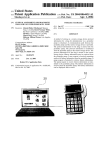
FIG. 1 shoWs the cable management system according to
like require cables to connect these devices to other com
the present system.
ponents in the particular system. For instance, a typical
FIG. 2 is a top vieW of the cable management system
computer has a monitor, a hard drive storage system, a
keyboard, mouse, etc. A monitor itself can have multiple
according to the present system.
cables for connection to the computer hard drive, speakers,
management system of the present system.
a video player, a video camera, digital video input, etc. It
may even include serial port hubs for easy interconnection
of interface devices, such as keyboards or mice.
FIG. 3 is a bottom vieW of one portion of the cable
25
A computer monitor With multiple cable portals and
multiple cables dangling can be unsightly and even danger
DETAILED DESCRIPTION
Those of ordinary skill in the art Will realiZe that the
ous. Dangling cables can interfere With usability. The cables
may also be dangerous because if multiple cables are
hanging to the ?oor in a disorderly fashion they may cause
folloWing description of the present system is illustrative
a person to trip and fall over them or cause damage to
equipment by being ensnared. In addition, the cable portals
are usually on the back of a computer monitor such that
When a cable is attached the cable sticks straight out from the
back of the monitor. This can make it dif?cult to place a
FIG. 4 is a side vieW of the cable management system of
the present system.
35
monitor close to a Wall or in a console or When mounting
several adjacent computers, etc.
only and not in any Way limiting. Other embodiments Will
readily suggest themselves to such skilled persons having
the bene?t of this disclosure.
Similar designations used herein are intended to designate
substantially similar matter.
FIG. 1 shoWing a cable management system 10 con?g
ured for use the teachings of this disclosure. The embodi
ment depicted in FIG. 1 is deployed on a ?at panel monitor,
though this is but one illustrative eXample of a disclosed
BRIEF DESCRIPTION
system. As Will be appreciated by those of ordinary skill in
A system for managing cables is disclosed herein. A
preferred aspect of the system comprises a ?at panel monitor
the art having the bene?t of this disclosure, the disclosed
system may be used on any variety of electronic devices
requiring cable connections to other electronic devices. FIG.
having a front surface, a rear surface, a left side surface and
a right side surface. The system also comprises a plurality of
doWnWardly facing cable portals coupled to the rear surface
1 is shoWn as an illustrative eXample only and in no Way
45
FIG. 1 shoWs a rear vieW of a ?at panel monitor having
of the ?at panel monitor enclosure and a support member
coupled to the rear surface of the ?at panel monitor through
a rotatable joining member, Wherein the ?at panel monitor is
cable management system 10 of the disclosed system. Rear
surface 12 of the ?at panel monitor comprises an upper
planar surface 14 and a loWer planar surface 16. In one
aspect of the present system, upper planar surface 14 has a
greater front to back Width than loWer planar surface 16.
forWardly rotatable on the rotatable joining member on a
horiZontal aXis. In another aspect of the disclosed system,
the rear surface of the ?at panel monitor may be coupled to
a Wall through a Wall mounting device, the cable portals are
then accessed from beloW the device. Aplurality of releas
ably connectable retaining members are coupled to the rear
surface of the ?at panel monitor.
An aspect of the above disclosed system comprises a ?at
and thin ?at panel monitor assembly With a rear surface that
has an upper substantially planar surface and a loWer sub
limits the disclosed system.
Upper planar surface 14 of rear surface 12 of the ?at panel
monitor has a bottom surface 18. Disposed on bottom
55 surface 18 of upper planar surface 14 are a plurality of
doWnWardly facing cable portals. The plurality of doWn
Wardly facing cable portals Will be discussed in greater
detail beloW.
Disposed on loWer planar surface 16 of rear surface 12 of
the ?at panel monitor are a plurality of releasably connect
able retaining members 22. In another aspect of the dis
closed system, there may only be a single continuous
stantially planar surface perpendicular to the right side
surface and the left side surface. The upper planar surface of
the ?at panel monitor has greater depth than the loWer planar
one or a plurality of releasably connectable retaining mem
releasably connectable retaining member 22.
Releasably connectable retaining members 22 should be
formed from any resilient, semi-rigid to rigid material. For
eXample, releasably connectable retaining members 22 may
bers.
be formed from stainless steel. HoWever, releasably con
surface and the bottom of the upper planar surface has a
plurality of doWnWardly facing cable portals. Finally, the
loWer planar rear surface of the monitor assembly may have
65
US 6,713,678 B2
3
4
nectable retaining members 22 can be formed from any
number of resilient materials such as plastic or aluminum. In
addition, retaining members can be ?xed to the electronic
device, such as built in clips or they can be removable. They
can also be designed to Wrap around the cables completely
or designed more like hooks such that the cables lay on top
USB portals 20 that may or may not be included in the
disclosed invention. Also disposed on loWer planar surface
16 are a plurality of releasably connectable retaining mem
bers. As seen clearly in FIG. 4, releasably connectable
retaining members 22 may be hook shaped to hold cables
from any of the above mentioned cable portals 28 or USB
portals 20 or any other cables in proximity to the ?at panel
of the retaining members. They may have spring-type
mechanisms to alloW for closure around any cables lain
Within them. In another aspect of the disclosed system,
releasably connectable retaining member 22 may be a single
continuous member having a length substantially the same
monitor or electronic device. It can also be used for con
tainment of any other cables used Within proximity to the ?at
10
or similar to the electronic device.
Lower planar surface 16 also comprises raised portion 19.
Disposed on one side of raised portion 19 are universal serial
bus (USB) portals 20.
Also shoWn in FIG. 1 is a stand or support member 24
15
coupled to ?at panel monitor 12 head assembly by a rotat
able joining member. Support member 24 and rotatable
joining member Will be discussed in greater detail beloW.
FIG. 2 is a top vieW of cable management system 10
surface has a greater Width than rear surface 12. Also
disclosed in FIG. 2 are USB portals 20 disposed on raised 25
surface 19.
FIG. 3 shoWs bottom surface 18 of upper planar surface
14. Disposed on bottom surface 18 are cable portals 28 for
various types of cables. As knoWn to those of ordinary skill
in the art, cable portals 28 can include portals for various
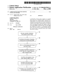
A method of cable management Will noW be disclosed. In
one aspect, a method may comprise the folloWing steps. It is
equipment. For this embodiment, the method Will be illus
trated using the ?at panel monitor as disclosed above, but the
folloWing method may be performed using structure other
than that illustrated here, or in a different order, Without
departing from the scope of this disclosure. First, rear
surface of ?at panel monitor 12 is situated facing the user.
35
Rear surface of ?at panel monitor 12 is rotated on rotatable
joining member 30 on a substantially horiZontal axis so that
the bottom half of the ?at panel monitor is rotated toWards
the user and the top half of the monitor is rotated aWay from
the user such that cable portals 28 on the bottom surface 18
of upper planar surface 14 are facing the user. Once cable
portals 28 are facing the user, the user can insert cables into
?at panel monitor. Thus, in the present example cable portals
28 are located slightly beloW the center of rear surface 12
and can be easily accessed by the user of the electronic
cable portals 28.
device, in this case, the ?at panel monitor, When the elec
tronic device is rotated on rotating joining member along a
substantially horiZontal axis. The electronic device is rotated
In another aspect of the disclosed system, the ?at panel
monitor is coupled to a Wall or other solid surface. In this
45
aspect, cable portals 28 are accessed from beloW the ?at
panel monitor.
Next the cables are placed into releasable retaining mem
bers 22 so that the cables are situated along a substantially
In another aspect of the disclosed system, the ?at panel
monitor may be mounted to a Wall or other solid surface. In
horiZontal axis and held in place by releasable retaining
this case, cable portals 28 are disposed in such a Way that
they are doWnWardly facing When the display 12 is in use.
Upper planar surface 14 is disposed on approximately the
upper tWo-thirds of rear surface 12 of the ?at panel monitor.
Thus, in the present example cable portals 28 are located
55
members 22. Next, rear surface of ?at panel monitor 12 is
rotated so that the bottom of the ?at panel monitor is rotated
aWay from the user and the top of the ?at panel monitor is
rotated toWards the user. Rear surface of ?at panel monitor
12 is rotated in this manner until it is in a substantially
vertical position. Thus, the cable management system 10
noW contains all of the cables inserted into cable portals 28
?at panel monitor, from beloW the electronic device because
and organiZes the cables in a neat and efficient manner
of its location on a Wall or other solid surface.
Within the releasable retaining members 22 such that all
FIG. 4 is a side vieW of the cable management system 10
of the present system. For illustrative purposes, cable man
agement system 10 is shoWn as used on a ?at panel monitor.
Flat panel monitor has a front surface 26 and a rear surface
12. Disposed on rear surface 12 is an upper planar surface
14. As discussed previously, upper planar surface has a
greater Width than loWer planar surface 16.
Disposed on loWer planar surface 16 is raised surface 19.
In the present example, raised surface 19 has a plurality of
solid surface.
to be understood that the folloWing acts may be accom
plished in a variety of manners using a Wide array of
types of cables. For example, cable portals 28 may be
designed to accommodate audio cables, video cables, com
slightly beloW the center of rear surface 12 and can be easily
accessed by the user of the electronic device, in this case, the
cables in place including a single continuous releasably
connectable retaining member.
other electronic device may be coupled to a Wall or other
clearly in FIG. 2 and as discussed above, upper planar
such that the bottom of the device is rotated toWards the user
While the top of the device is rotated aWay from the user.
This alloWs for easy access to cable portals 28 by the user.
hook shape, or frictional ridges to more securely hold the
Also shoWn in FIG. 4 is support member 24. Support
member 24 is coupled to the rear head assembly of ?at panel
monitor 12 though rotatable joining member 30. In another
aspect of the disclosed system, the ?at panel monitor or
comprising a ?at panel monitor With a front surface 26, rear
surface 12 and upper planar surface 14. As shoWn more
puter cables, poWer cables or any type of cable or adapter
that is needed to operate or to be coupled to the device. As
shoWn in FIGS. 1 and 3, cable portals 28 are disposed in
such a Way that they are doWnWardly facing When the
display 12 is in use. Upper planar surface 14 is disposed on
approximately the upper tWo-thirds of rear surface 12 of the
panel monitor, Which might pass across it. It is contemplated
that the retaining members 22 may comprise any shape
suitable for retaining cables in place. For example, it is
contemplated that the retaining members may include a
cables are directed toWards one or both sides of the ?at panel
monitor display in an orderly fashion.
While embodiments and applications of this system have
been shoWn and described, it Would be apparent to those
skilled in the art that many more modi?cations than men
65
tioned above are possible Without departing from the inven
tive concepts herein. The system, therefore, is not to be
restricted except in the spirit of the appended claims.
US 6,713,678 B2
6
5
11. The system according to claim 5, Wherein said releas
ably connectable retaining members comprise a single con
tinuous support member having a length substantially simi
What is claimed is:
1. A system for managing cables comprising:
an electronic device having a front display surface and a
lar to said electronic device.
rear surface having a plurality of doWnWardly facing
cable portals; and
a plurality of releasably connectable retaining members
disposed about said rear surface;
12. The system according to claim 5, Wherein said releas
ably connectable retaining members form a single continu
ous support member having a length substantially similar to
Wherein said plurality of doWnWardly facing cable portals
said electronic device.
are to be inserted by a plurality of external cables; and
10
Wherein said plurality of releasably connectable retaining
13. The system according to claim 1, Wherein said releas
ably connectable retaining members have a Wrap-around and
members have a predetermined shape for retaining and
hooked shape.
horiZontally directing said plurality of external cables.
14. The system according to claim 1, Wherein each of said
plurality of releasably connectable retaining members com
prises an angled region facing aWay from said rear surface,
said angled region forming a hook for vertically retaining
and horiZontally directing said external cables.
15. The system according to claim 1,
Wherein each of said plurality of releasably connectable
retaining members comprises a loop having tWo ends
2. The system according to claim 1,
Wherein said rear surface of said electronic device com
15
prises a right side surface, a left side surface, an upper
planar surface, and a loWer planar surface;
Wherein said upper and loWer planar surfaces are perpen
dicular to said right and left side surfaces of said
device;
connected to said rear surface; and
Wherein said upper planar surface has a greater Width than
said loWer planar surface and comprises a bottom
Wherein said loop can be used to engulf said external
cables.
surface;
Wherein said plurality of doWnWardly facing cable portals
are disposed about said bottom surface; and
25
Wherein said plurality of releasably connectable retaining
retaining members comprises a ?rst end, a second end
and an arch end;
members are disposed about said loWer planar surface.
3. The system according to claim 1, Wherein said front
display surface is coupled to a hinge providing rotation of
the monitor assembly about a horiZontal axis.
4. The system according to claim 1, Wherein said front
Wherein said ?rst and second ends are connected to said
rear surface; and
Wherein said arch end is disposed aWay from said rear
surface.
display surface comprises a ?at panel monitor assembly.
5. The system according to claim 1, Wherein said plurality
of external cables are directly coupled to said doWnWardly
facing cable portals of said electronic device.
6. The system according to claim 5, Wherein said plurality
35
of external cables are directly coupled from one of said
doWnWardly facing cable portals of said rear surface to one
of said releasably connectable retaining members of said
rear surface.
7. The system according to claim 5, Wherein said plurality
of releasably connectable retaining members comprise a
channel and Wherein said plurality of external cables are
disposed in a horiZontal direction along said channel of said
releasably connectable retaining members.
8. The system according to claim 5, Wherein said plurality
of releasably connectable retaining members comprise a
plurality of hooks permitting said plurality of external cables
to lay on top of said plurality of releasably connectable
retaining members.
9. The system according to claim 5, Wherein said plurality
of releasably connectable retaining members comprise a
spring-type mechanism for releasably alloWing for non
permanent closure around said plurality of external cables.
10. The system according to claim 5, Wherein said plu
rality of releasably connectable retaining members comprise
16. The system according to claim 1,
Wherein each of said plurality of releasably connectable
45
17. The system according to claim 16, Wherein said
arched end is angled to form a hook for vertically retaining
and horiZontally directing said external cables.
18. The system according to claim 1,
Wherein each of said plurality of releasably connectable
retaining members comprises an arched loop for Wrap
ping said external cables and an angled portion for
hooking said external cables;
Wherein said plurality of releasably connectable retaining
members comprise a stainless steel material; and
Wherein each of said plurality of retaining members is
releasably connected to said rear surface of said elec
tronic device.
19. The system according to claim 1, Wherein each of said
plurality of releasably connectable retaining members are
disposed about said rear surface in a horiZontal direction.
20. The system according to claim 19, Wherein each of
said external cables is adapted to meet up With any one of
said retaining members at any point along said rear surface.
21. The system according to claim 1, Wherein said plu
rality of releasably connectable retaining members forms a
horiZontal channel adapted to lead said external cables to
both left and right sides of said rear surface.
a Wrapping mechanism to completely Wrap around said
plurality of external cables.
*
*
*
*
*