1
Fig. 19 – GAM 110/Dual Capture Module connection cable.
Fig. 20 – GAM 110 to Dual Capture Module connection simplified scheme.
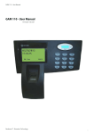
The GAM 110 is fixed to the housing 4X3 conduit box previously fixed in the wall. A conduit allows the connection between GAM 110 and the Dual Capture Module.
4.3 – GAM 110/Dual Capture Module Connection
To establish connection between GAM 110 and Dual Capture Module use the supplied cable which is present in Dual Capture Module package. Follow the steps below:
1 - Please execute the static electrical discharge procedure.
2 - Unmount the enclosure of both units.
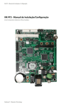
3 - Plug any side of the supplied cable to CN6 connector of GAM 110. Check the figure 21.
4 - Plug the other end of the cable to CN3 connector of Dual Capture Module. Check figures 22 & 23
NOTE: Pin number 1 of the connectors in the GAM 110 and Dual Capture Module boards are indicated by a
triangle mark.I
16