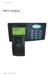
Download GAM 110 - Installation Manual
Transcript
GAM 110 - Installation Manual
GAM 110 - Installation Manual
Neokoros IT - Biometric Technology
ATTENTION! STATIC ELECTRICITY SENSITIVE DEVICE!
The GAM 110 just like any other electronic device is susceptible to irreparable
damage caused by occasional static electricity discharge in its inner board
and components. It is essential to carry out the static electricity unloading
from the body prior any installation/operation procedures. It is strongly recommended to avoid any unnecessary contact with the device components.
WARNING: damages caused by static electrical discharges are NOT covered
by the End User Warranty Certificate!
To discharge static electricity, consider the following procedures before any
operation including the GAM 110:
1 - With your computer off, make sure it is grounded keeping its power cord plugged into a 3 prong grounded outlet.
2 - Touch - for few seconds - a bare metal frame (not a painted or coated surface) of the computer case.
Turn the computer on.
3 - With the computer on, repeat the step 2. Keep your hand in contact with the computer case for few
seconds.
4 - Consider to use a static eletricity discharging wristband to perform long operations using the GAM 110
internal components. Electricity discharging wristbands are available in electronics supplies stores. Please
refer to manufactures instructions to static electricity discharging optimization.
5 - The device now is ready for assembling and connections. Avoid unnecessary contact with the device
internal components.
ATTENTION!
AVOID INAPPROPRIATE DISPOSAL OF THIS DEVICE AND ITS COMPONENTS!
This device is made using electronic components which can be harmful to
environment if not properly disposed. Please check your local rules and
regulations for the proper disposal and recycling of this device and its
components after the end of its life cycle.
ATTENTION!
DO NOT USE CAPACITORS FOR RECIRCULATION! USE ONLY DIODE!
IMPORTANT:
TO AVOID DAMAGE TO THE UNIT USE THE PROVIDED SCREWS ONLY
Additional information covering settings, device configuration and operation
can be found in the GAM 110 User Manual. Before any attempt to install and
use GAM 110, please read both documents to assure correct device
installation, configuration and operation.
The internal board connectors shown in this document figures are referring to REV1 of GAM 110.
Connectors in REV2 are in different position on the board although they keep the same functions.
All Rights Reserved © 2010 - 2014.
GAM 110 - Installation Manual
Contents - GAM 110 Installation Manual
1 - Package Components...................................................................................... 7
1.1 - Fixation Screw............................................................................................................7
1.2 - Power Supply.............................................................................................................8
1.3 - Power Injector...........................................................................................................8
1.4 - Wires..........................................................................................................................9
2 - Additional Components................................................................................... 9
2.1 - Dual Capture Module................................................................................................9
2.2 - Other Components..................................................................................................10
3 - Internal Components..................................................................................... 10
3.1 - Opening the GAM 110.............................................................................................10
4 - Fixing The GAM 110...................................................................................... 14
4.1 - Wall Fixing................................................................................................................14
4.2 - Fixing: Dual Capture Module...................................................................................15
4.3 – GAM 110/Dual Capture Module Connection..........................................................16
5 – Wiring Diagrams: Lock/Electromagnet......................................................... 18
5.1 – Lock Connection (POE or INJECTOR electric power with 48v power supply)..........18
5.2 – Lock Connection......................................................................................................20
5.3 – Electromagnet Connection (POE or INJECTOR).......................................................22
5.4 – Electromagnet Connection.....................................................................................24
6 – Setting the GAM 110.................................................................................... 26
6.1 – Connection to Electric Power Outlet/Data..............................................................26
6.2 – Identifying the Network..........................................................................................27
6.3 – NKHM (Neokoros Hardware Manager)...................................................................29
6.4 – Configuration Options (CA).....................................................................................31
Warranty Certificate..............................................................................................................35
1 - Package Components
The GAM 110 device is offered with different components according the customer specific needs. Please
check if the required items are present after opening the package. The follow section describes the standard components found in every GAM 110 device package:
1.1 - Fixation Screw
Fig.1 – Panels fixing screw
The snap in plastic fasteners (fig.2) of the front and rear device panels provides the junction to GAM 110
enclosure. The screw fastening of the panels must be properply placed at the bottom of GAM 110 in the
location shown in figure 3.
Fig.2 – Detail of snap fasteners. GAM 110 rear panel (inside).
NOTE: Although the fitting pressure between the two panels provide strength to the whole device body enclosure, is essential to use the screw to provide greater protection to internal GAM 110 components.
Fig.3 – Screw attachment
position at the bottom of
GAM 110.
1.2 - Power Supply
The electric power supply provided with the GAM 110 can be used in 110/220 outlets without any manual
voltage commutation.
NOTE: Please do not any other power supply than the model supplied with the GAM 110. The use of a non
compliant power supply can cause serious and irreparable damage to equipment also loss of the Warranty
Certificate.
Fig.4 – The provided power supply can be used in 110/220 AC outlets without manual voltage commutation.
1.3 - Power Injector
The supplied power injector allows connecting the GAM 110 to the pow er source and the network. It has
three connectors as shown in figure 5; (input to network cable, connector and electrical source).
Fig.5 – Power injector: connectors for network cable switch and power supply. The network cable is connected to GAM 110.
NOTE: The network cable must be connected to the injector in the position as indicated in the figure. It’s imperative to connect the switch correctly. Never connect the already inserted (in the injector) network cable
to any other device. The reversal of the connections can may cause irreversible damage to GAM 110, and
the network. Damages caused by incorrect connections are not covered by the Warranty Certificate.
1.4 - Wires
The colored wires (figs 6 & 7) provided with GAM 110 are used to communication thru RS-232, RS-485A,
RS-485B serial ports. The wires also are used to connect the device to sensors.
The white wires are used to external devices triggering; (locks, gates, electromagnetic locks, electromagnets and others).
The black and red wires are used to the 12V power supply when the GAM is turned on without the injector
and the correspondent 48V POE power supply.
Fig. 6 & 7 – Supplied connection wires.
NOTE: To additional information covering connections and external devices utilization, please refer to GAM
110 User Manual.
2 - Additional Components
The GAM 110 can use several additional components to fit the device to specific user needs.
2.1 - Dual Capture Module
The Dual Capture Module is an example of an optional GAM 110 additional component; (fig.8).
Fig.8 – Dual Capture Module. Optional component for use with GAM 110
The device is designed to control the flow of personnel. With the Dual Capture Module, is possible to authorize and register every people entry/exit replacing the use of the tradional pushbuton devices.
Use the same type of wire supplied with the GAM 110 to connect the Dual Capture Module. For connection
instructionsl, please refer to the GAM 110 User Manual.
The Dual Capture Module is shipped with 4 screws for its frontal panel assembling; (fig.9).
Fig.9 – Dual Capture Module front panel fixation screws.
2.2 - Other Components
Other components which can be used with GAM 110:
- pushbuttons;
- electromagnetic locks;
- opening sensors;
- card readers (proximity, bar code, etc).
3 - Internal Components
If necessary, the internal GAM 110 section, containing its board, can be easily accessed.
3.1 - Opening the GAM 110
To open the GAM 110 enclosure to access its internal components, please follow the steps below:
1 – Please make sure the equipment is not connected to the electrical power outlet. Disconnect all cables
from the GAM 110.
2 – Discharge the static electricity from the body. Touch metallic surfaces and walls for few seconds.
NOTE: Never touch the GAM 110 internal components without the static electricity discharge. This can potentially cause irreversible damages to GAM 110 board.
3 – Remove the fixation screw located at the bottom of GAM 110.
4 – Hold the GAM 110 as shown in the figure 10. Press it with the thumb where it is located in the figure.
5 – Separate the two sections of the enclosure; (figs. 11 & 12).
10
Fig.10 – Remove the screw at the bottom of the GAM 110 then use the thumb to press the enclosure as shown in the figure.
Fig. 11 - After the screw removal...
11
Fig.12 – …separate the GAM 110 panels as shown in the figure.
Inside the back external section there is a product information tag; (fig.13).
Fig.13 – External tag in the back panel of GAM 110 enclosure.
12
The figure 14 shows the GAM 110 internal board and the tag containing the unit serial number; (fig. 15).
Fig.14 - GAM 110 Internal Board where is located...
Fig.15 - ...the unit serial number tag
13
NOTE: In order to preserve the necessary unit information integrity for authorized services and support please do not remove any internal/external tags and seals from the GAM 110.
4 - Fixing The GAM 110
The recommended height for fixing the unit to the wall it is 1,5m (1500mm) from the floor to the top of the
device; (fig. 16).
Fig.16 – Recommended height for
the GAM 110 installation.
4.1 - Wall Fixing
The rear panel of GAM 110 has three holes for fastening screws/6 mm sockets.
It is possible to mount the equipment in a 4X3 conduit box of the type shown in figure 16. This type of connection is particularly useful to taking advantage of the duct connected to the box, where the cables and
other network connections can be stowed.
A 4X3 box with the GAM 110 set will require the insertion of another bolt/socket according to another hole
in the wall; (figs 17 & 18).
The equipment can also be attached to an acrylic plate. The acrylic plate, with the GAM 110 attached, can
be mounted on the wall. To perform this type of assembling, 4mm screws must be used.
Fig. 17 – The GAM 110 can be fixed in a 4X3 conduit box.
14
Fig. 18 – Mounting screws locations at the GAM 110 rear section. The unit can be attached to a 4X3 conduit box with 6mm screws/
6mm sockets. For the acrylic plate unit mounting, use 4mm screws.
NOTE: The additional screw located at the right side of the bottom panel must be used in 4X3 box wall fixation and if it will be attached to an acrylic plate).
4.2 - Fixing: Dual Capture Module
The Dual Capture Module consists of reading, identification and authorization of incoming and outgoing
personnel. When the GAM 110 is used with the Dual Capture Module, entries are recorded in the equipment. The outputs are read by the module and controlled by the GAM 110.
The Dual Capture Module is connected to GAM 110 by a supplied connection cable; (fig. 19). The distance
between the two units cannot exceed 60 cm. The max cable length is 70 cm.
NOTE: Please do not use a different cable than the provided model. Using a different cable can cause
damage to equipment. Greater extent cables can cause loss of speed in transmission and reception of data
between the GAM 110 and the Dual Capture Module.
Figure 20 shows a simplified connection scheme between GAM 110 and the Dual Capture Module.
15
Fig. 19 – GAM 110/Dual Capture Module connection cable.
Fig. 20 – GAM 110 to Dual Capture Module connection simplified scheme.
The GAM 110 is fixed to the housing 4X3 conduit box previously fixed in the wall. A conduit allows the connection between GAM 110 and the Dual Capture Module.
4.3 – GAM 110/Dual Capture Module Connection
To establish connection between GAM 110 and Dual Capture Module use the supplied cable which is present in Dual Capture Module package. Follow the steps below:
1 - Please execute the static electrical discharge procedure.
2 - Unmount the enclosure of both units.
3 - Plug any side of the supplied cable to CN6 connector of GAM 110. Check the figure 21.
4 - Plug the other end of the cable to CN3 connector of Dual Capture Module. Check figures 22 & 23
NOTE: Pin number 1 of the connectors in the GAM 110 and Dual Capture Module boards are indicated by a
triangle mark.I
16
Fig. 21 – Left side in the picture: CN6 connector in the GAM 110. Right side in the picture : CN6 connector detail.
Fig 22 – The other end of the cable must be…
17
Fig 23 - …connected to the CN3 connector in the Dual Capture Module internal board. Pin “1” is indicated by a triangle mark.
The connection (data communication) between GAM 110 and Dual Capture Module is confirmed by the
presence of the corresponding icon in the GAM 110 display; (fig. 24).
Fig 24 – GAM 110/Dual Capture Module connection confirmation icon displayed in the GAM 110 screen.
5 – Wiring Diagrams: Lock/Electromagnet
The following sections describe some simplified wiring diagrams to use the GAM 110 with locks and electromagnets. To additional information regarding GAM 110 connectors, please refer to the GAM 110 User
Manual.
5.1 – Lock Connection (POE or INJECTOR electric power with 48v power supply).
To make the connection, please follow the diagram in the next page and follow the correspondent steps ;
(fig. 25):
18
Fig. 25
19
1 – Connect the positive wire of the external 12V power supply to the LOCK; (ref. A);
2 – Connect the negative wire of the external 12V power supply to the NO (Normally Open) connector in
GAM 110; (black wire, ref. B);
3 – Connect the COMMON wire of the GAM 110 in the other lock connector; (ref. C).
4 – If a pushbutton is used, connect it to the terminals “In+” and “In-“ of GAM 110; (ref. D).
5 – For the device connection, the protection circuit is made with the connection of a diode between the
two wires connected to the lock (positive and negative wires). The diode cathode must be turned to the
positive side (ref. E).
5.2 – Lock Connection
To make the connection, please follow the diagram in the next page and follow the correspondent steps
(fig. 26).
ATTENTION!
DO NOT USE CAPACITORS FOR RECIRCULATION!
USE ONLY DIODE!
20
Fig. 26
21
1 – Connect the positive wire of the external 12V (red wire) to the GAM connector; (ref. A).
2 – Do a simultaneous linking between the red wire of GAM connector (step1) and in one of the lock connectors (ref. B).
3 – Connect the negative wire from the external power supply to the negative wire of GAM 110, black wire;
(ref. C);
4 – Connect the negative wire from the GAM (step 3) in the COMMON making a joint connection; (ref. D).
5 – Connect the NORMALLY OPEN wire from the GAM to the other connector in the lock; (ref. E).
6 – If a pushbutton is used, connect it to the terminals “In+” and “In-“ of GAM 110;
7 – For the device connection, the protection circuit is made with the connection of a diode between the
two wires connected to the lock (positive and negative wires). The diode cathode must be turned to the
positive side.
5.3 – Electromagnet Connection (POE or INJECTOR electric power with 48v power supply)
To make the connection, please follow the diagram in the next page and follow the correspondent steps
(fig. 27).
ATTENTION!
DO NOT USE CAPACITORS FOR RECIRCULATION!
USE ONLY DIODE!
22
Fig. 27
23
1 – Connect the positive wire of the external 12V (red wire) to the Electromagnet input (ref. A).
2 – Connect the negative wire of the external 12V power supply to the COM (COMMON) connector in GAM
110; (black wire, ref. B);
3 – Connect the NC (NORMALLY CLOSED) wire from the GAM to the other connector in the electromagnet;
(ref. C).
4 – If a pushbutton is used, connect it to the terminals “In+” and “In-“ of GAM 110; (ref. D).
5 – For the device connection, the protection circuit is made with the connection of a diode between the
two wires connected to the lock (positive and negative wires). The diode cathode must be turned to the
positive side.
5.4 – Electromagnet Connection
To make the connection, please follow the diagram in the next page and follow the correspondent steps
(fig. 28).
ATTENTION!
DO NOT USE CAPACITORS FOR RECIRCULATION!
USE ONLY DIODE!
24
Fig. 28
25
1 – Connect the positive wire of the external 12V (red wire) to the GAM connector; (fig.A).
2 – Do a simultaneous linking between the red wire of GAM connector (step1) and in one of the lock connectors (fig.B).
3 – Connect the negative wire from the external power supply to the negative wire of GAM 110, black wire;
(fig. C);
4 – Connect the negative wire from GAM (step 3) to the COM (COMMON) of GAM, creating a simultaneous
connection; (fig.D).
5 – Connect the NC (NORMALLY CLOSED) wire from GAM to the other input in the electromagnet (Fig.E.)
6 – If a pushbutton is used, connect it to the terminals “In+” and “In-“ of GAM 110; (Fig.F).
7 – For the device connection, the protection circuit is made with the connection of a diode between the
two wires connected to the lock (positive and negative wires). The diode cathode must be turned to the
positive side.
6 – Setting the GAM 110
The GAM 110 settings can be adjusted using the Neokoros Hardware Manager Application (NKHM). To obtain the software, please contact Neokoros Authorized Support Service.
The following sections describe how to connect the GAM 110 to the AC power outlet and network also the
necessary procedures to make settings in the unit using the NKHM software.
6.1 – Connection to Electric Power Outlet/Data
We strongly recommend the connection of GAM 110 unit using an energy injector according to the simplified diagram shown in figure 29. Please follow the steps below:
1 – In both ends of the double connection section of the supplied injector, connect the plug to the power
supply.
2 – Connect the other end to the switch.
3 – Connect a network cable to the energy injector.
4 – The set now must be connected to the GAM 110: connect the other end of the network cable (already
connected to the injector) to the GAM 110 network terminal.
NOTE: Never connect other device simultaneously!
5 – The electric power supply now can be plugged to the AC outlet.
The GAM 110 is now ready to be recognized in the network where it is connected.
26
Fig. 29
6.2 – Identifying the Network
Before configuring GAM 110 through software manager, the equipment should be recognized in the network range where it will operate. Proceed as follows:
1 – Please make sure the network icon is displayed in the GAM 110 screen. If the icon is not being shown,
there is no link between the unit and the network. Please verify all cables and connections.
2 – With the GAM 110 properly connected, press “#”.
3 – Type 9999 referring to the factory default master password.
4 – Press the “#” key. This will invoke the access screen with specific GAM 110 settings sections; (fig.30).
27
Fig. 30 - GAM 110 Main options menu
5 – Press key 2 to access the “Configure” option.
NOTE: The menu navigation also can be done using the cursor keys above the numerical keypad. After an
option selection, press “#” to access it.
6 – Press key 3 to access the “Network” option; (fig. 31).
Fig. 31 – Accessing the “Network” option.
7 – Enter the IP configuration values according to the network addresses where the GAM 110 will operate;
(fig. 32).
Fig. 32 – Type the IP values
8 – Enter the subnet mask values according the computer configuration. Refer to figures 33 and 34.
NOTE: Please verify the presente of other devices and equipments connected to the same network and their
respective IP values, subnet mask values and etc. Make sure to use different IP values (figures 33 & 34) to
avoid the non recognition of the GAM 110 in the network. Verification of these conditions also can avoid
network conflicts.
9 – If necessary, type the correspondent values to the network router according the computer configuration.
10 – After the entry of the values, press the # key consecutively until the saving option. Press the “#” key
again to confirm the settings.
28
Fig 33 – Enter the IP and subnet mask values to 192.168.X.Y networks: linking between the computer and the GAM 110.
Fig. 34 – Example of IP and subnet mask values in a 10.X.Y.Z network type.
11 – Press the “*” key to return.
The GAM 110 display will show the options of its main menu.
6.3 – NKHM (Neokoros Hardware Manager)
The NKHM (Neokoros Hardware Manager) is the application used to configure GAM 110 and several other
devices.
The NKHM is presented as an executable file format; (.exe file extension). When the file is executed, its
main screen will bring the options present in the figure 35.
NOTE: The NKHM will list all compatible biometric devices connected to the network, including all GAM 110
Fig 35 – NKHM main screen. The application recognizes the unit in the network.
units. If the device is not present in the list, please check connections, network IP values and re-check topic 6
procedures. Click “Refresh” button in NKHM.
29
With the unit properly recognized and liste in the NKHM main screen, we can perform a quick “Stress Test”
which can confirm the communication with the unit. Please follow the steps below:
1 – Identify the device in the list. This can be done checking the product number in the external label tag in
the GAM 110 enclosure; (fig. 36). Figure 37 shows the correspondent number in the NKHM devices list.
Fig. 36 – If too many devices are present in the list, the data on the back
of GAM 110 can help. Take a note of the final digits on the “Product No”
information. The number...
2 - Double click the product designation in the list. If you prefer, maintain the selection and click on “Tests”
Fig. 37 – ...must match with the one in the “Product” column in the NKHM devices list. Double click on the indication.
button. The action also can be done pressing the Ctrl + T shortcut keys. This will invoke the screen shown in
the figure 38.
3 - Open the “Information” tab.
Fig. 38 – The “Hardware tests” screen
can be invoked by a double click on the
device name, by “Ctrl + T” shortcut keys
or by the “Tests...” button in the NKHM
main screen.
30
4 - Click the “Start” button; (fig. 39).
Fig. 39 – Position of the “Start” button in the “Hardware tests” screen
The GAM 110 will emit audible and visual indication. The screen will show the indication of the stress test
in progress, confirming the successful communication with the device.
4 – Click the button again, now shown as “Stop” to stop the stress test.
6.4 – Configuration Options (CA)
The “Configuration Options”, in the GAM 110 refers to changes in the device configuration file. Changes are
applied under the homonym section where “CA” refers to “Configuration Attributes”.
The options are used to set the GAM 110 and make the unit compatible with the different operation modes
of several other devices.
The GAM 110 contains a factory preset configuration file. Settings are applied by a text script file, read by
NKHM. Specific configuration scripts can be obtained consulting the Neokoros Authorized Support Service.
Some options are automatically configured and applied to the script file when the equipment is in use with
some management applications as Dokeo and others.
To access the GAM 110 configuration files, please proceed as it follows:
ATTENTION: To avoid any GAM 110 incorrect operation behavior make sure the configuration file will be
changed according the parameters and values listed in GAM 110 User Manual only. Contact Neokoros Support Service if a specific configuration file is necessary.
31
1 – Please make sure the GAM 110 is correctly connected and running in the network band where it must
operate.
2 – Run the stress test to confirm the if the device data communication link is up.
3 – Please refer to GAM 110 User Manual to get the correct parameters to change the configuration file. If
it is necessary, contact Neokoros Authorized Service Support.
4 – Using the NKHM application main screen double click on the GAM 110 indication on the list.
5 – Click on the “Settings”tab. In the “Show” pane, click on “Editor (CA)” button.
6 – In the “Configuration file (CA)” pane, click on the “Read” button; (fig. 40). The configuration script will
be displayed in the “Hardware tests” screen; (fig. 41).
Fig. 40 – Click on “Read” button to show the GAM 110 configuration script in NKHM.
7 – Change the parameters values according to the references found in the GAM 110 User Manual or specific instructions from the Neokoros Authorized Support Service.
NOTE: Do not change the configuration file without specific parameters and its correct values. It can leave
the GAM 110 unresponsive.
8 – In the “Configuration file (CA)” pane, click on the “Save” button; (fig. 41).
Changes in the configuration file will be applied in the internal memory of the GAM 110 device.
9 - Close the NKHM application.
32
Fig. 41 – Configuration file script: parameters and values. Type the modifications in the script and click on “Save”.
33
Annotations
34
End User Limited Warranty Certificate
NEOKOROS IT uses the latest technology in the production of all the components used for the assembly and
operation of their equipment, ensuring its products against manufacturing defects. This warranty covers
defects in workmanship for a one (1) year period to the end customer since the installation of the related
product and any related component is performed by authorized NEOKOROS IT personnel. This Warranty
Certificate will be valid when presented with the invoice and the product/equipment serial number. In case
of any defect – properly diagnosed and confirmed by the NEOKOROS Authorized Customer Support Service
– replacement of any parts, components and/or accessories required for the perfect equipment function
performance will be provided without any cost to the end customer.
WARRANTY CANCELLATION
This Warranty Certificate will be canceled if the defect is consequent of the following situations:
- Operation in violation of the specified conditions described in the product instruction manuals or in violation of any specified condition explained by the NEOKOROS technical staff;
- Misuse, accident, fall or use of the product in conjunction with any other equipment not previously approved, recognized and/or authorized by NEOKOROS IT;
- Inadequate transport and storage of the product and its components, including its assembling units and
accessories, unauthorized modification, execution of procedures which denote any reverse engineering attempt, maintenance services performed by unauthorized personnel;
- Lightning, power surges, fluctuations in the power grid, damages caused by bad weather conditions,
flooding or any other natural phenomena;
- Violation/removal of the product/equipment Warranty Seal.
HANDLING AND SHIPPING
Expenses due displacement of technicians, transportation of parts, components, handling and insurance
covering are the responsibility of the end customer.
Product/Model Description:
Product Serial Number:
35
Neokoros IT Ltd. – Biometric Technology.
All Rights Reserved: © 2010 – 2013.
No part of this document may be reproduced without the prior permission of Neokoros IT.
Specifications subject to change without notice.
36


