1
StepSequencer64 J74 – Page 1
J74 StepSequencer64
A collection of tools for creative beat programming in Ableton Live
User Manual
StepSequencer64 J74 – Page 2
Introduction
The StepSequencer64 ( J74 Groove Box) pack is a collection of devices for beat programming and improvisation.
The pack includes a powerful 64-step sequencer (the StepSequencer64 device), a programmable pattern-based
drumming box (PatDrummer) and a few utilities for additional control and functionality. The devices come in both
Max for Live and Standalone application formats.
The StepSequencer64 is a step sequencing device with up to 64 steps, each step controlling Pitch, Velocity, Duration
and two Envelopes (for Ableton Live parameter modulation).
StepSequencer64 (Max for Live version)
It is a tool geared for improvisation: you can for instance transpose the sequence in real-time by MIDI input (like a 64steps arpeggiator), manipulate playback direction, loop start and loop end (for poly-rhythm) or shift the sequence
around (left/right/up/down). The sequencer has up to eight layers for either monophonic alternative sequences or for
parallel lines (polyphonic step sequencing). It also offer an In-Key mode of operation, constraining the pitch to a
selected musical scale and allows you per-step probabilistic pitch variation and random generation of sequences
(eventually in combination with the In-Key mode).
The PatDrummer device is a MIDI drum machine with 16 steps and 10 parallel programmable drum sequences. By
combining the pattern memory slots for each part independently it provides an incredible 41,472 unique pattern
combinations, with per-part memory slot selection and periodic random variation (useful for automatic fill-in).
PatDrummer (Max for Live version)
PatDrummer is geared for poly-rhythm: the number of steps, step-offset, per-part tempo and per-part playback
direction can be freely combined for rhythmic unpredictability. It also provides a groove&swing effect for timing and
velocity (human feel to the drumming) and dedicated import/export of pattern banks.
Both tools also allow you to export their sequences / patterns to Ableton Live MIDI clips, directly to the Session View.
The following will explain all the controls and features one by one, and will get you going.
Have fun.
Fabrizio (aka June74)
http://www.fabriziopoce.com/
StepSequencer64 J74 – Page 3
Table of Contents
Introduction.................................................................................................................................2
The Devices.................................................................................................................................4
The Max for Live Step Sequencer64 J74.amxd device...............................................................5
The Max for Live PatDrummer J74.amxd device.....................................................................16
The MIDI standalone StepSequencer64 J74.............................................................................28
The MIDI standalone PatDrummer J74 pattern-based drumming box.....................................31
The Integrated standalone Groove Box J74..............................................................................34
Using the APC40 with SS64 GroveBox...................................................................................40
Appendix 1................................................................................................................................41
Appendix 2................................................................................................................................44
Appendix 3................................................................................................................................51
Appendix 4................................................................................................................................53
Appendix 5................................................................................................................................58
Appendix 6................................................................................................................................59
Appendix 7................................................................................................................................61
StepSequencer64 J74 – Page 4
The Devices
The devices in the pack come in both Max for Live and Standalone format and include:
•
Ableton Live plugins (Max for Live):
◦ "Step Sequencer64 J74.amxd": this is the Ableton Live (Max for Live) version of the 64-step sequencer and
◦
◦
•
runs as a native MIDI device in Live, supporting Live's workflow. It requires a Max for Live license.
"PatDrummer J74.amxd": Ableton Live (Max for Live) version of the drum pattern-based plugin, also
running as a MIDI device in Ableton Live and requiring a Max for Live license.
A few add-ons and utilities (also as Max for Live devices) for extending the device capabilities:
▪ “Step CC#1.amxd” and “Step CC#2.amxd”, two simple add-on's for s t e p m o d u l a t i o n of any
parameter of any device in Live (piloted from the StepSequencer64 using its two step envelopes)
▪ “Step Surface.amxd” and “PatSurface.amxd”, add-on devices for custom mappings to MIDI
Controllers, respectively for the StepSequencer64 and PatDrummer
▪ “SS64-APC40-Surface.amxd”, an add-on which automaps all controls on the StepSequencer and
PatDrummer to an Akai APC40 ( M K 1 ) controller (see “Using the APC40 with SS64 GroveBox”
chapter). If you have an APC40 you should try this!!!
▪ “PatExport J74.amxd” a simple utility for exporting PatDrummers patterns as MIDI files.
Standalone (MIDI) applications:
◦ "StepSequencer64 J74": a Standalone MIDI version of the 64-step sequencer, as a desktop standalone
◦
◦
application. It does not requires any third party license or external software to run and uses MIDI to
communicate with external devices (such as hardware MIDI devices or a DAW).
“PatDrummer J74": a Standalone MIDI version of the drum pattern-based box, as a desktop standalone
application. It does not requires any third party license or external software to run and uses MIDI to
communicate with external devices.
"GrooveBox64 J74": an “all-in-one” integrated desktop standalone application. It integrates both step
sequencer and drum box in one program and can load an AU or VST plugin for the step sequencer and
audio samples for the drum box. No license or external software is required to run it.
How to Install the tool
Installation is actually very easy: just unzip the download pack, copy the files to your computer hard drive anywhere you
like and you are ready to go.
•
•
If you use the Max for Live devices in Ableton Live, for your ease in finding them, use either a folder of your
computer known in the Ableton Live browser (under "Places") or add the folder you unzip the content to the
Ableton Live browser (under "Places", use the "+ Add Folder" icon/button). To start them up is just a matter of
dragging and dropping the device you like into any Live (MIDI) track.
If you use the Standalone applications any place on your computer hard drive would be fine. Just launch the
application you like to use from the sub-folders you created by unzipping the pack.
Next, one by one, a detailed explanation of what each device can do.
StepSequencer64 J74 – Page 5
The Max for Live Step Sequencer64 J74.amxd device
This is the Ableton Live (Max for Live) version of the 64-step sequencer and runs as a native MIDI device in
Ableton Live. The device provides full integration in Live's workflow, including state saving, undo, automation, device
presets, MIDI mapping and MIDI clip export.
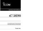
Step Sequencer64 J74.amxd – Note (pitch) view
The graphical user interface (GUI) of the device is dedicated in its largest part to the sequenced step information (pitch,
velocity, duration and envelopes). Around this there is quite a number of tabs, buttons and menu's which allow you
control and editing. Let's have a close look to the GUI and explain what every knob, control and button does.
[view] selector
This tab is used to switch the step information being shown, presenting the following information (“views”):
• Note Pitch
• Note Velocity (0-127)
• Note Duration (in 1/4 th units)
• The CC#1 envelope value (custom assignable – further in this document more about this)
• The CC#2 envelope value (custom assignable – same thing, see later)
Each of the 64 steps indeed contains and outputs these values. The [view] selector switches between the views (in
rotation fashion if automated). It is important to notice that only the view “in focus” (s e l e ct e d ) allows changes
via t he GUI. This re str ict ion d oe s no t app ly if you map the controls to a hardware controller: in this case
parameters can be modified independently of which view is selected. The “All” view acts as a summary (no
individual parameter GUI editing is possible when in this view).
[step ON/OFF] activators
The step sequencer has a dedicated [step ON/OFF] activator for each step. When a step activator is ON it is reported
in orange and the step will be allowed to play its information (note, velocity, duration, CC#1 and CC#2 envelope
values) when the turn comes. If a step activator is OFF it will be reported as gray and the step information will
be muted when the step turn comes.
Note: the step sequencer supports mapping and visual feedback on MIDI controllers. See next in this document for
details on how to set up a MIDI controller for this purpose.
StepSequencer64 J74 – Page 6
[seq active] field
The internal logic of the device is based on the daisy chaining of four coordinated 16-steps sequencers, playing in
round robin fashion (1-2-3-4-1-2-3-4-etc.). This behavior can be modified while going, using the [seq active] field.
This way the device can be set to run as a 16, 32, 48 or 64 step sequencer: a value of 4 (the default) activates all 4
sections, giving 64 steps. Similarly a value 3 gives you 48 steps (1 to 48), a value of 2 gives 32 (1-32) and of course a
value of 1 just runs the (first) 16 steps.
Chromatic sequencing (In-key mode)
The step sequencer can operate in chromatic and in-key modes. In chromatic mode (the default) all pitch values can
be programmed, with no specific restriction. In in-key mode pitch values will be constrained to a selected musical
scale. The mode in use is defined by the [chromatic/in-key] mode selector (the left-most button in the picture below).
When in-key mode is selected root and scale are defined by the combination of the [root] and [scale] settings. For
instance [root]=”B” and [scale]=”Minor” will define “B Minor” as the applied scale. In-key mode allows the step
sequencer to produce results consistently matching the harmonic context of your composition.
Per step pitch probabilistic variation: [modf%] toggle/selectors and [modf] probability distribution
On top of In-key mode, this step sequencer also provides the possibility of per-step musical variations in the pitch .
If you look at the GUI you can see underneath the row of the [step ON/OFF] activators an additional row of toggles,
the step probability selectors. This row is indicated by the [modf%] label. The toggles in this row define which step
will be subject to the probabilistic pitch variation.
How it works: when a step probability selector [modf%] is ON (in yellow, like for step 7 in the picture above) a pitch
modifier rule will be triggered for the step. The rule is defined by the following three components:
1. The [pitch] value programmed in the step itself (its note, as in the Note view). This value acts as the root
to be used for this step (overriding for the step the setting of the [root] menu, if in-key mode is also used).
2. The [scale] is used in combination with the [pitch] to define the set of possible output pitch values.
3. The [modf] menu settings defines the probability distribution to use.
Note: The In-key feature and the step pitch probabilistic variations are independent features. If you are using inkey mode and wish the per-step variations to remain in tune with the selected scale, set the pitch (of the steps
having the [modf%] toggle turned ON) to the same note as the [root] used for the in-key mode.
Example: with in-key set to ON, [root] = C and [scale] = “Minor”, any step having [modf%] turned ON will be in
tune with the key (C Minor) if their step pitch value is also a C (like C-2, C-1, C0, C1, etc.).
This is of course not the only way to use it. By setting the note pitch on the step to another root you can add
accidentals based on an harmonically related scale.
StepSequencer64 J74 – Page 7
The available probability is defined by the [modf] menu using the following probability schemes:
•
never, the modifier is bypassed altogether and the programmed step note pitch is played out (this is
equivalent to the situation of all modf% cells being unselected/gray). This is useful for quickly returning
to the original sequence from a variation being applied through one of the other probability schemes.
•
seldom-3, 50% chance of the first note in the scale, 25% of the second note in the scale, 25% of the third
note in the scale, 0% probability of any other note.
•
lite-3, 40% chance of the first note in the scale, 30% of the second note in the scale, 30% of the third note
in the scale, 0% probability of any other note.
•
lite-4, 40% chance of the first note in the scale, 20% of the second note in the scale, 20% of the third note
in the scale, 20% of the fourth note in the scale, 0% probability of any other note.
•
some-4, 25% chance of the first note in the scale, 25% of the second note in the scale, 25% of the third note
in the scale, 25% of the fourth note in the scale, 0% probability of any other note in the scale.
•
equal-5, 20% chance of the first note in the scale, 20% of the second note in the scale, 20% of the third
note in the scale, 20% of the fourth note in the scale, 20% of the fifth note in the scale, 0% probability of
any other note.
•
always-4, 0% chance of the first note in the scale, 25% of the second note in the scale, 25% of the third
note in the scale, 25% of the fourth note in the scale, 25% of the fifth note in the scale, 0% probability of
any other note.
An example may be better than 1,000 explanations. Let's say we have:
•
In key-mode turned ON.
•
The [root] is set to C.
•
The [scale] is set to “Minor”
•
Step 7 has the [modf%] probability selector set to ON (yellow).
•
Step 7 has pitch (in the sequence “Note” view) set to the note C (= the same root note of the in-key mode).
•
The [modf] menu is set to “always-4”
Effect of the feature:
The modifier rule will select a note from the C minor scale. The possible notes for the selections are in the set: C - D
-Eb - F - G - Ab – Bb (= the C minor scale). The adopted probability scheme (modf right menu) is “always-4”,
which means that there is a 0% chance of the first note in the scale (the root, the C itself) to be selected, 25% for the
second note in the scale (which is D), 25% for the third note in the scale (Eb), 25% for the fourth note in the scale (F)
and 25% for the fifth note in the scale (G).
When the step 7 turn comes the rule will “throw the dices” (weighted accordingly to the adopted probability
scheme) and select either a D, Eb, F or G for the pitch. As “always-4” gives equal probability to D, Eb, F and G and
excludes the step note C itself, this will statistically result in a different note played, each time the sequence is
repeated. As the pitch value was set to C, same as the [root] for the in-key mode, the variations will be in tune
with the rest of the sequence.
StepSequencer64 J74 – Page 8
[layers] and [a/m] mode selection
Multiple “layers” (8) are available in this step sequencer. L ayers can be used either as alternative m o n o p h o n i c
sequences or as multiple parallel parts (for polyphony). The [a/m] toggle defines which layering mode is selected.
When the [a/m] toggle is gray (not active, which is the default setting) only one layer is allowed to play. Each time
you press a different layer number button, the sequencer “switches” from layer to layer, changing the active
sequence to the last selected (with all other layers being muted).
Tip: you can use this way the layers for incremental changes of the same basic sequence, typically applying
changes only to a few automation envelopes values or on the notes pitch (for instance a layer may play a
sequence/arpeggio around a C minor chord and the next layer on a G minor chord). Each layer button acts in this
mode as a switch.
When the [a/m] toggle is yellow (active ) the sequencer operates with multiple running parallel sequences,
over imposed to each other. In this case the target device is supposed to support polyphony.
Tip: the sequencer can be used in this way to play “chords”. Each numbered layer button acts in this mode as a
toggle, each layer being selectable without disabling the others.
It is possible to scroll to a different layer without activating it. To change the displayed layer without activating
it use the [prev_seq] and [next_seq] buttons (on the right side of the device).
On the top-left of the sequencer, you can always see a little display named [seq nr] with a number. This always shows the
sequence layer being displayed. Refer to the layer button column to see what layer is playing.
Application: Let's say you are in the middle of an improvisation and got an idea about a new variation. You'd like to
make the changes but without everybody hearing the intermediate editing. In this case you can:
•
•
•
•
•
Start by making a copy of the playing sequence, with the [copy] button
Scroll to the next layer (without activating it) using the [next_seq] button
Use the [paste] button to paste the copied sequence on the selected layer (which is not active)
From now do your edits on the selected layer (without people hearing the changes).
At last activate the new layer with the corresponding numbered layer button.
StepSequencer64 J74 – Page 9
[direction] menu
The four sections of the sequencer (section 1 composed by steps 1-16, section2 by steps 17-32, section 3 by steps
33-48 and section 4 by steps 49-64) always follow the same direction. By default this is the usual “forward” (from
left, to right) time progression mode. Anyway this behavior can be changed using the [direction] menu. The
following five modes are available:
•
forward, the usual order (1, 2, 3 .... 62, 63, 64)
•
backward, each section is reverted resulting in 16, 15, …, 1, 32, 31, …,17, 48, 47, …,33, 64, 63, …, 49
•
back_and_forth, a bit funny one: sections are split in two 8-steps, played first forward, then backward
•
rotate, sections 1 and 3 play forward, sections 2 and 4 backward
•
random, as you would expect a random playback order
[loop-points] bars
Each of the four sections has an independent loop-point bar which is located at the top part of the sequencing area.
The bar allows you to define the start and stop step of the sequence during playback. When the last step will be
played the turn will jump to the first step again, without any pause. This allows you to create a poly-rhythmic effect.
Note: when more sections are active (32, 48 or 64 steps) a section always play 16 steps before moving to the next .
Pitch input to transpose the sequence in real time
A feature I miss in many sequencing products is the possibility o f transposing the pitch of the sequence in real
time using a MIDI keyboard as input. This feature is available on this step sequencer and when used turns the device
into a powerful, programmable and flexible real time 64-step arpeggiator.
Note: If you send a MIDI note to the device this note will not be used to “play” the device (as the sequencer is
there to generate notes itself), but, instead, it is used to transpose the pitch of sequence up or down, in real time.
How it works: the sequencer has a reference pitch defined as C2 (MIDI pitch value 48). If a MIDI note A#1 is received
in input (which is MIDI pitch value 46) this will cause a transpose of -2 for the entire sequence, as given by simple
formula [input – reference], in this case [46 – 48 = -2]. All notes in the sequence will be played transposed of -2, until,
of course, a new note is fired and a new pitch transpose defined accordingly.
Note: a note input can be sent at any moment, even half way the sequence. This gives an additional degree
of creativity.
StepSequencer64 J74 – Page 10
Envelopes (CC#1 and CC#2): the concept
The Step Sequencer 64 is in large part made to reflect the behavior of a typical analog step sequencer which uses
CV (Control Voltage) to control an external synthesizer. The simplest thing you could do with them is to have the
step sequencer CV modulating the synthesizer pitch (CV/Gate) of an oscillator. This is exactly what pitch,
velocity and duration are for, in the digital/MIDI world. So far, so good.
Another (slightly less intuitive) thing you could let an analog step sequencer and an analog synthesizer do is to use
the CV out of the sequencer to modulate a synthesis parameters on the synthesizer, such as the VCF cut-off on a
filter, the LFO rate or its intensity, or whatever else you come up with and has a point to attach the CV out to in.
The latter kind of things is the reason why the CC#1 and CC#2 “step envelopes” are available on this step sequencer:
to modulate parameters in Live using the M4L API capabilities!
Envelopes (CC#1 and CC#2): in practice
To have the CC#1 and/or CC#2 to work you need to drop the companion “Step CC#1.amxd” and “Step
CC#2.amxd” devices in the Liveset (anywhere is fine).
These two small devices do the following:
• They collect the modulation values generated by the step sequencer
• If required they do some input pre-processing on the input values (gain, offset, normalization 0. – 1. // 0–127)
• Use these to modulate a target parameter of choice on a device in the live set (chosen through the menus)
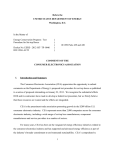
The example below shows the “Step Sequencer64 J74.amxd” (with selected view on the CC#1 envelope) and the
“Step CC#1.amxd” and “Step CC#2.amxd” chained behind it. In this example CC#1 is being used to modulate the
cut-off frequency of an instance of Live's Operator FM synthesizer.
The modulation happens through the “Step CC#1.amxd” device. The target device (Operator) and the
target parameter (“Filter Freq”) are selected using the menu's on the “Step CC#1.amxd” device. The CC#1 envelope
on the sequencer controls the modulation. Any change on the CC#1 envelope is immediately applied to the
modulation.
A similar mechanism is used for the CC#2 envelope. This is used to modulate the resonance of the same filter in the
same Operator instance, this time through the “Step CC#2.amxd” device.
StepSequencer64 J74 – Page 11
Please notice that on the target device the modulated parameters turn “gray” and the encoder will move according
to the CC#1 and CC#2 envelope generated values.
Other settings for (optional) processing of the CC#1 and CC#2 envelope values
Other settings on the “Step CC#1.amxd” and “Step CC#2.amxd” devices which may be useful:
•
static, is a test static entry value, used to set the target parameter is well mapped
•
gain, multiplies the input value by a given amount
•
offset, offsets the input (after the gain) by a given amount
•
off_fine, same as offset, but in the range 0. to 1.
•
normalize, toggles between output in the range 0. to 1. (typical of Ableton Live) and output in the range 0
to 127 (typical of MIDI hardware)
Tip: You can MIDI map these parameters. These can be a valuable and expressive aid to real-time performance.
The default settings on the CC-thru and CC-ON toggles are good for probably all common cases and won't
normally needed to be touched. In the remote case you need to, this is the two toggles in questions do:
•
If CC-thru is not selected (gray, default), any input CC value to the device will be silently dropped and
not passed through the device. If CC-thru is set to ON (yellow), input CC values will be passed transparently.
•
If CC-ON is not selected (gray, default), the CC#1 and CC#2 will only be used between the devices
for modulation. If activated (yellow) the CC#1 and CC#2 will be also sent as CC values (respectively on
CC21 and CC22). This is useful to be able to record the envelopes in MIDI clips (see paragraph on MIDI Clip
export).
StepSequencer64 J74 – Page 12
All-steps actions: modifiers and other buttons
On the right side of the device you have a set of buttons which can modify a given piece of information for all the
steps altogether (what I called the “all-steps modifiers”). The following actions are available:
•
Move all steps note pitch values up/down (equivalent action using the up/down arrows below the buttons)
•
Move all steps velocity values up/down
•
Move all steps duration values up/down
•
Move all steps CC#1 envelope values up/down
•
Move all steps CC#2 envelope values up/down
•
Shift all steps left/right. In this case only the step information will be moved, not the activators or probability
modifiers. An equivalent action can be performed using the left/right arrows below the buttons.
•
Generate a Random sequence. The “R” button generates a random sequence. Which information is affected
depends on the selected view: if a specific view (i.e. the velocity view) is selected, the “R” button only affects
that view values (velocities in this case); if the “All” view is selected all values will be randomized altogether.
Note: these actions actually modify the stored sequence (for the selected layer). So for instance a pitch up (or down)
action will change the pitch stored. This is different from the effect of a MIDI input note, which “momentarily”
transposes the pitch, leaving the stored sequence intact.
Tip: Try the Random function in combination with In-Key mode! This can be used for random melodic sequence
generation, in harmonic relation with the selected scale. A powerful source of inspiration.
Zoom/View buttons
The Zoom in/out buttons perform a piano keyboard zoom action. The View up/down buttons cause the piano
keyboard to scrll up/down of one octave. Similar actions can be done on the GUI using the mouse (same as in Live clip
piano roll).
StepSequencer64 J74 – Page 13
Section [copy_seq/paste_seq] and Sequence [Copy/Paste/Reset] buttons
The four sections of the sequencer (section 1 = steps 1-16, section 2 = 17-32, section 3 = 33-48 and section 4 = 4964) have a dedicated copy / paste button. This feature may appear simple and quite useless, but it can come handy
while editing and creating: it allows you to copy a section (i.e. section 1) and paste it onto another (i.e. Section 3),
a useful trick for creating a global “long” sequence (i.e. 64 steps) composed of variations of a shorter sequence.
Besides the section copy/paste actions you have also a full-sequence [Copy] and [Paste] button pair (right side of the
device). As you would expect, with these buttons you can perform a copy / paste of the entire 64 steps at once.
This is useful for duplicating a full sequence onto another layer (or another sequence preset). Finally, may you
need that, a [Reset] button is available: it will resets the current layer to have on all steps pitch at C2, velocity
level on 64 (50%), duration as 1 step (1 sixteenth), CC#1 to the max value and CC#2 to zero.
Step Sequencer 64 J74 internal “Sequence Presets”
Although Ableton Live internal preset system could be used, this often results in a quite unhandy way of managing a
large number of presets, like many sequences. For this reason the step sequencer has its own preset system. The
internal step sequencer preset system is lighter and more flexible.
A preset consist of a snapshot of the entire device, including all layers, step activators, step probability pitch
modifiers, menu's etc. and can be recalled without sound interruption.
The preset interface is very simple and is made as follows:
•
The yellow button are used to store a preset. There are sixteen presets on screen (more available if you
use an external controller to select preset numbers
•
The gray button are used to load a stored preset. There are sixteen presets on screen (more available if
you use an external controller to select preset numbers
•
The central block shows if a preset location is used (in dark yellow) and which preset is active (in red)
•
The [read] button opens a file dialog to select a preset bank file (extension .maxpresets) to load.
•
The [write] button opens a file dialog to save the current preset bank file (extension .maxpresets).
The [clear] button clears the current preset locations.
StepSequencer64 J74 – Page 14
Export of StepSequencer64 sequences to MIDI Clips
You can export the StepSequencer64 sequences as standard MIDI Clip in Live. To do this you just need to use the [Make
Clip] button on the GUI (right/top side).
This action will create a new MIDI clip in the same track of the StepSequencer64 containing all the note
information (pitch, timing, velocity, duration) as in your StepSequencer64 pattern. This allows you to use this
sequencer as an MIDI sketching/editor device and to consolidate your work into the more conventional Ableton
native clips.
Important: Currently Max for Live only exports MIDI notes into MIDI Clips, but no parameter automation (CC1# and
CC2# envelopes). This is not a limitation of the StepSequencer itself, but a generic Max for Live limitation. Anyway a
workaround to this is possible using MIDI recording in combination with MIDI CC's (Control Changes), in this way:
1.
Put the “Step Sequencer64 J74.amxd” on its own MIDI track (with no other device). Enable the [CCOn] toggle (yellow) on the Step Sequence (as previously explained, this enables MIDI CC for step
automation).
2.
Create a separate MIDI track for the played instrument and put in this track also the “Step
CC#1.amxd” and/or “Step CC#2.amxd” which allow the step automation. Arm this track.
3.
Use Live MIDI routing: On the track with the instrument (and “Step CC#1.amxd” and/or “Step
CC#2.amxd”) set “MIDI From” to be the track where the step sequencer is placed .
4.
Record MIDI Clips in the second track (the one with the instrument) : CC#1 as CC nr. 21, CC#2 as CC nr. 22.
5.
As “Step CC#1.amxd” and/or “Step CC#2.amxd” keep the mapping with the modulated parameters
they should not be removed from the track, unless you copy the recorded envelopes for MIDI CC 21 /
22 and paste them on the device parameter to be modulated . You can do this using Live MIDI editor
(select MIDI CC21, copy the envelope, paste it on the target parameter and so on).
StepSequencer64 J74 – Page 15
Integration of the StepSequencer64 with one or more external hardware controllers
Step Sequencer 64 device supports integration of an external controller Here information on how to set this up.
This step sequencer really shines once you drop the mouse/pointer and use a physical controller with encoders,
sliders and buttons to control it. The nice old way, the old-school way.
Tip: Do you have an APC40? If so, go directly to case D) described below!!!
There are basically four ways to make mappings between your controller and the step sequencer:
A) Rely on Ableton Live's MIDI/keyboard mappings. This is Live's built in approach, nothing new. In this case
you need to MIDI map each button/menu/slider, one by one, to the target parameter of the sequencer.
Mappings will be saved with the live set, but they will not be available if you start a new liveset from
scratch and load a new instance of the step sequencer. T h i s i s a bit unhandy and often not the
quickest way to achieve the level of integration I aim for. See next.
B) Use the “Step Surface.amxd” additional patch and its default mappings. The “Step Sequencer64
J74.amxd” has built-in MIDI mappings and responds to specific CC and/or notes when received. A small,
separate Max for Live add-on device, called “Step Surface.amxd” (instructions on this in Appendix 6) is used
to load (and if you need, customize) such mappings. Some MIDI routing is required to get the mappings
running (see Appendix 6).
C) Use the “Step Surface.amxd” additional patch with custom mappings. You can overrule the pre-defined
MIDI CC (and note) mappings in the device, by loading a custom surface definition in the “Step
Surface.amxd”. In this text file (must be .txt extension) you need to specify which CC or note you will
use to controls which parameter of the step sequencer. A procedure for making such file is provided in
Appendix 2. Once loaded on the “Step Surface.amxd”, this will override the step sequencer built in settings
and match the CC and notes you specified. Also, some MIDI routing is required to get the mappings running
(see Appendix 6).
D)
Use the “SS64-APC40-Surface.amxd” additional automap patch in combination with the APC40 controller.
The additional patch auto-maps all the parameters on the StepSequencer and PatDrummer devices to the
APC40 in a logical and powerful way (no routing or surface definition required in this case). For the instructions on
how to use the “SS64-APC40-Surface.amxd” with an APC40 look to the last chapter of this manual: “Using
the APC40 with SS64 GroveBox”.
StepSequencer64 J74 – Page 16
The Max for Live PatDrummer J74.amxd device
This device is a drum pattern-based box. The PatDrummer device combines on-the-fly pattern mixing with
the possibility of MAKING your own patters and on experimenting with them to create variations, newer
combinations or to alter playback in powerful ways (poly-rhythm, dynamics, groove) .
As the device can also export and import Pattern Banks, it can be used as both a live tool (a drum machine
sequencer) and as a powerful pattern editor to create a personal library of drum patterns.
PatDrummer generates MIDI notes and is made with Live Drum Racks in mind: the generated MIDI notes match
the ones the Drum Rack requires by default. Simply put a DrumRack behind this device and you are in business.
Important: this device requires a Max for Live license to run.
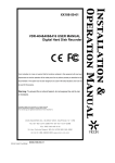
The Pattern Roll area (programming patterns)
The PatDrummer is in first place an editor and the Pattern Roll is the area where the making and modifying of
patterns takes place. It presents 10 sequencing rows, each one triggering a different drum part/velocity
combination. This grid is completed by the 16 columns: each one represents a step (in sixteenths), as in a sequencer.
When you see a yellow dot on a spot, such as row X/column Y, this means there is a drum trigger for part X at step Y.
To activate a drum trigger, at a given spot, just click on the spot in question. You will see a yellow dot appear. To
deactivate an existing trigger just click on the dot, and the trigger (the yellow dot) will be removed.
Row nr.
Row nr.
Row nr.
Row nr.
Row nr.
Row nr.
Row nr.
Row nr.
Row nr.
Row nr.
Steps
1 2 3 4 5 6 7 8 9 10 11 12 13 14 15 16
1________________________________________________ Kick Drum (high velocity)
2________________________________________________ Kick Drum (low velocity)
3________________________________________________ Snare Drum (high velocity)
4________________________________________________ Snare Drum (low velocity)
5________________________________________________ Closed Hats (high velocity)
6________________________________________________ Closed Hats (low velocity)
7________________________________________________ Open Hats (high velocity)
8________________________________________________ Open Hats (low velocity)
9________________________________________________ Percussion (high velocity)
10_______________________________________________ Percussion (low velocity)
The rows correspond to the following parts / velocity combinations (both customizable, see next for instructions):
•
•
•
•
•
Row 1: Kick Drum (high velocity, by default pitch is C1, velocity 100)
Row 2: Kick Drum (low velocity, by default pitch is C1, velocity 20)
Row 3: Snare Drum (high velocity, by default pitch is D1, velocity 100)
Row 4: Snare Drum (low velocity, by default pitch is D1, velocity 20)
Row 5: Closed Hats (high velocity, by default pitch is F#1, velocity 100)
StepSequencer64 J74 – Page 17
•
•
•
•
•
Row 6: Closed Hats (low velocity, by default pitch is F#1, velocity 20)
Row 7: Open Hats (high velocity, by default pitch is A#1, velocity 100)
Row 8: Open Hats (low velocity, by default pitch is A#1, velocity 20)
Row 9: Percussion (high velocity, by default pitch is A1, velocity 100)
Row 10: Percussion (high velocity by default pitch is A1, velocity 20)
As you have seen, even rows (2, 4, 6, 8 or 10) trigger the same drum part (MIDI note) as the odd row they
follow (counting from top to bottom). This is because the even rows are there for adding dynamics on top of the
odd rows: for instance taking a Snare part into account, you would typically set a main hit in row 3 (Snare part, high
velocity) and a rebound-hit in row 4 (same Snare sound, but lower velocity). This is a typical way of giving dynamics
by velocity.
Based on this logic we can group the 10 rows into 5 “ pairs” of rows, each pair given by triggers of the same drum
part (same output MIDI note) but at two distinct velocities: 1&2 would be the pair for the kick (1 is the high velocity
part, 2 the low velocity), 3&4 for the snare, 5&6 for the closed hats, 7&8 for the open hats and 9&10 for the
percussion's.
Pattern modifiers: shift, copy, paste, random and erase each pattern, for each part separately
Besides programming the triggers (yellow dots) on the Pattern-Roll, other features are available for manipulating
the patterns in creative ways. Some of these features are packed in the “s/c/r” column (using the tiny colored
buttons) on the right of the Pattern-Roll area (s/c/r stands for: shift/copy/random). These modifiers have the
following effect:
•
•
•
•
•
•
Shift a Pattern-pair left: light green button
Shift a Pattern-pair right: dark green button
Copy a Pattern-pair in memory: light brown button
Paste a Pattern-pair from memory into the corresponding row: yellow button
Generate a random Pattern-Pair: blue button
Erase a Pattern-Pair: gray button
The next picture shows you this portion of the GUI.
Tip: an interesting way to create syncopation is to shift a single part while leaving the other intact. This is specially true
for the Kick or the Snare parts, which most of the times hit on the main beats. Try a shift right (delay) on the kick in
real time, on a pattern which was going on for a while, and hear the result by yourself!
Note: the modifiers apply to each pattern pair individually. The only exceptions are the Copy, Paste, Random and Erase
tiny buttons for the hats area, which operate on the Hats-pattern (rows 5, 6, 7 and 8 altogether) and not on the
individual Closed-pattern and Open-pattern.
While one level of creativity is the making of patterns through the Pattern-Roll area (and doing some tweak using
StepSequencer64 J74 – Page 18
the Pattern-pair modifiers), another level of creativity is mixing those patterns (pattern-pairs) together. If you
look further you will see why groove combinations are almost endless (more than 40,000 combinations are
possible – no joke!).
How does this work? The PatDrummer has multiple numbered memory slots for each Pattern-pair. These slots can be
recalled and mixed. You can automatically rotate them (i.e. using Live's clip envelope automation) or randomly
trigger – one or all at once – using one of the buttons on the GUI. The next will describe one by one the possibilities.
Slot Number Boxes
You can find the memory [Slot Number Boxes] given in red on the “RP/VP” column.
The following are the available slots:
• Slots 1 to 11 for the Kick-pattern (first, red number box in the “RP/VP” column)
•
•
•
•
Slots 1 to 11 for the Snare-pattern (third, red number box in the “RP/VP” column)
Slots 1 to 23 for the Hats-pattern (fifth, red number box in the “RP/VP” column)
Slots 1 to 11 for the Perc-pattern (seventh, red number box in the “RP/VP” column)
Note: there is also a special extra slot “0” for each Pattern-pair. This is not editable and is just an empty slot.
Anyway this can be handy too! Drum parts which disappear, make also a groovy effect on an ongoing progression!
Note: it is important to underline the fact that slots can be recalled individually. This means the every slot
combination is a valid combination. For instance it is perfectly possible to have Kick from slot 1, Snare from slot 9,
Hats from slot 16 and Perc's from slot 2. This is actually why the number of possible combinations is so huge
(12*12*24*12 = 41,472)!
Random Pattern button
These action buttons allow you select randomly a Pattern-pair from any of the available slots (including the 0
slot), with instant effect. There is a button for each Pattern-pair and one for the entire Pattern-combination (all
rows). These buttons are located in the [Sel/Var] column, have the “-RP” suffix (R-andom P-attern) and have the
following logics:
• The Kick-RP button selects a random slot from the Kick-Pattern pair
•
•
•
•
•
•
The Snare-RP button selects a random slot from the Snare-Pattern pair
•
The Closed-RP button selects a random slot from the Closed-Pattern pair
The Open-RP button selects a random slot from the Open-Pattern pair
The Perc-RP button selects a random slot from the Perc-Pattern pair
•
The Pattern button selects a random pattern for each of the previously mentioned Pattern-pairs
Note: once you trigger a pattern, the slot number changes and the new pattern keeps playing until changed again.
One-time variation Pattern button
StepSequencer64 J74 – Page 19
These action buttons allow you to randomly trigger a Pattern-pair from any of the available slots (including the 0
slot) with instant but temporary (one time only) effect: the affected pattern changes but only for the remaining
part of the measure, automatically reverting to the slot number previously selected once the measure ends.
These buttons are useful to create breaks or short time changes. There is one of these buttons for each Patternpair. These buttons are located in the [Sel/Var] column and have the “-VP” suffix (V-ariation P-attern). This is the
applicable logics:
•
•
•
•
•
The Kick-VP button triggers a random slot from the Kick-Pattern pair, for the rest of the current measure
•
The Snare-VP button triggers a random slot from the Snare-Pattern pair, for the rest of the current measure
The Closed-VP button triggers a random slot from the Kick-Pattern pair, for the rest of the current measure
The Open-VP button triggers a random slot from the Kick-Pattern pair, for the rest of the current measure
The Perc-VP button triggers a random slot from the KickPattern pair, for the rest of the current measure
Periodic Random Pattern Number Boxes
Besides “action-based” pattern selections, as just described (such as manually select a different slot or push
a randomizer action button to get a new selection), you can also “plan” periodic pattern changes. This can be
particularly useful on parts such as the kick or the snare, to give those parts a bit of unpredictability and make them a
bit “funky”.
On the “RP/VP” column, immediately below each Slot Number Box (which, as explained, is in red color) you will
find another number box, this time colored in black: the Periodic Random Pattern Number Boxes. These number
boxes are the tool for setting periodic variations in motion. By setting a number (greater than 0), you specify
the period (in measures) applied to perform random pattern variation. The value 0 applies no periodic variation
(which is the default behavior). The variation is always applied once in the period, and reverted back to the
standard selection once the measure is finished (this goes own periodically as specified in the number box).
Example: Snare-pattern is set to slot 1 and its Periodic Random Number box set to 4. This means the pattern played
will be normally the one in slot 1 but, on each fourth measure, it will be replace by a randomly selected pattern, to
return on the pattern from slot 1 when the next measure starts. This logic will continue again and again (unless
changed).
Note: The count of the first measure is started from the moment you modify the Periodic Random Number box.
Tip: A useful approach is have periodic variations applied on different parts each with a different period. I
personally like to keep the hats grooving on the same pattern (period is 0, no variation) and set the snare on a
period of 4 and the kick (or perc) on an odd number (like 3 or 5). This makes things a bit funky (it's probably just my
taste anyway!).
StepSequencer64 J74 – Page 20
The Note Triggers, Kit/Trigger Transpose and Velocity Triggers
We have seen the main tools for programming and mixing patterns. Let's now look at the settings for the
actual individual drum triggers. The PatDrummer generates by default MIDI notes which exactly match the ones the
Drum Rack actually requires. These settings can be adjusted or completely modified if you wish to.
Changing the Note triggers
To change the trigger notes use the MIDI-note boxes in the column “Notes”. For each Pattern-row, you will find a
dedicated note box which defines the note trigger for each drum part. The red note boxes define the note trigger
for the high-velocity parts, the gray note boxes for the low-velocity parts. The last number box in the “Notes”
column allows you to transpose all the low-velocity triggers (gray number boxes) together, at once.
Note: Each number box for the Note Trigger is an independent definition. So it is possible to assign the high-velocity
row for a part to a note and the low-velocity row for the same part to another note. For instance you could assign the
kick high-velocity to C1 and the kick low-velocity to C#1. This makes possible the use of the 10 rows for 10
independent sounds (trading in the idea of dynamics by velocity), if you wish to!
Kit/Trigger Transpose number box
You can transpose all the notes used for the triggers at once, using the numbered box located on the bottom-left
of the device, under the little column “Mode”: a value set in here transposes all the parts of multiples of 16 notes.
Why blocks of 16? Because there are 16 pads visible in a DrumRack of Ableton Live and the idea is to have the
same drum-part-to-sample-type logic repeated on each 16-pads-wide view: pads 1 to 16, then 17-32, 33-48 and so
on. This way you can have multiple Kits loaded in a single DrumRack, one on top of the other (in block of 16 pads) .
So 0 means no shift, and the Kick note will be just C1 (36); a shift number set to 2, instead, will transpose the note
number for the kick to to G#3 (36+16*2 = 68 = G#3) and basically pickup the pads from the third Kit.
Changing the Velocities of the triggers
The velocities of the parts can be also set to custom values. There are many ways to do that in other sections of Live
as well (i.e. on the Drum Rack), but a quick way is to change these velocities is using the 10 encoders on the right
side of the device. In this case you modify the MIDI velocities sent, not the sample gains.
As you may have guessed, the first column of encoders applies to the triggers on “high” velocity (respectively rows
1, 3, 5, 7 and 9) while the second column to the triggers on “low” velocity (respectively rows 2, 4, 6, 8 and 10).
StepSequencer64 J74 – Page 21
Poly-rhythm controls: Number of Steps, Step Offset, Part Direction and Tempo
The number of steps for the entire pattern and/or for each individual part can be dynamically changed
from 16 (the default) to 1 step using the [Steps] number box. The entire pattern and/or each individual
part can also be shifted using the [Offset] number box, which moves the starting step of an offset (with 0
being the normal starting position).
The entire pattern Step Number is defined by the [Steps] number box, while the entire pattern Step Offset is defined
by the [Offset] number box. For each part the [Per Part Steps] and [Per Part Shift] are available on the “p/s” column
(p=part, s=shift) with dedicated number boxes.
You can modify the playback direction of each part. To do this use the two little arrows as depicted in the picture
below. By default the playback direction moves rightwards and can be changed anytime to move backwards.
You can also change the tempo of playback for a part (independently from the others) using the [-/N/+] controls for
(just above the little arrows for playback direction). The [-] slows down the tempo for the part (from 16 to 8t, from 8
to 4t and so on). The [+] increases the part tempo (from 16 to 16t, from 16t to 32 and so on). The [N] button always
returns the part tempo to the actual global tempo.
Tip: The use of these parameters allows you to create complex poly-rythmic sequences.
The Solo / Mute Mixer
The final output of the PatDrummer can also be manipulated using Solo and Mute buttons, positioned at the right
side of the device. These buttons are the equivalent of a small MIDI Mixer's Solo and Mute buttons, affecting
the MIDI output, not the audio output (as the PatDrummer produces MIDI, not audio).
The Mute Buttons show the name of the part they control, and are in light gray when not muted (parts outputs
MIDI) and dark gray when muted (part MIDI output is muted). These buttons are toggles, and affect only the part in
question (you can mute each part independently of the others).
The Solo Buttons are located just left of the Mute buttons and show only an “S”. When not active they are light
gray. When active they become shiny blue. These buttons act like switches and (may) affect other parts: when a part
is solo-ed the part in question will be the only one allowed to output MIDI and all other parts will be automatically
muted.
Tip: When improvising the use of solo and mute buttons are useful for short-term emphasis on given parts. Note:
When you press the [Instant Random Pattern button], the solo and mute settings are reset to defaults.
StepSequencer64 J74 – Page 22
Swing, Groove and Dynamics Functions
A Swing/Groove/Dynamics MIDI output effect is present at the output stage of the PatDrummer. This section
adds subtile delays to each part and at each step giving a “human” feel to the live generated drum patterns.
The three functions provide respectively:
•
Swing: a random fluctuation of the trigger time, independent for each part. Each time a new step is to
be played a small delay is added. This delay is selected randomly for each part separately, requiring
only the maximum delay range in input in milliseconds (dial [swing range] with 0 – 32ms range).
•
Groove: real drummer's performances have been used to extract timing (groove) schemes. Once selected
a [groove scheme] (from a set of 10 available), use the [groove amount] dial to progressively add this
groove to the pattern (value 0 to 100%).
•
Dynamics: a random fluctuation of the velocity, independent for each part. Each time a new step is to
be played the trigger velocity value is modified by a +/- random value. This value is selected randomly for
each part separately, requiring only the maximum velocity offset range in input (dial [dynamics range] with
0 – 32 as possible values, corresponding to -16/+16 offset range).
The following shows the swing/groove/dynamics GUI:
[kick bypass swing] -------->
<--------- [swing range]
<--------- [swing effects complete bypass]
[snare bypass swing] ------>
[clsd hats bypass swing] →
[open hats bypass swing]->
[perc bypass swing]-------->
<--------- [groove scheme] selector
<--------- [groove amount]
<--------- [dynamic range]
<--------- [mix reset to 50%-50%] button
<--------- [swing/groove mix]
Additional available controls:
•
[Mix level] between swing and groove timing effects. A mix set to 0% will only use swing. A mix set to
100% means only groove is applied. Anything in-between interpolates the values. A 50% – 50% mix is
useful as it still provides plenty of groove while adding a component of random (swing) variation.
•
[Mix level reset] button. Reset the [Mix level] to a 50% – 50% mix.
•
[Groove Scheme] selection. Using this small number box you can select among 10 different realdrummer groove performances to use a s basis for the groove amount.
•
An [effect bypass] which allow to toggle between swing/groove/dynamics “wet” and “dry” output
•
Per [voice swing bypass] toggles are available on the left side of the swing controls (just right of the mute
mixing controls). By default swing/groove is applied to all voices. If you bypass swing/groove for a
voice timing for that part will be 100% straight to the beat timing (Tip: try bypassing kick and snare, while
keeping swing for the hats).
StepSequencer64 J74 – Page 23
Create MIDI Clips from PatDrummer: the [Make Clips] button
If you are producing a track rather than performing live, it may be useful to have your patterns (made jamming
and editing in PatDrummer) as “plain” MIDI clips/files (.mid extension). In Ableton Live, for instance, it is nice to be
able to “move” to the Arrangement view at a given point to fine tune automation, variations etc (and remove all
Max for Live devices for better portability). Using the [Make Clip] button you can quickly export the patterns, as
they appear in PatDrummer's configuration, to a standard MIDI clip in Live.
This includes all the ten pattern parts (all five triggers/voices, both with high and low velocities). This tool also
allows you to export the subtle variations given by the swing/groove/dynamics settings with the MIDI Clip. The
result is a standard MIDI Clip.
Note: polyrhythm settings are not exported into the clip (that is: all parts are set with Number of Steps = 16, Offset =
0, Direction = forward, Tempo = Global Tempo). If you wish to consolidate the results of Polyrhythm settings record
the MIDI output of the track hosting the PatDrummer device on a second MIDI track (using Live I/O MIDI routing
functionality).
StepSequencer64 J74 – Page 24
Export and Import patterns in PatDrummer memory to/from MIDI clips/files: the “PatExport J74” Utility
In addition to the possibility of exporting the current PatDrummer edit to a MIDI clip (using the [Make Clip] button),
an external utility called “PatExport J74” is available for exporting all the patterns in PatDrummer's memory to MIDI
clips. This tool also allows you to import patterns from MIDI files into PatDrummer.
How to Export all the patterns to MIDI clips/files (.mid)
The utility allows you to export the patterns individually, as standard MIDI files. This applies to both Max for Live
AND standalone versions. Once the MIDI files have been created you can can drag them into Live as MIDI clips or
load them in any DAW as long as this supports standard MIDI files opening.
Here an example of export done using the standalone PatExport utility.
Procedure to follow:
1) Choose the directory for your exports clicking on the “Export Path” button. This must be a directory
for which you have write permissions. Here you will find your MIDI files (.mid) after completing the
export,
2) Select the PatDrummer bank you wish to export as MIDI files by clicking on the “Read Bank”
button and browsing/selecting the bank you need.
3) Do the export. You can either do specific slot exports or export all slots at once.
1.In the first case you need to click on the slot position which matches the pattern in question. For
instance [kick slot 7] will be the seventh slot in the KICK row.
2.In the second case you just click on the “Export All to .mid” and all the patterns will be
exported as separate MIDI files.
4) Once your patterns are exported (the increment bars, left to the rows, are all reporting as completed
and the info at the right of the “Export All to .mid” button reports [Done]) you can load them in your
DAW
In the case of Ableton Live this is extremely quick and simple. Open your liveset and browse to the export
directory where the MIDI files are located. Drag and drop them into Live and there you go!
StepSequencer64 J74 – Page 25
You do not need to drag them one by one! You can do as many you need with a single action. For instance (see below)
you can select all the Perc patterns and drag them together to the Live MIDI track you wish to use (in the picture
track “5 MIDI”). Drop them there and individual clips slots will be filled in with the clips.
Import from MIDI clips/files (.mid)
On the other hand there may be situations you like to add a MIDI clip/file as a pattern for jamming with it
in PatDrummer. The import section allows you to do that, loading (browsing or dropping) a standard MIDI file (.mid)
and then uploading it into a pattern bank at a specific slot (you need to choose the trigger note – or notes in case of
hats -and the pattern slot to go).
Note: in Live you can export a MIDI clip as MIDI file very easily. Select the MIDI clip, right click on it and from the
pop up menu choose “Export MIDI Clip”. This clip can be imported in a PatDrummer bank using the PatExport utility.
StepSequencer64 J74 – Page 26
Working with PatDrummer native Pattern Banks: [Update], [Copy/Paste] and [Read/Write]
Beside import/export to MIDI Clips and MIDI files, PatDrummer can also save and recall its entire memory (all the
slots, all the patterns) using its own “Pattern Bank” format (collection of patterns).
A Pattern Bank is a collection of patterns for all the voices (parts) and for all the slots. It is a file and it contains all
the patterns for the kick part (up to 11 slots), the snare part (up to 11 slots), closed hats & open hats (up to 23
slots) and percussion (up to 11 slots).
Default “read-only ” protection. Commit changes with [Update] and [Write] for bank saving
You should be aware of a few “rules” to successfully make and recall changes to PatDrummer Pattern Banks:
•
By default the patterns in a bank are read-only and changes you make while editing in PatDrummer are
not saved: if you make changes to a slot and then move to another slot, those changes will be lost. Same
result if you reload the Live set, even if the Liveset was saved.
•
How to commit changes while editing: The [Update] button will cause the current configuration to
be committed in the volatile memory of your computer (the RAM). This anyway will not save the bank
file. In other words, if you make changes and press [Update], you can move to another slot and later come
back to the same slot (the one you modified and committed) and you will find the changes you
committed. The [Update] action alone, though, will not save the changes in the Live set or the Pattern
Bank.
•
Save a Pattern Bank and save patterns as part of your Live set project: you can do both using the
[Write] button. If you write the Pattern Bank as a file (eventually overriding another file or creating a new
one) and then save the Live set, a future reload of the Live set will recall the saved Pattern Bank file (and
therefore your changes will be associated with the liveset).
•
You can load a Pattern Bank using the [Read] button. This will load the patterns in the slots of PatDrummer.
Important: In this logic there is NO Undo for changes in the Pattern-Roll if committed or saved, not even from the
Live's undo system (Live's does not “see” individual changes to the patterns, only to the slot numbers and Pattern
Bank file).
Location of editing /export/import commands on the GUI
On the rightmost side of the device you will find the mentioned editing/load/save buttons, in column.
Pattern Banks [Read/Write]
The actual [Read] and [Write] buttons for import/export of Pattern Banks are located in the leftmost column.
They allows you to keep your edits and reuse them anytime in the future:
•
•
•
To save the Pattern Bank use the [Write] button.
To load a Pattern Bank use the [Read] button.
To save pattern edits in your Live set, do a [Write] (eventually overwriting an existing Pattern Bank file)
Pattern Bank File names with BPM embedded
There is a handy little feature associated with Pattern Banks you should also be aware of: if you save a Pattern
Bank with a name including the part “- #<bpm_value>bpm” (where bpm_value is an integer between 20 and 480,
what the tempo speed of your liveset should be) in the name of the Pattern Bank file, you can save the BPM and
return to it automatically when the Pattern Bank is recalled ([Read] button). An example of a valid name with BPM
embedded: “Patterns-DnB-003 - #155bpm.txt”. Opening this Pattern Bank will set Live's tempo to 155 BPM.
StepSequencer64 J74 – Page 27
Integration of PatDrummer with one or more external hardware controllers
PatDrummer supports integration of an external controller in a way conceptually identical to the Step Sequencer
64 device. Here information on how to set this up.
Tip: Do you have an APC40? If so, go directly to case D) described below!!!
The possible approaches are:
A)
Rely on Ableton Live's MIDI/keyboard mappings. There by default if you like to do manual mappings.
B)
Use “PatSurface.amxd” and the default MIDI mappings which make the PatDrummer respond to specific
MIDI CC when received. As in the case of the Step Sequencer 64 these mappings are encoded on a
separate small Max for Live device, called “PatSurface.amxd”. These are ready-to-use if you can match
them exactly on your controller (see details in Appendix 3). In Appendix 7 an example of MIDI routing for
controlling PatDrummer in this case. If your controller cannot match these CC's, please see the next cases.
C)
Use the “Step Surface.amxd” additional patch with custom mappings. You can overrule the pre-defined
MIDI CC (and note) mappings in the device, by loading a custom surface definition in the “PatSurface.amxd”
device. This may cost a few minutes but it is a one time configuration only. A procedure for making
such file is provided in Appendix 4. In Appendix 7 an example of MIDI routing for controlling PatDrummer in
this case.
D) Use the “SS64-APC40-Surface.amxd” additional automap patch in combination with the APC40 controller.
The additional patch auto-maps all the parameters on the StepSequencer and PatDrummer devices to the
APC40 in a logical and powerful way, with no additional definition or routing required. For the instructions on how
to use the “SS64-APC40-Surface.amxd” with an APC40 look to the last chapter of this manual: “Using the
APC40 with SS64 GroveBox”.
Important : the PatDrummer and Step Sequencer 64 are made to be used together. So the built-in control
mappings are made to not overlap the hardware controller's required MIDI CC (and notes) for control.
StepSequencer64 J74 – Page 28
The MIDI standalone StepSequencer64 J74
The standalone version of the Step Sequencer 64 is almost identical to the Ableton Live / Max for Live plugin version
with a few conceptual changes required by its different integration approach:
•
It uses standard MIDI for communication. This applies to the target sequenced device as well as to
hardware controllers for control. In case you like to integrate this device with a DAW you can use internal
MIDI routing as available on a MAC through the IAC bus (native from Apple) and on Windows through
(freeware) add-on's such as MIDIOX or MIDI Yoke. Be aware of handling internal latencies. On modern
computer this shouldn't be an issue. If you experience latency issues try to apply latency
compensation on the target sequenced instrument receiving the Step Sequencer MIDI feed.
•
The concept of CC#1 and CC#2 envelopes shifts a bit. It does not point to target parameters of Live's plugins
anymore (as the Live API will not be available and Live is not anymore the exclusive environment) but
on “real” MIDI CC values (which can be specified in this case to be any custom numbers).
•
It does not require any additional software or license to run. It is a standalone desktop application
Features specific to the Standalone version
The standalone version has m o s t o f the features of Max for Live / Ableton Live version and you can refer to
the explanations and definitions provided on the “Step Sequencer 64 J74.amxd” dedicated chapter, while only being
aware of the following changes.
MIDI Integration and Routing
To get input and output in/to the Step Sequencer 64 J74 standalone version you need to setup the MIDI I/O
section which is located on the right-bottom portion of the device.
The following I/O are available:
•
•
CTRL1 IN. This is the input for a hardware controller dedicated to NON-step parameters and for which
there will be no visual feedback (echo). The setup of this port is optional, only required if you which to use
an external hardware controller as control surface (all functions can be piloted via the GUI/mouse as well)
CTRL2 IN. This is the input for a hardware controller dedicated to steps (what we called [step
ON/OFF] activators). For this surface there is the possibility of visual feedback (echo) through the ECHO
StepSequencer64 J74 – Page 29
OUT port. The setup of this port is optional, only required if you which to use an external hardware
controller as control surface (all functions can be piloted via the GUI/mouse as well). In general this port
should be different from the MIDI OUT port.
•
MIDI IN. This is the input for a keyboard, similar MIDI note input device or DAW output which allows you
to input notes to the step sequencer and in this way pilot its real-time pitch sequence transpose
feature. The setup of this port is optional, required only if you want to use the real-time pitch sequence
transpose feature.
•
Sync IN. This is the input available for MIDI sync information. It can be the same port used as other inputs
as long as it generates MIDI clock (from a DAW or even the PatDrummer, which generates an optional MIDI
Sync Out). The setup of this port is optional, required only if you want MIDI sync to be in place with other
devices.
•
CTRL OUT. This is the output used for the CC#1 and CC#2 envelopes of the sequencer. Use this to
modulate the target external MIDI device. You can use the same port as used for the MIDI OUT, if
you which to sequence and modulate the same target device. The setup of this port is optional, required
only if you want to use the CC#1 and/or CC#2 envelopes for CC number modulation.
•
MIDI OUT. This is the main output of the sequencer and is mandatory. All MIDI notes generated by
the sequencer will be sent out this port. For this port you can specify a MIDI channel (default is channel 1)
Note: all inputs are MIDI channel agnostic or, if required by your setup, also listening to MIDI channel 1.
Changes to the CC#1 and CC#2 envelopes
In the case of the standalone device Live's API enhancements are not available and the CC's generated by the
two envelopes (CC#1 and CC#2) will be exactly what their name suggests: MIDI Control Change numbers and
related modulated values.
You can use these to modulate quite al lot of stuff, as long as you know what your CC target must be. All
hardware synthesizers have a nice (some time cryptically written by engineers) MIDI implementation table, and it
should be fairly simple to retrieve the number of the CC to be generated to manipulate a given parameter.
As the CC's in question depend on your target, on the device GUI you will find two numbered boxes where you
can setup the CC numbers, labeled as [CC#1 out] and [CC#2 out] respectively. They are set to 21 and 22 by default,
but can be changed to anything you like.
Finally there are a couple of tiny buttons next to the numbered boxes: these buttons are made to test the configured
CC's and for the cases the target device allows you to “learn” a control for dynamic mappings (i.e. Some soft synth
allows you to learn dynamically a control CC for its own GUI – this is the typical case of having a DAW as the output of
the Step Sequencer, which hosts a soft synth plugin able to learn / be mapped dynamically). Pressing the [test CC#1]
while the device is NOT playing, allows you to send the CC used for the CC#1 envelope to the output for it to learn (it
will the only output, while the device is not playing, to avoid ambiguities). Similar behavior for the [test CC#2] button
and learning the CC#2 control by an external device.
StepSequencer64 J74 – Page 30
Transport buttons, Tempo and MIDI Sync IN
As the Step sequencer runs as a standalone it has its own tempo and transport controls. These are located on
the leftmost bottom portion of the GUI.
The following applies:
•
The larger button on the left is a [play/stop] toggle.
•
The button named [Restart] (left of the play/stop) allows you restart the sequence from step 1 at any time.
•
The toggle below the [play/stop] toggle defines if the sync mode will be the internal clock or the input
MIDI sync from the Sync IN selected MIDI input port.
•
The Tempo number box allows you to specify the tempo in the case of internal clock usage.
Integration of an external controler
Exactly the same philosophy described for the Max for Live version applies to the standalone, with only the
surface built-in and customizable surface mappings now collapsed with the sequencer itself.
Using the CTRL1 and CTRL2 input you can connect your controllers as MIDI input surfaces and the Step
Sequencer device will support the default mappings specified in Appendix 5. If you do not like those mappings,
want to edit the Step sequencer mapping (instead of matching them by changing your controller settings) you
can load a custom surface definition, which can be defined using the procedure described in Appendix 2. This
custom surface definition will be in all identical to the one you would make if using the Max for Live version.
In particular the native support for the Launchpad for control AND visual feedback of the steps still applies, even if you
are not using Ableton Live! In this case just connect the Launchpad (as it comes from the factory) as CTRL2 input and set
it as output on the ECHO OUT port, and you are done!
For all other features, the MIDI standalone version and Max for Live versions are IDENTICAL. Please refer to
the chapter explaining the Max for Live version for the details about all the features of the Step Sequencer 64.
StepSequencer64 J74 – Page 31
The MIDI standalone PatDrummer J74 pattern-based drumming box
The standalone version of the PatDrummer is almost identical to the Ableton Live / Max for Live plugin version
with a couple of conceptual changes:
•
It uses standard MIDI for communication. This applies to the target sequenced device as well as to
hardware controllers for control. In case you like to integrate this device with a DAW you can use internal
MIDI routing as available on a MAC through the IAC bus (native from Apple) and on Windows through
(freeware) add-on's such as MIDIOX or MIDI Yoke. Be aware of handling internal latencies. On modern
computer this shouldn't be an issue. If you experience latency issues try to apply latency
compensation on the target sequenced instrument receiving the PatDrummer MIDI feed.
•
It does not require any additional software or license to run. It is a standalone desktop application
Features specific to the Standalone version
The standalone version has m o s t o f the features of Max for Live / Ableton Live version and you can refer to
the explanations and definitions provided on the “PatDrummer J74.amxd” dedicated chapter, while only being
aware of the following changes.
MIDI Integration and Routing
To get input and output in/to the PatDrummer J74 standalone version you need to setup the MIDI I/O section which
is located on the right-bottom portion of the device.
StepSequencer64 J74 – Page 32
The following I/O are available:
•
Sync IN. This is the input available for MIDI sync information. It can be the same port used as other inputs
as long as it generates MIDI clock (i.e. from a DAW). The setup of this port is optional, required only if you
want MIDI sync to be in place with other devices.
•
CTRL IN. This is the input for a hardware controller dedicated to mapped controls. The setup of this port
is optional, only required if you which to use an external hardware controller as control surface (all
functions can be piloted via the GUI/mouse as well)
•
Sync OUT. This is an output for MIDI sync information, generated internally by the PatDrummer or (in case
a MIDI Sync is received) by the master clock device. The setup of this port is optional, required only if you
want send MIDI sync through this devices.
•
MIDI OUT. This is the main output of the device and is mandatory. All MIDI notes generated by
the PatDrummer will be sent out this port. For this port you can specify a MIDI channel (default is channel 1)
Important : all inputs are MIDI channel agnostic or, if required by your setup, also listening to MIDI channel 1.
Transport buttons, Tempo and MIDI Sync IN/OUT
As the PatDrummer runs as a standalone it has its own tempo and transport controls. These are located on
the leftmost bottom portion of the GUI.
The following applies:
•
•
•
•
•
•
The larger button on the left is a [play/stop] toggle.
The button named [Restart] (left of the play/stop) allows you restart the pattern from step 1 at any time.
The [Passive/Active] toggle defines if MIDI Sync is sent to the MIDI Sync OUT port
The [Sync Mode] toggle below the [Passive/Active] toggle defines if the sync mode will be the internal clock
or the input MIDI sync from the Sync IN selected MIDI input port.
The Tempo number box allows you to specify the tempo in the case of internal clock usage.
The Ext.delay number allows you to apply an additional latency to the clock, for compensating
“extreme” latency issues (the idea is to shift timing to get a pattern/measure back the drum set playing
the samples). Compensating latency on the target drum set device is generally a far better approach, if
possible.
Integration of an external controler
Exactly the same philosophy described for the Max for Live version applies to the standalone, with only the
surface built-in and customizable surface mappings now collapsed with the PatDrummer itself.
Using the CTRL IN input you can connect your controller as MIDI input surfaces and the PatDrummer device
will support the default mappings specified in Appendix 3. If you do not like those mappings, want to edit the
PatDrummer mapping (instead of matching them by changing your controller settings) you can load a custom
surface definition, which can be defined using the procedure described in Appendix 4. This custom surface definition
will be in all identical to the one you would make if using the Max for Live version.
StepSequencer64 J74 – Page 33
The Integrated standalone Groove Box J74
The Groove Box J74 device is a sort of bonus in this package and a little host on its own. If features the Step
Sequencer 64 and PatDrummer, together, compacted in one bigger GUI and able to load an AU (on the Mac) or
VST plugin (Windows and Mac) plugin for the sequencer part and individual drum samples for the drum part.
It's an instrument, a groove box and outputs an audio signal (single stereo output). Apart from MIDI Sync and
external controller support, it does not offer any form of integration.
WARNING: currently this device is to be considered experimental and as said a “bonus” to the package. It should work in
almost al environments, but as audio processing is involved, it has to deal with a far larger combination of hardware and
software which is beyond the reach of testing the author can do. Please do not expect this device to be as robust as the
other version! The author will not be considered responsible if you end up in problems using this device.
GUI layout
The following sections are packed in the GUI:
•
The Step Sequencer 64, which is on the top of the GUI.
•
The PatDrummer, which is on the left-central side of the GUI
•
The DrumSet, which is a little sampler loading individual samples. It just right of the PatDrummer part
•
The Plugin host, which is right of the DrumSet and can load an AU plugin (Mac only) or a VST plugin
•
The Mixer, which is located right of the Plugin host section
•
The Output (Audio Output & MIDI setup) section, located on the GUI rightmost end (right to the Mixer)
•
The Transport section, on the bottom, leftmost part of the device.
StepSequencer64 J74 – Page 34
Audio setup
Before being able to work (produce any sound with good quality and latency feel) the device audio setting must be
set up properly. To do this follow these steps:
1)
Click on the [Audio setup] button in the Audio Output and MIDI setup section of the GUI
2)
A new window will open, like in the picture below (Mac case on the left, Windows case on the right):
Modify this settings to match these recommendations:
•
Driver:
• On Mac = Core Audio
◦
•
•
On Windows = Supported ASIO driver for your setup
Scheduler in Overdrive: SELECTED (the toggle tick must show a cross)
•
Once you did set the previous properly, change the Audio Status top menu to “ON”
WARNING: if you encounter problems in this phase your hardware setup might not be supported.
StepSequencer64 J74 – Page 35
Step Sequencer64 part
This part of the device is functionally identical to the Max for Live or Standalone MIDI versions, with the
essential difference of not piloting an external device (plugin or MIDI) but the internal AU or VST plugin loaded in the
Plugin host section of the Groove Box device itself.
All features are identical to the mentioned versions, with the exception of:
•
How the CC#1 and CC#2 envelopes map to the Plugin's parameter. For those to be mapped see the
Plugin host section.
•
How the control surface can be loaded and customized. See the section below about hardware
controller integration and customization.
PatDrummer part
This device component is functionally identical to the Max for Live or Standalone MIDI versions, with the
essential difference of not piloting an external device (plugin or MIDI) but the internally loaded drum samples as
don in the Drumset sampler section of the Groove Box device itself.
All features are identical to the mentioned versions, with the exception on how the control surface can be loaded
and customized. See the section below about hardware controller integration and customization.
Drumset part
You are allowed to load a sample per drum part. You can drag and drop a sample from a file browser (Finder on
Mac, Explorer on Windows) to the named pad triggers or press the button [load] besides them and navigate to the
sample. You can test the drum part pressing the pad trigger on the GUI.
The drumset part is a very simple sampler. The only additional control is the [Length] encoder for each part (and the
one for all parts) which allows you to reduce the length of the sample (cut its playback).
StepSequencer64 J74 – Page 36
Plugin host
The simple Plugin host part can load a single AU or VST plugin. It shows up simultaneously 16 parameters,
tweakable individually through a dedicated and named knob, and allows mapping of the such parameters to the
CC#1 and CC#2 envelopes of the Step Sequencer.
How to load and set up a plugin:
1)
Press the button [Plugin Load] to open the file browser. Navigate and select your target plugin.
2)
Once the plugin has been selected, press the [Enable] toggle. This will enable the plugin and
automatically load its first 16 parameter names to the knobs.
3)
If you like you can open the plugin own window, pressing the [Plugin view/back] toggle, which opens /
closes the plugin window
4)
If you like you can map the CC#1 and CC#2 envelopes using the [Seq CC#1] and [Seq CC#2] number boxes.
A number (different from 0) maps the source CC envelope to the parameter number of the plugin. For
instance a [Seq CC#1] setting of 3 will map the envelope of CC#1 to the third parameter shown for the
plugin.
5)
If you like you can create a dynamic MIDI mapping for one of the knobs of your controller (set up on
the CTRL1 input) and a given parameter. To do this:
6)
1.
Press the [Learn ON/OFF] toggle on the Plugin section
2.
Move the target parameter knob
3.
Move the knob you like to use on your controller
The [param offset] number box allows you to navigate through the plugin parameters, giving the
shown parameter an offset. If the [param offset] is set to 15 this means the first encoder maps to the 16 th
parameter published by the plugin (1+15 = 16) and the last encoder the 31 st parameter published by the
plugin (16+15 = 32)
StepSequencer64 J74 – Page 37
The Mixer
A little mixer is included for controlling the drum parts individually and (in limited part) the plugin hosted. This
includes all the mixer knobs and buttons defined for the PatDrummer Max for Live and standalone versions and an
additional [PAN pot encoder] for pan settings (positioning in the stereo image) of each part.
The Output section
In this section you can setup and activate the audio output, load a custom surface definition to override the
default mappings, control the output level of the sequenced plugin and drum parts and set up MIDI for control
surfaces and Sync IN.
In particular:
•
The Audio setup section offers the possibilities to customize your hardware audio settings, and is a mandatory
configuration step the first time you run the Groove Box
•
MIDI setup is similar to the StepSequencer 64 standalone part concerning MIDI Sync IN and control surfaces,
including the following I/O:
StepSequencer64 J74 – Page 38
◦ CTRL1 IN. This is the input for a hardware controller dedicated to controls which are NOT steps and for
which there will be no visual feedback (echo). The setup of this port is optional, only required if you
which to use an external hardware controller as control surface (all functions can be piloted via the
GUI/mouse as well)
◦ CTRL2 IN. This is the input for a hardware controller dedicated to steps (what we called [step ON/OFF]
activators). For this surface there is the possibility of visual feedback (echo) through the ECHO OUT port.
The setup of this port is optional, only required if you which to use an external hardware controller as
control surface (all functions can be piloted via the GUI/mouse as well). In general this port should be
different from the MIDI OUT port.
◦ MIDI IN. This is the input for a keyboard, similar MIDI note input device or DAW output which allows you
to input notes to the step sequencer and in this way pilot its real-time pitch sequence transpose feature.
The setup of this port is optional, required only if you want to use the real-time pitch sequence transpose
feature.
◦ Sync IN. This is the input available for MIDI sync information. It can be the same port used as other inputs
as long as it generates MIDI clock (from a DAW or even the PatDrummer, which generates an optional
MIDI Sync Out). The setup of this port is optional, required only if you want MIDI sync to be in place with
other devices.
◦ CTRL OUT. This is the output used for the CC#1 and CC#2 envelopes of the sequencer. Use this to
modulate the target external MIDI device. You can use the same port as used for the MIDI OUT, if you
which to sequence and modulate the same target device. The setup of this port is optional, required only if
you want to use the CC#1 and/or CC#2 envelopes for CC number modulation.
•
The Custom Surface button allows you to load a custom surface definition for BOTH the Step Sequencer and
PatDrummer. The procedures given in Appendix 2 and 4 are applicable, with the only difference that all the
definitions must be saved in a single plain text (.txt extension) file. The consideration provided when
discussing the Step Sequencer 64 and PatDrummer in standalone version apply to this intact. Please refer to
those paragraphs for more information.
StepSequencer64 J74 – Page 39
Using the APC40 with SS64 GroveBox: Plug'n'Play auto-mapping
Added to the second release of SS64 Groove Box is the new “SS64-APC40-Surface.amxd” device. This tool
provides auto-mappings of all the parameters on the StepSequencer and PatDrummer devices to an APC40 (MK1
only, no MK2 support). The layout is plug and play and requires no specific MIDI routing . To use it:
1) Be sure the APC40 is working with the STANDARD Ableton Control Surface
2) Drop StepSequencer64 in the track you like.
3) Drop PatDrummer in the track you like (optional, if you like to use both)
4) To activate control use “Shift” + “Stop All Clips” button. Do the same to return to the default APC40 functionality.
Here an overview of the mappings:
Important: This layout is 100% compatible only with the default Ableton Live APC40 MIDI remote script as by Ableton
Live installation. This layout may or may not work with other custom or third party control surface definitions for the
APC40.
Next the layout will be graphycally presented, mentioning all the functions being mapped,
Note: the mappings include the use of a “special” shift button, different from the shift button used by Ableton Live
APC40 standard use. The SS64 special shift button is the REC button (while the SS64 mappings are active). See next
for its usage (in case of shifted mappings).
StepSequencer64 J74 – Page 40
StepSequencer: Step Activators, (Section) Copy/Paste, View Selector
StepSequencer: Values (Pitch, Velocity, Duration, CC1, CC2), Step Sections (1-8, 9-16, 17), Zoom:
StepSequencer64 J74 – Page 41
StepSequencer: Shift All Values, Preset Select, Loop Length, Direction of Play, Active Sequence Blocks (1 to 4):
PatDrummer: Trigger Editor, Part Selector, DrumRack Note Range, Random Pattern, Random Variation, Mixer
StepSequencer64 J74 – Page 42
PatD rummer : Patte rn Sel ec to rs, Number of Step s (Part and Patter n), Swin g, Device Select
StepSequencer64 J74 – Page 43
Appendix 1
These are the built-in mappings to which the "Step Sequencer64 J74.amxd" responds to, as activated when the “Step
Surface.amxd” is used (see Appendix 6):
•
Step activators. The following MIDI notes are used. In the picture a Launchpad which sends exactly these
notes when used in user mode 1 (remember to enable the MIDI output port of the Launchpad on the
preferences!).
•
Definition of the “Shift” button. A shift is used to expand the available controls combinations as available
number of knobs/button on common controllers is limited
[shift] = CC 63
•
Other controls. The following CC are pre-mapped (all MIDI CC's in combination with the given shift position):
[view selector] left = 65 + shift in position 1
[view selector] right = 67 + shift in position 1
[step1 – value of selected view] = 20 + shift in position 1
[step2 – value of selected view] = 21 + shift in position 1
[step3 – value of selected view] = 22 + shift in position 1
[step4 – value of selected view] = 23 + shift in position 1
[step5 – value of selected view] = 24 + shift in position 1
[step6 – value of selected view] = 25 + shift in position 1
[step7 – value of selected view] = 26 + shift in position 1
[step8 – value of selected view] = 27 + shift in position 1
[step9 – value of selected view] = 20 + shift in position 5
[step10 – value of selected view] = 21 + shift in position 5
[step11 – value of selected view] = 22 + shift in position 5
[step12 – value of selected view] = 23 + shift in position 5
[step13 – value of selected view] = 24 + shift in position 5
[step14 – value of selected view] = 25 + shift in position 5
StepSequencer64 J74 – Page 44
[step15 – value of selected view] = 26 + shift in position 5
[step16 – value of selected view] = 27 + shift in position 5
[step17 – value of selected view] = 20 + shift in position 2
[step18 – value of selected view] = 21 + shift in position 2
[step19 – value of selected view] = 22 + shift in position 2
[step20 – value of selected view] = 23 + shift in position 2
[step21 – value of selected view] = 24 + shift in position 2
[step22 – value of selected view] = 25 + shift in position 2
[step23 – value of selected view] = 26 + shift in position 2
[step24 – value of selected view] = 27 + shift in position 2
[step25 – value of selected view] = 20 + shift in position 6
[step26 – value of selected view] = 21 + shift in position 6
[step27 – value of selected view] = 22 + shift in position 6
[step28 – value of selected view] = 23 + shift in position 6
[step29 – value of selected view] = 24 + shift in position 6
[step30 – value of selected view] = 25 + shift in position 6
[step31 – value of selected view] = 26 + shift in position 6
[step32 – value of selected view] = 27 + shift in position 6
[step33 – value of selected view] = 20 + shift in position 3
[step34 – value of selected view] = 21 + shift in position 3
[step35 – value of selected view] = 22 + shift in position 3
[step36 – value of selected view] = 23 + shift in position 3
[step37 – value of selected view] = 24 + shift in position 3
[step38 – value of selected view] = 25 + shift in position 3
[step39 – value of selected view] = 26 + shift in position 3
[step40 – value of selected view] = 27 + shift in position 3
[step41 – value of selected view] = 20 + shift in position 7
[step42 – value of selected view] = 21 + shift in position 7
[step43 – value of selected view] = 22 + shift in position 7
[step44 – value of selected view] = 23 + shift in position 7
[step45 – value of selected view] = 24 + shift in position 7
[step46 – value of selected view] = 25 + shift in position 7
[step47 – value of selected view] = 26 + shift in position 7
[step48 – value of selected view] = 27 + shift in position 7
[step49 – value of selected view] = 20 + shift in position 4
[step50 – value of selected view] = 21 + shift in position 4
[step51 – value of selected view] = 22 + shift in position 4
[step52 – value of selected view] = 23 + shift in position 4
[step53 – value of selected view] = 24 + shift in position 4
[step54 – value of selected view] = 25 + shift in position 4
[step55 – value of selected view] = 26 + shift in position 4
[step56 – value of selected view] = 27 + shift in position 4
[step57 – value of selected view] = 20 + shift in position 8
[step58 – value of selected view] = 21 + shift in position 8
[step59 – value of selected view] = 22 + shift in position 8
[step60 – value of selected view] = 23 + shift in position 8
[step61 – value of selected view] = 24 + shift in position 8
[step62 – value of selected view] = 25 + shift in position 8
[step63 – value of selected view] = 26 + shift in position 8
[step64 – value of selected view] = 27 + shift in position 8
[seq_left – shift sequence left] = 65 + shift in position 2
StepSequencer64 J74 – Page 45
[seq_right – shift sequence right] = 67 + shift in position 2
[direction menu selector] = 59 + shift in position 1
[loopmode – number of steps in sequence ] = 59 + shift in position 2
[all_steps_value_up of selected view] = 64 + shift in position 2
[all_steps_value_down of selected view] = 66 + shift in position 2
[sequence_layer_plus] = 61 + shift in position 1
[sequence_layer_minus] = 62 + shift in position 1
[sequence_preset_plus] = 61 + shift in position 1
[sequence_preset_minus] = 62 + shift in position 1
[activate_layer_or_preset_selected] = 85 + any shift position
[active_sections_minus] = 108 + any shift position
[active_sections_plus] = 109 + any shift position
StepSequencer64 J74 – Page 46
Appendix 2
You can build your own mappings for the Step Sequencer 64 by creating a plain text file with the appropriate
definition. You can do it by editing the following information and saving the result as a file with a .txt extension. Load
this file on the “Step Surface.amxd” to activate the mappings.
// This is an example setup file for the MIDI mappings of the Step Sequencer 64 J74
// Define which control changes are sent from your MIDI controller and to which of the available
button/parameter/function they must be mapped.
// Note: Any line beginning with "//" is considered as a comment and gets not evaluated.
// Define <step mode>:
// This parameter defines if steps will be controlled using control changes (cc) numbers or notes numbers.
// In case of cc numbers the controls are assumed to be toggles.
// In case of note numbers the controls are assumed to be momentary and have a note on and off values.
// Syntax:
// smode = {cc|note}
smode = note
// Define the <shift button>
// The Step sequencer has up to 64 steps and lots of other knobs.
// Most MIDI controller do not have so many controls and buttons.
// So a "shift" button is defined to allow you to virtually increase the number of controls you can generate
for mappings.
// The shift has 8 state positions and is used in a circluar fashion.
// Each time you press the shift, the shift state value increases of 1.
// From state 8, by a further hit on the shift, the state will return to 1.
// In any definition (apart from the shift definition itself) the following keywords can be used:
// - Keyword "shift1" to specify a match to state 1
// - Keyword "shift2" to specify a match to state 2
// - Keyword "shift3" to specify a match to state 3
// - Keyword "shift4" to specify a match to state 4
// - Keyword "shift5" to specify a match to state 5
// - Keyword "shift6" to specify a match to state 6
// - Keyword "shift7" to specify a match to state 7
// - Keyword "shift8" to specify a match to state 8
// - Keyword "shift15" is a wildcard matching state 1 and 5
// - Keyword "shift26" is a wildcard matching state 2 and 6
// - Keyword "shift37" is a wildcard matching state 3 and 7
// - Keyword "shift48" is a wildcard matching state 4 and 8
// - Keyword "shift1357" is a wildcard matching state 1, 3, 5 and 7
// - Keyword "shift2468" is a wildcard matching state 2, 4, 6 and 8
// - Keyword "any" is a wildcard for matching any state
// Syntax (for the definition of the shift itself):
// shift = {NUMBER}
shift = 63
// Define <steps ON/OFF selectors>:
// This defines which MIDI control activates/mutes a given step in the sequence.
// Syntax:
StepSequencer64 J74 – Page 47
// step# = {NUMBER} {shift_state}
step1 = 64 any
step2 = 65 any
step3 = 66 any
step4 = 67 any
step5 = 96 any
step6 = 97 any
step7 = 98 any
step8 = 99 any
step9 = 60 any
step10 = 61 any
step11 = 62 any
step12 = 63 any
step13 = 92 any
step14 = 93 any
step15 = 94 any
step16 = 95 any
step17 = 56 any
step18 = 57 any
step19 = 58 any
step20 = 59 any
step21 = 88 any
step22 = 89 any
step23 = 90 any
step24 = 91 any
step25 = 52 any
step26 = 53 any
step27 = 54 any
step28 = 55 any
step29 = 84 any
step30 = 85 any
step31 = 86 any
step32 = 87 any
step33 = 48 any
step34 = 49 any
step35 = 50 any
step36 = 51 any
step37 = 80 any
step38 = 81 any
step39 = 82 any
step40 = 83 any
step41 = 44 any
step42 = 45 any
step43 = 46 any
step44 = 47 any
step45 = 76 any
step46 = 77 any
step47 = 78 any
step48 = 79 any
step49 = 40 any
step50 = 41 any
StepSequencer64 J74 – Page 48
step51
step52
step53
step54
step55
step56
step57
step58
step59
step60
step61
step62
step63
step64
=
=
=
=
=
=
=
=
=
=
=
=
=
=
42
43
72
73
74
75
36
37
38
39
68
69
70
71
any
any
any
any
any
any
any
any
any
any
any
any
any
any
// Define <Tab left|right buttons>:
// This buttons are used to change the active tab (all, note/pitch, velocity, duration, CC#1 and CC#2).
// Syntax:
// tableft = {NUMBER} {shift_state}
// tabright = {NUMBER} {shift_state}
tableft = 65 shift1357
tabright = 67 shift1357
// Define <enter_value_step control>:
// This defines which control to be mapped for entering step "values" (pitch, velocity, duration, CC#1 and
CC#2) depending on the selected/active tab.
// Syntax:
// estep1 = {NUMBER} {shift_state}
estep1 = 20 shift1
estep2 = 21 shift1
estep3 = 22 shift1
estep4 = 23 shift1
estep5 = 24 shift1
estep6 = 25 shift1
estep7 = 26 shift1
estep8 = 27 shift1
estep9 = 20 shift5
estep10 = 21 shift5
estep11 = 22 shift5
estep12 = 23 shift5
estep13 = 24 shift5
estep14 = 25 shift5
estep15 = 26 shift5
estep16 = 27 shift5
estep17 = 20 shift2
estep18 = 21 shift2
estep19 = 22 shift2
estep20 = 23 shift2
estep21 = 24 shift2
estep22 = 25 shift2
estep23 = 26 shift2
StepSequencer64 J74 – Page 49
estep24
estep25
estep26
estep27
estep28
estep29
estep30
estep31
estep32
estep33
estep34
estep35
estep36
estep37
estep38
estep39
estep40
estep41
estep42
estep43
estep44
estep45
estep46
estep47
estep48
estep49
estep50
estep51
estep52
estep53
estep54
estep55
estep56
estep57
estep58
estep59
estep60
estep61
estep62
estep63
estep64
=
=
=
=
=
=
=
=
=
=
=
=
=
=
=
=
=
=
=
=
=
=
=
=
=
=
=
=
=
=
=
=
=
=
=
=
=
=
=
=
=
27
20
21
22
23
24
25
26
27
20
21
22
23
24
25
26
27
20
21
22
23
24
25
26
27
20
21
22
23
24
25
26
27
20
21
22
23
24
25
26
27
shift2
shift6
shift6
shift6
shift6
shift6
shift6
shift6
shift6
shift3
shift3
shift3
shift3
shift3
shift3
shift3
shift3
shift7
shift7
shift7
shift7
shift7
shift7
shift7
shift7
shift4
shift4
shift4
shift4
shift4
shift4
shift4
shift4
shift8
shift8
shift8
shift8
shift8
shift8
shift8
shift8
// Define <Sequence shift left|right buttons>:
// This buttons are used to shift the sequence left or right
// Syntax:
// seqleft = {NUMBER} {shift_state}
// seqright = {NUMBER} {shift_state}
seqleft = 65 shift2468
seqright = 67 shift2468
// Define <Sequence forward mode>:
StepSequencer64 J74 – Page 50
// This button is used to change the cycle mode of the sequence
// Syntax:
// fwdmode = {NUMBER} {shift_state}
fwdmode = 59 shift1357
// Define <Sequence forward mode>:
// This continuous control is used to change the loop points of the sequence
// Syntax:
// loopmode = {NUMBER} {shift_state}
loopmode = 59 shift2468
// Define <All step values down/up>:
// This buttons are used to shift the sequence value up and down.
// The "q" version is 10 times quicker.
// Syntax:
// seqdown = {NUMBER} {shift_state}
// sequp = {NUMBER} {shift_state}
// qseqdown = {NUMBER} {shift_state}
// qsequp = {NUMBER} {shift_state}
seqdown = 64 any
sequp = 66 any
qseqdown = 127 any
qsequp = 127 any
// Define <Sequence Layer selectors up|down buttons>:
// This buttons are used to select a sequence layer (use the enter button to activate it)
// Syntax:
// lselup = {NUMBER} {shift_state}
// lseldown = {NUMBER} {shift_state}
lselup = 61 shift1357
lseldown = 62 shift1357
// Define <Preset selectors up|down buttons>:
// This buttons are used to select a preset (use the enter button to activate it)
// Syntax:
// pselup = {NUMBER} {shift_state}
// pseldown = {NUMBER} {shift_state}
pselup = 61 shift2468
pseldown = 62 shift2468
// Define <Enter button>:
// This button is used to activate selections of sequence layer or preset (depending on the previous
selection)
// Syntax:
// senter = {NUMBER} {shift_state}
senter = 85 any
// Define <clock echo>:
// This definitions are used only for the echo of clock in 1/8th. It defines which note numbers provide visual
feedback for clocking.
// Syntax:
StepSequencer64 J74 – Page 51
// clock# = {NUMBER}
clock1 = 100
clock2 = 101
clock3 = 102
clock4 = 103
clock5 = 104
clock6 = 105
clock7 = 106
clock8 = 107
// Define <Play/Stop button>:
// This button is used to start/stop the sequencer (only applies to the standalone version).
// Syntax:
// splay = {NUMBER} {shift_state}
splay = 111 any
// Define <Restart button>:
// This button is used to restart the sequence from the first loop point while playing (only applies to the
standalone version).
// Syntax:
// srstart = {NUMBER} {shift_state}
srstart = 110 any
// Define <Active sequence min/plus button>:
// This button is used to reduce/increase the step numbers in block of 16 (16/32/48/64).
// Syntax:
// samin = {NUMBER} {shift_state}
// saplus = {NUMBER} {shift_state}
samin = 108 any
saplus = 109 any
StepSequencer64 J74 – Page 52
Appendix 3
These are the built-in mappings to which the "PatDrummer J74.amxd" responds to, as activated when the
“PatSurface.amxd” is used (see Appendix 7):
•
Definition of the “Shift” button. A shift is used to expand the available controls combinations as available
number of knobs/button on common controllers is limited
[shift] = CC 63
•
Controls. The following CC are pre-mapped (all MIDI CC's in combination with the given shift position):
[pattern random combination] = 78 + any shift position
[kick random pattern] = 68 + any shift position
[snare random pattern] = 69 + any shift position
[hats random pattern] = 70 + any shift position
[percs random pattern] = 71 + any shift position
[kick one-time random pattern] = 79 + any shift position
[snare one-time random pattern] = 79 + any shift position
[hats one-time random pattern] = 80 + any shift position
[percs one-time random pattern] = 80 + any shift position
[kick shift left] = 81 + shift in position 2
[kick shift right] = 72 + shift in position 2
[snare shift left] = 82 + shift in position 2
[snare shift right] = 73 + shift in position 2
[closed hats shift left] = 83 + shift in position 2
[closed hats shift right] = 74 + shift in position 2
[open hats shift left] = 83 + shift in position 2
[open hats shift right] = 74 + shift in position 2
[percs shift left] = 84 + shift in position 2
[percs shift right] = 75 + shift in position 2
[create kick random pattern] = 98 + any shift position
[create snare random pattern] = 97 + any shift position
[create hats random pattern] = 96 + any shift position
[create percs random pattern] = 95 + any shift position
[kick high velocity level] = 54 + any shift position
[snare high velocity level] = 55 + any shift position
[closed hats high velocity level] = 56 + any shift position
[open hats high velocity level] = 56 + any shift position
[percs high velocity level] = 57 + any shift position
[kick solo] = 72 + shift in position 1
[kick mute] = 81 + shift in position 1
[snare solo] = 73 + shift in position 1
[snare mute] = 82 + shift in position 1
[hats solo] = 74 + shift in position 1
[hats mute] = 83 + shift in position 1
[percs solo] = 75 + shift in position 1
[percs mute] = 84 + shift in position 1
[kick periodic variation box] = 50 + any shift position
StepSequencer64 J74 – Page 53
[snare periodic variation box] = 51 + any shift position
[hats periodic variation box] = 52 + any shift position
[percs periodic variation box] = 53 + any shift position
[pattern play start/pause] = 99 + any shift position
[pattern play restart] = 77 + any shift position
Note: the [pattern play start/pause] and [pattern play restart] only apply to the standalone version.
StepSequencer64 J74 – Page 54
Appendix 4
You can build your own mappings for the PatDrummer by creating a plain text file with the approapriate definition. You
can do it by editing the following information and saving the result as a file with a .txt extension. Load this file on the
“PatSurface.amxd” to activate the mappings.
// This is an example setup file for the MIDI mappings of the PatDrummer J74
// Define which control changes are sent from your MIDI controller and to which of the available
button/parameter/function they must be mapped.
// Note: Any line beginning with "//" is considered as a comment and gets not evaluated.
// Define a <shift button>
// Your MIDI controller may not have so many controls/buttons as this device requires for proper control.
// So let's define one of your controllers button has a "shift" button to virtually increase the number of
controls you can map.
// In the following definitions use the following as possible states:
// shift1, to select the shift first position
// shift2, to select the shift first position
// any to select any shift position (the shift position will be ignored)
// Syntax: shift = {NUMBER}
// Example: shift = 63
shift = 63
// Define a <input mode>
// You can define if the input will be based on control changes (cc) or midi notes.
// Syntax: pmode = {note|cc}
// Example: pmode = cc
pmode = cc
// Define <Play/Stop control>:
// Defines the control for toggling between Playing and Stopped transports (only on Standalone version)
// Syntax: pplay = {NUMBER} {shift_state}
pplay = 99 any
// Define <Restart control>:
// Defines the control for transport Restart (only on Standalone version)
// Syntax: rplay = {NUMBER} {shift_state}
rplay = 77 any
// Define <All Pattern randomizer control>:
// Defines the control for Pattern Randomizer
// Syntax: patrand = {NUMBER} {shift_state}
patrand = 78 any
// Define <Kick Pattern randomizer control>:
// Defines the control for Pattern Randomizer on Kick part
// Syntax: krand = {NUMBER} {shift_state}
krand = 68 any
// Define <Snare Pattern randomizer control>:
StepSequencer64 J74 – Page 55
// Defines the control for Pattern Randomizer on Snare part
// Syntax: srand = {NUMBER} {shift_state}
srand = 69 any
// Define <Hats Pattern randomizer control>:
// Defines the control for Pattern Randomizer on Hats part
// Syntax: hrand = {NUMBER} {shift_state}
hrand = 70 any
// Define <Percs Pattern randomizer control>:
// Defines the control for Pattern Randomizer on Percs part
// Syntax: prand = {NUMBER} {shift_state}
prand = 71 any
// Define <Kick Pattern variation/one time randomizer control>:
// Defines the control for Pattern Randomizer on Kick part
// Syntax: krand = {NUMBER} {shift_state}
vkrand = 79 any
// Define <Snare Pattern variation/one time randomizer control>:
// Defines the control for Pattern Randomizer on Snare part
// Syntax: srand = {NUMBER} {shift_state}
vsrand = 79 any
// Define <Hats Pattern variation/one time randomizer control>:
// Defines the control for Pattern Randomizer on Hats part
// Syntax: hrand = {NUMBER} {shift_state}
vhrand = 80 any
// Define <Percs Pattern variation/one time randomizer control>:
// Defines the control for Pattern Randomizer on Percs part
// Syntax: prand = {NUMBER} {shift_state}
vprand = 80 any
// Define <Shift Kick Left/Right control>:
// Defines the controls for shifting the kick part left/right
// Syntax: ksleft = {NUMBER} {shift_state}
// Syntax: ksright = {NUMBER} {shift_state}
ksleft = 81 shift2
ksright = 72 shift2
// Define <Shift Snare Left/Right control>:
// Defines the controls for shifting the snare part left/right
// Syntax: ssleft = {NUMBER} {shift_state}
// Syntax: ssright = {NUMBER} {shift_state}
ssleft = 82 shift2
ssright = 73 shift2
// Define <Shift Closed Hats Left/Right control>:
// Defines the controls for shifting the closed hats part left/right
// Syntax: hsleft = {NUMBER} {shift_state}
StepSequencer64 J74 – Page 56
// Syntax: hsright = {NUMBER} {shift_state}
hsleft = 83 shift2
hsright = 74 shift2
// Define <Shift Open Hats Left/Right control>:
// Defines the controls for shifting the open hats part left/right
// Syntax: osleft = {NUMBER} {shift_state}
// Syntax: osright = {NUMBER} {shift_state}
osleft = 83 shift2
osright = 74 shift2
// Define <Shift Percs Left/Right control>:
// Defines the controls for shifting the percs part left/right
// Syntax: psleft = {NUMBER} {shift_state}
// Syntax: psright = {NUMBER} {shift_state}
psleft = 84 shift2
psright = 75 shift2
// Define <Kick Random sequence control>:
// Defines the controls for a random kick part
// Syntax: kseqrnd = {NUMBER} {shift_state}
kseqrnd = 98 any
// Define <Snare Random sequence control>:
// Defines the controls for a random snare part
// Syntax: sseqrnd = {NUMBER} {shift_state}
sseqrnd = 97 any
// Define <Hats Random sequence control>:
// Defines the controls for a random Hats part
// Syntax: hseqrnd = {NUMBER} {shift_state}
hseqrnd = 96 any
// Define <Percs Random sequence control>:
// Defines the controls for a random Percs part
// Syntax: pseqrnd = {NUMBER} {shift_state}
pseqrnd = 95 any
// Define <Kick Hi-Lo-vel control>:
// Defines the controls for velocity control of the kick part
// Syntax: khivel = {NUMBER} {shift_state}
khivel = 54 any
// Define <Snare Hi-Lo-vel control>:
// Defines the controls for velocity control of the snare part
// Syntax: shivel = {NUMBER} {shift_state}
shivel = 55 any
// Define <Closed Hats Hi-Lo-vel control>:
// Defines the controls for velocity control of the Closed Hats part
// Syntax: hhivel = {NUMBER} {shift_state}
StepSequencer64 J74 – Page 57
hhivel = 56 any
// Define <Open Hats Hi-Lo-vel control>:
// Defines the controls for velocity control of the Open Hats part
// Syntax: ohivel = {NUMBER} {shift_state}
ohivel = 56 any
// Define <Percs Hi-Lo-vel control>:
// Defines the controls for velocity control of the Percs part
// Syntax: phivel = {NUMBER} {shift_state}
phivel = 57 any
// Define <Kick Solo control>:
// Defines the controls for solo action on the kick part
// Syntax: ksolo = {NUMBER} {shift_state}
ksolo = 72 shift1
// Define <Kick Mute control>:
// Defines the controls for mute action on the kick part
// Syntax: kmute = {NUMBER} {shift_state}
kmute = 81 shift1
// Define <Snare Solo control>:
// Defines the controls for solo action on the snare part
// Syntax: ssolo = {NUMBER} {shift_state}
ssolo = 73 shift1
// Define <Snare Mute control>:
// Defines the controls for mute action on the snare part
// Syntax: smute = {NUMBER} {shift_state}
smute = 82 shift1
// Define <Hats Solo control>:
// Defines the controls for solo action on the Hats part
// Syntax: hsolo = {NUMBER} {shift_state}
hsolo = 74 shift1
// Define <Hats Mute control>:
// Defines the controls for mute action on the Hats part
// Syntax: hmute = {NUMBER} {shift_state}
hmute = 83 shift1
// Define <Percs Solo control>:
// Defines the controls for solo action on the Percs part
// Syntax: psolo = {NUMBER} {shift_state}
psolo = 75 shift1
// Define <Percs Mute control>:
// Defines the controls for mute action on the Percs part
// Syntax: pmute = {NUMBER} {shift_state}
pmute = 84 shift1
StepSequencer64 J74 – Page 58
// Define <Auto Variation Kick control>:
// Defines the controls for pattern automatic variation on the kick part
// Syntax: kavar = {NUMBER} {shift_state}
kavar = 50 any
// Define <Auto Variation Snare control>:
// Defines the controls for pattern automatic variation on the snare part
// Syntax: savar = {NUMBER} {shift_state}
savar = 51 any
// Define <Auto Variation Hats control>:
// Defines the controls for pattern automatic variation on the hats part
// Syntax: havar = {NUMBER} {shift_state}
havar = 52 any
// Define <Auto Variation Percs control>:
// Defines the controls for pattern automatic variation on the percs part
// Syntax: pavar = {NUMBER} {shift_state}
pavar = 53 any
StepSequencer64 J74 – Page 59
Appendix 5
These are the mappings to which the "Step Sequencer64 J74" standalone responds to (via its CTRL2 IN) :
•
Step activators. The following MIDI notes are used. In the picture a Launchpad which sends exactly these
notes when used as a standalone MIDI controller (which means not through Ableton Live surface definition
and integration).
•
Definition of the “Shift”. Same as provided in Appendix 1 under the tab “Definition of the Shift button”.
•
Other controls. Same as provided in Appendix 1 under the tab “Other controls”.
StepSequencer64 J74 – Page 60
Appendix 6
Example of MIDI Routing in Live for external controller hardware integration with the StepSequencer64 in
combination with the StepSurface.amxd device. The routing is not required when using the APC40 plug and play
mappings.
Here an example using a Novation Launchpad (for the steps) a Korg NanoKontrol for the other knobs/buttons,
plus a MIDI keyboard for pitch input (real time transpose of the sequence).
•
•
Track 1 - Step Sequencer (“Step Sequencer64 J74.amxd")
If you require modulation using the CC#1 and CC#2 envelopes/devices, the add-ons “Step CC#1.amxd”
and “Step CC#2.amxd” (chained behind the step sequencer) can be placed here as well.
◦ MIDI From = No input (note: other tracks will be set to send MIDI to this track – see next)
◦ MIDI To = The track hosting the instrument you want to sequence (in this example Track 5)
◦ Monitor = IN
◦ “Step CC#1.amxd” and “Step CC#2.amxd” menu select target parameters for CC#1 and CC#2 envelopes
•
Track 2 – Step Surface (“Step Surface.amxd") device
If you do not use a Launchpad and/or want to use custom mappings (see Appendix 2) you will need to
load your surface definition here, otherwise you do not need to do anything. This track will be used to
get the input for the [step ON/OFF] activators and to get the output notes back to your controller, for
visual feedback (the Launchpad in this example, where step on means led in red).
◦ MIDI From = Controller for steps (i.e. Launchpad – user mode 1 selected)
◦ MIDI To = Controller for steps (i.e. The same Launchpad – comment: in the case of a Launchpad this is
not a MIDI loop as the device uses this for visual feedback)
◦ Monitor = IN
•
Track 3 - no device
Used to have a separate controller for the other controls of the Step sequencer (not being the [step
ON/OFF] activators).
◦ MIDI From = Controller (i.e. NanoKontrol with CC's configured as in Appendix 1)
◦ MIDI To = Track 1 (the track hosting the Step Sequencer)
◦ Monitor = IN
•
•
Track 4 - no device
Used to have a separate keyboard for pitch shifting (transpose).
◦ MIDI From = MIDI Keyboard or controller generating MIDI notes
◦ MIDI To = Track 1 (the track hosting the Step Sequencer)
◦ Monitor = IN
•
•
•
Track 5 – target Instrument
The sequenced instrument and its audio output.
•
◦ MIDI From = No input (Track 1 sends already input to this track)
◦ Audio to = Master (or whatever you need it to be)
◦
Monitor = IN
StepSequencer64 J74 – Page 61
Note: this setup can even be expanded, having more tracks in the same fashion of track 3 or 4 in this example (for
instance for sending controlling CC's from different controllers devices like in track 3 or MIDI pitch input like in track 4).
The following shows the routing on the Live's Mixer:
Track1 devices: StepSequencer64, StepCC#1, StepCC#2
Track2 devices: StepSurface
Track3 devices: empty
Track4 devices: empty
Track5 devices: target instrument to be sequenced (Operator in this example)
StepSequencer64 J74 – Page 62
Appendix 7
MIDI Routing in Live for external controller hardware integration with PatDrummer in combination with the
PatSurface.amxd device. The routing is not required when using the APC40 plug and play mappings.
This is quite simple. Here an example using a generic controller sending CC numbers like a Korg NanoKontrol.
•
Track 1 - PatDrummer (“PatDrummer J74.amxd")
◦ MIDI From = No input (note: track 2 will be set to send MIDI to this track for control – see next)
◦ MIDI To = track hosting the Drum Rack or instrument you want to sequence (in this example Track 3)
◦ Monitor = IN
•
•
Track 2 – PatSurface (“PatSurface.amxd") device
This track will be used to get and map the controllers input to the PatDrummer.
◦ MIDI From = Controller (i.e. a NanoKontrol)
◦ MIDI To = PatDrummer's track, which in this example is Track 1.
◦ Monitor = IN
•
•
Track 3 – Target Drum Rack (or Instrument)
The sequenced instrument and its audio output.
•
◦ MIDI From = No input (Track 1 sends input to this track)
◦ Audio to = Master (or whatever you need it to be)
◦ Monitor = IN
Note: this approach is not exclusive in the use of a hardware controller. You can decided to use some buttons
and knobs for the PatDrummer and some other knobs for the Step Sequencer, for instance. In this case just
use the controller as MIDI input device multiple times! As long as you do not overlap mappings (such as in the case
of default mappings for the Step Sequencer 64 and PatDrummer) things will work fine.
The following picture shows the routing we just described in Live.