1
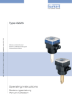
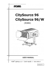
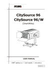
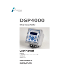
CombiDancer
Infra-Red
Vortex-Evaporator
User manual
Version 3.4
Seestrasse 204a, CH-8806 Baech / SZ , Switzerland
Tel. +41 44 786 80 20, Fax +41 44 786 80 21
E-mail: [email protected], Internet: http://www.hettich-ag.ch
Table of contents
1.
Operating principle, installation and first steps
4
1.1
1.2
1.3
1.4
1.4.1
1.4.2
1.4.3
1.4.4
1.4.5
1.4.6
1.5
1.5.1
1.5.2
4
4
6
6
6
8
9
10
12
13
13
13
14
1.5.3
1.6
1.7
Operating principle
Safety instructions
Package contents
The CombiDancer Infrared Vortex Evaporator
Device construction
CombiDancer control panel
Vacuum chamber
Sample racks
PoleStar cold trap
Vacuum pump
Installation of the CombiDancer
Connecting diaphragm pump and cold trap
Activation of remote operation for the Vacuubrand
PC2003/2004 VARIO diaphragm pump
Setting up the PoleStar cold trap
The CombiDancer Program
Device specifications
2.
Working with the CombiDancer
18
2.1
2.2
2.3
2.3.1
2.3.2
2.3.3
2.3.3.1
2.3.4
Control panel
Operation parameter input
Display
Display of the current sample number
Cold trap status
Pump status
Pump operation modes
Statuses of the valves and the key-operated switch, of the
PC-access and the CombiDancer
Multifunction button assignment
Creating a program
Time Menu
Vortex Menu
Temperature Menu
Pump Menu
Program Menu
Accessing the Program Menu
Storing and recalling a SINGLE Program
The Multi Menu
Recalling an existing program (MULTI)
Creating and editing a Multi Program
Storing a Multi Program
Deleting a Multi Program
Set value overview (VAL button)
18
19
20
21
21
21
22
2.3.5
2.4
2.4.1
2.4.2
2.4.3
2.4.4
2.4.5
2.4.5.1
2.4.5.2
2.4.5.3
2.4.5.4
2.4.5.5
2.4.5.6
2.4.5.7
2.4.6
2
14
15
17
23
25
25
25
27
28
29
31
31
32
33
33
34
37
38
38
2.4.7
2.4.7.1
2.4.7.2
2.4.7.3
2.4.7.4
2.4.7.5
Main Setting Menu
Temperature Submenu
External Units Submenu
Program Setting Submenu
PC Access Submenu
Configuration Submenu
Appendix A
Appendix B
Appendix C
Appendix D
Appendix E
:
:
:
:
:
39
40
41
42
43
44
ERROR-Codes
Spare parts list (electrical)
Spare parts list (mechanical)
Spare parts list (exchange)
Infrared spectrum
3
45/46
47
48
48
49
1. Operating principle, installation and first steps
1.1 Operating principle
Thank you for choosing the CombiDancer Infrared Vortex Evaporator; this device has
been designed to suit the most demanding requirements and to ensure the highest
flexibility for the evaporation of solvents using various types of sample tubes,
microtiter or deepwell plates.
The operating principle is a combination of heating, vortex and vacuum as a function
of time. These parameters can be combined into a maximum of 99 single-level
programs, i.e. 26 multi-level programs, allowing complex solvent mixtures to
evaporate quickly and gently.
The CombiDancer can accommodate up to 4 deepwell plates or microtiter plates.
Special racks can also accommodate HPLC-vials or other larger containers, such as
Falcon tubes for instance.
The vacuum can be adjusted using a diaphragm pump or a rotary vane pump.
Infrared lamps located in the lid heat the samples. An independent compartment
heater prevents the condensation of solvents with high boiling point in the vacuum
chamber. The actual temperature can be measured directly in the sample or in the
rack by means of a PTFE-coated temperature sensor. All parameters can be
programmed and controlled separately.
There are no rotating parts in the CombiDancer. Vortex of the samples is achieved by
means of a magnetic drive. No balancing of the samples required.
Picture 1.1 shows the CombiDancer with PoleStar cold trap and Vacuubrand
PC-2003 VARIO diaphragm pump.
1.2 Safety instructions
The CombiDancer Infrared Vortex Evaporator is a state of the art, reliable
product; however, it may lead to hazards for the user or a third party if it is not
used by trained personnel, if used improperly, or if the user does not observe
instructions.
Operating instructions of the CombiDancer must be read and observed
before the device is put into operation.
Besides operating instructions and regulations regarding prevention of
accidents, the universally recognized technical standards for safe
working conditions have to be observed at all times. In addition to the
operating instructions, the current national regulations concerning
prevention of accidents and environmental care also have to be
observed.
4
Picture 1.1: CombiDancer
and the PoleStar cold trap
with Vacuubrand PC-2003 VARIO diaphragm pump
Only connect devices to a grounded electrical outlet, using power cords
corresponding to the instructions. Never use damaged cables. Damaged
or insufficient grounding involves danger of life.
Attention must be paid to the instructions concerning AC power and
power consumption.
When the CombiDancer is transferred from a cold place to the
laboratory, condensation may appear on the device. In such a case,
allow it to acclimatize before operating.
Attention must be paid to allowable ambient operating temperature and
to air supply, especially during installation of the device.
A vacuum is generated by the vacuum pump during solvent
evaporation. Observe safety rules to generate and measure vacuum.
Operating instructions of the utilized vacuum pump also have to be
observed.
Only qualified personnel are authorized to service this equipment. Use
only genuine parts and accessories. The use of components from
another manufacturer may affect the functionality i.e. the safety of the
device and its electromagnetic compatibility.
Do not place any solvent container or any objects on the CombiDancer.
5
The coolant circuit of the PoleStar cold trap is maintenance-free. A
qualified refrigeration specialist should be the only person authorized to
remove errors if any should appear.
1.3 Package contents
Now please take the CombiDancer and its accessories out of the box.
The package contents:
1x CombiDancer Infrared Vortex Evaporator
1x standard shaker plate CD.Z900
1x power cord
1x 9-pin serial cable RS-232 1:1 male / female
2x lock keys
1x emergency key (for opening the lid)
1x operation manual
Should one of the above listed items be missing, please contact the manufacturer or
your reseller.
1.4 The CombiDancer Infrared Vortex Evaporator
1.4.1 Device construction
Picture 1.2 shows the front view of the CombiDancer.
Picture 1.2: Front view of the CombiDancer
Vacuum chamber lid
Control panel
Observation window
On/Off switch vacuum chamber light
Lock switch
6
Shows the lid of the vacuum chamber that opens by sliding to the side, thus allowing
to work with laboratory robots. All relevant parameters for operating the
CombiDancer can be managed and programmed via the control panel . See section
1.6 for more details concerning the control panel. The observation window allows
to see the samples even during the evaporation process. The vacuum chamber light
can be switched on and off using the corresponding switch. Different positions of
the key lock allow to access different user levels, which are then displayed on the
screen. For more details see section 2.3.4.
Picture 1.3 shows the back of the CombiDancer. The power cord is plugged into
socket . Switch allows to turn the CombiDancer on and off.
Picture 1.3: CombiDancer back view
Power cord socket
On/Off switch
Louver
Serial ports
Cable conduit attached to CombiDancer lid
Inert gas hose adaptor
Cold trap / vacuum pump DN25 connector
An electrical fan is mounted behind the louver . Serial ports allow to control a
PC-2003/2004 diaphragm pump, PoleStar cold trap or to connect a PC to check up
the device or to update its firmware. An alarm system can also be connected
(see also picture 1.4). A cable conduit is attached to the lid of the device.
A hose (6 mm in diameter) can be plugged into the adaptor for
delicate samples in the CombiDancer to be flushed with inert gas.
Vacuum pump and PoleStar cold trap are connected through the
connectors .
Picture 1.4: Serial ports of the CombiDancer
AL = Alarm (potentially free Relay contacts)
VP = Vacuubrand PC-2003/2004 VARIO diaphragm pump port
CT = PoleStar cold trap port
PC = PC port (RS-232)
7
1.4.2 CombiDancer control panel
The control panel of the CombiDancer is shown in picture 1.5
Picture1.5: Control panel
LCD-display (240 x 128 signs)
Input buttons
Rotary knob
•
•
•
•
Function buttons
7-Segment LED displays
The status of the device is displayed on display . This display also enables
the operating parameter input.
Input buttons are located along the left and right edges of the display.
Symbols corresponding to the function of each button are displayed next to
them along the left and right edges of the screen. These buttons are used to
input and to check the operating parameters. The rotary knob is used for
the input of alphanumerical parameters.
There are three buttons on the right hand side of the control panel. The
CombiDancer is started by pressing the [START] button and stopped by
pressing the [STOP] button. Pressing the lower button will open the lid of the
CombiDancer, which will slide to the left.
There are three seven-segment displays on the left hand side of the control
panel, which indicate the current parameters while operating the
CombiDancer:
-
The upper segment display indicates elapsed time since starting the
program and can also display error messages (Error).
-
The segment display in the middle indicates actual vortex speed. In the
case of an operation error, the cause is indicated by an error code, e.g.
the message ERROR30 indicates that the vacuum pump is not
connected. See the table listing all ERROR-codes in appendix A of the
user manual.
-
The lower segment display indicates the actual temperature measured
by the temperature sensor (T1), which can be mounted in the sample
rack. Optionally, the temperature of the compartment heater (T2) and
the temperature of the optional heated base plate (T3) can also be
displayed, simply by pressing a second or a third time on the lower button left to the status display.
See section 2 for detailed description of input parameters.
8
1.4.3 Vacuum chamber
Press the lower function button of the control panel to open the lid of the
CombiDancer. The vacuum chamber can then be accessed. Picture 1.6 shows the
open vacuum chamber.
Picture 1.6: Vacuum chamber insight
Holes for shaker plate
PT-100 Temperature sensor (PTFE)
Electrical connector for heated base plate
There are four circular holes in the bottom of the vacuum chamber to accommodate the shaker plate with the rack. Temperature of the samples i.e. temperature of
the racks can be measured by means of the temperature sensor . When a heated
base plate (Option) is utilized, its cable can be plugged into the socket in the bottom
of the vacuum chamber . Rack construction is described in section 1.4.4.
9
1.4.4 Sample racks
There are various racks that can be chosen to work with the CombiDancer. All racks
have the same basis plate, on which different stands for the sample containers can
be mounted. Picture 1.7 shows the basis plate. Sample racks are made out of
anodize aluminum and exist for almost all common sample containers. They can
accommodate up to 4 deep well plates. Perfect device functionality can only be
guarantied when using original racks.
Picture 1.7: Shaker plate with magnet
feet and FEP o-rings
(upside down view)
Sample racks can also be customized to fit your specific containers or container
combination. Picture 1.8 shows an overview about several standard and customized
racks
Picture 1.8: Different racks for deepwell plates, 50ml Falcon tubes, special glass vials
and a universal rack.
10
Picture 1.9: shows a rack for Falcon tubes and a connected heated base plate (1).
The temperature sensor can also be seen on the picture, mounted in a special
opening on the rack, to record sample temperature. The temperature sensor can of
course be placed in a reference container.
Picture 1.9: Rack for Falcon tubes with connected heated base plate
and temperature probe placed in the rack.
11
1.4.5 PoleStar Cold Trap
Picture 1.10 shows the PoleStar Cold Trap from the front. It has a three-liter capacity.
Power switch turns the unit on or off. Press the defrost switch to defrost frozen
solvents. The window allows to see the cooling coil on which the solvent
condensates and freezes. The temperature display indicates the actual
temperature in the cold trap. Tubes connected to the CombiDancer and the
vacuum pump also appear in this picture. You can also see the stopcock used
for draining condensed solvent.
Picture 1.10: PoleStar Cold Trap (front view)
Temperature display
Defrost mode switch
Cold trap window
Tube connected to the CombiDancer
Tube connected to the vacuum pump
Drain stopcock
Picture 1.11: PoleStar Cold Trap (back view)
Power switch
Power cord socket inlet
Power cord socket outlet (to vacuum pump PC-2003/2004)
Serial port to CombiDancer (option for robotic use only)
12
1.4.6 Vacuum pump
The CombiDancer works in combination with diaphragm pumps. Vacuubrand
PC-2003/2004 VARIO diaphragm pump can be directly controlled via the control
panel of the CombiDancer.
NOTE:
Vacuubrand PC-2003 VARIO diaphragm pump produces a maximum
vacuum of 0,6 mbar. This is sufficient even to evaporate highboiling point solvents. Rotary vane pumps can also be used as
stand alone units to produce vacuum.
1.5 Installation of the CombiDancer
To install the CombiDancer an additional vacuum pump is required, and optionally a
cold trap.
The following data refer to pictures 1.3 and 1.4 or 1.11, which show the back of the
different devices, i.e. of the CombiDancer and the PoleStar cold trap. Please refer to
the manual delivered with the pump for information about its connection.
1.5.1 Connecting diaphragm pump and cold trap
On the CombiDancer (Pictures 1.3 and 1.4)
• Place the CombiDancer on a horizontal surface.
• Plug the power cord into the power cord socket (1).
• Connect the existing devices, i.e. vacuum pump and cold trap to the DN25
vacuum connector. (Accessory kit PC-2003Z)
• If required, connect the inert gas (nitrogen, helium) hose to the connector 6.
• Plug the serial cable of the pump to the VP labeled port.
• Plug the serial cable of the cold trap to the CT labeled port. (option)
On the PoleStar Cold Trap (Picture 1.11)
• Place the PoleStar cold trap under the table, next to the vacuum pump.
• Plug the power cord into the power inlet socket (8).
• Plug the power cord into the power outlet socket (9) to the power inlet of the
PC-2003/2004 VARIO vacuum pump
• Connect the vacuum tube DN25 of the CombiDancer to the vacuum connector
(4).
• Connect the vacuum tube of the vacuum pump ø10mm to the vacuum
connector (5)
• Then link the serial RS-232 connector (10) to the CombiDancer port VP
(optional for robotic application only)
13
The devices can now be turned on in the following order:
• First turn on vacuum pump
• After, turn on the PoleStar cold trap (see picture 1.11)
• Finally turn on the CombiDancer (see picture 1.3).
When using the Vacuubrand PC-2003/2004 VARIO Diaphragm Pump, the additional
steps mentioned in section 1.5.2 must be carried out, in order to allow remote
operation of the pump, i.e. the pump can be controlled directly through the
CombiDancer. The system is then ready to operate.
1.5.2 Activation of remote operation for the Vacuubrand PC-2003/2004 VARIO
Diaphragm Pump
To control and operate the Vacuubrand PC-2003/2004 VARIO diaphragm pump
directly through the CombiDancer, following steps must be carried out once on the
pump:
•
Keep the second arrow button V from the left pressed while turning the device
on.
Controller opens the setup program for interface setup
Display: Set b.96
•
Press Start button
Display: Set d.8
•
Press Start button
Display: Set P.no
•
Press Start button
Display: Set h.no
•
Press Start button
Display: Set r.no
•
Press the second arrow button from the left to activate remote operation
Display: Set r.On
•
Press Start button
•
Controller is initialized (Display: Software Version)
•
Pressure in mbar and PC are displayed
CAUTION: Always turn pump and cold trap on before the CombiDancer;
otherwise no communication between the devices will be
possible. (Error 30)
14
1.6 The CombiDancer Program
The CombiDancer Program allows to store various operating parameters for a single
evaporation process. As mentioned before, symbols along the left and right edges of
the display enable you to control the CombiDancer (see picture 1.13). Symbols
indicate the function of the input buttons located along the left and right edges of the
display (see picture 1.5).
Picture 1.13: Display with symbols along left and right edges
The CombiDancer features two types of programs: SINGLE Programs and a MULTI
Programs. In a SINGLE Program, parameters listed in table 1 are set. In a MULTI
Program, it is possible to set the operating parameters (e.g. vortex speed, temperature, pressure) so that they vary in time. A MULTI Program is actually a succession of
different SINGLE Programs.
All functions that can be set in SINGLE Program are described in table 1.1.
SINGLE Programs are designated by a number between 1 and 99.
Evaporation of solvent mixtures often requires a program with varying operating
parameters, in order to avoid boiling delay or freezing of the samples. In many cases,
the evaporation process can be divided in 3 stages:
•
In the 1st. stage, priority is given to the degassing of the samples, since boiling
delay is directly linked to gas saturation. The vacuum shall then be generated
slowly and gradually.
•
In the 2nd. stage and in the case of a solvent mixture (e.g. water-methanol) the
most volatile solvent is evaporated first, since it has the lowest boiling point.
This causes the sample to cool down. A compromise must now be found
between evaporation speed and temperature decrease. Vacuum, but also
temperature of the different heaters (T1 – T3) can be varied in order to
achieve this.
15
Symbol Input
Time
Vortex
Temperature
Vacuum pump
Program management
Presets
Function
- Duration of the evaporation process (hh:mm:ss)
- During the operation, the segment display next to this
symbol (see picture 1.5) will display the remaining time for
the current program.
- Vortex speed (rpm)
- Acceleration 1-5
- Lamps (T1)
- Compartment heater (T2)
- Optional heated base plate (T3)
Auto
PREC
CONT
STBY
Frequency(Hz) Frequency (Hz) Frequency(Hz)
Vacuum (mbar)
- Storing and editing SINGLE and MULTI Programs
- Preset for recurring parameters
- Current operating parameter monitoring
- Inert gas valve control
Table 1.1: CombiDancer program parameters (SINGLE)
•
In the 3rd stage, the remaining solvent is evaporated and samples are finally
dried. The pump is normally set to its maximum level. Note that the cooling
effect of the evaporating solvent does not exist when a sample is dry. The
thermal stability of the sample must be taken into account when setting the
temperature. This can be done, if required, by programming an additional
stage.
As mentioned before, a MULTI Program is a succession of SINGLE Programs. For
more information, see section 2.4.5.3.
MULTI Programs are designated by letters from A to Z.
16
1.7 Device specifications
CombiDancer:
Dimensions
Width:
765 mm (lid closed)
930 mm (lid open)
695 mm
470 mm
78 kg without base plate
230Vac 50/60 Hz
115Vac 50/60 Hz upon request
1800 VA
3 x RS232 (VP, CT, PC)
Depth:
Height:
Weight:
Power source:
Power consumption:
Ports:
Vacuum chamber
Material:
Diameter:
Height:
Connector vacuum pump:
Connector release / inert gas inlet
Vortex speed:
Temperature control range:
Cover material:
Stainless steel V4A
360 mm
180 mm
DN25
6mm stainless steel swagelok fitting
200 – 1.000 rpm
20 to 80°C
V0 plastic UL-listed
PoleStar:
Dimensions
Width:
Depth:
Height:
Weight:
Power source:
520 mm
430 mm
530 mm (without tubing)
approx. 45 kg
230Vac 50/60 Hz
115Vac 50/60 Hz upon request
660 VA (3.15A)
3.3 Liter
- 45°C
Power consumption:
Capacity:
Cooling temperature:
Material:
Chamber:
Coil:
Aluminum FEP coated
Stainless steel V4A
Option: FEP coated
PTFE, connectors V4A steel
V2A stainless steel
Aluminum
Gas inlet / outlet
Top cover, base plate
Back panel
Heated base plate:
Dimensions
Width:
Depth:
Height:
Power consumption:
Temperature control range:
Security:
200 mm
240 mm
29 mm (without wiring)
48Vac 150VA
20 to 80°C
80°C Thermal switch with automatic
reset
Material:
Base plate, top cover, fittings, power connector:
Tubing:
Isolation part:
Feet:
V4A stainless steel
PTFE
PTFE
PTFE/C
17
2. Working with the CombiDancer
2.1 Control panel
The control panel has already been introduced in section 1.4.2.
Picture 2.1: Control panel
Display (240 x 128 signs)
Input buttons
Rotary knob
Function buttons
Segment displays
The status of the device and all inputs are displayed on display . Symbols
displayed along the left and right edges of the display correspond to the function of
the input button located next to them. The rotary knob is used for the input of
alphanumerical parameters.
There are three function buttons (Start, Stop, Open lid) on the right hand side of
the control panel. The selected program is started by pressing the [Start] button.
Pressing the [Stop] button causes the current running program to stop, i.e. vortex and
vacuum pump are stopped, heaters are turned off, but the pressure inside the
vacuum chamber remains the same. This step is also known as “partial-stop”. If the
[Start] button is pressed, the evaporation process continues. But if the [Stop] button is
pressed a second time, the CombiDancer enters the shutdown mode, i.e. vacuum in
the vacuum chamber is released. Keeping the [Stop] button pressed (for 1 sec.) will
have the same effect. The Standby Mode is activated after the pressure in the
vacuum chamber has been totally released and the lid opening button lights on.
The current status (Stop, Shutdown, Standby) is indicated on the display, below the
symbol in the middle of the left side. The status indications Single or Multi also
appear, indicating if the current program is a simple program or a succession of
Single Programs (see section 1.6).
There are also 3 segment displays on the left hand side. While operating, the
upper display indicates remaining time for the selected evaporation process. The
display in the middle indicates the actual vortex speed. The lower display indicates
the temperature corresponding to the sensor, which symbol appears on the bottom
left corner of the central display (T1= Temperature of the temperature sensor,
T2= Temperature of the compartment heater, T3= Temperature of the optional
18
heated base plate). Press the function button located next to the lower segment
display to interrogate the different temperatures.
When the CombiDancer is not operating, the upper segment display shows 0.00
(time). The segment display in the middle (Vortex speed) shows 0, since the shaker
is switched off. The lower segment display shows as ever the actual temperature of
the temperature sensor.
Error messages in the case of operating failures will be reported on the upper
segment display, which will show the word Error. The numerical error code shown on
the segment display in the middle helps to identify the problem (See appendix A).
2.2 Operation parameter input
Input buttons are used in combination with the rotary knob to enter parameters. The
current functions of the input buttons are shown on the display. A symbol appears on
the display next to each input button to show its function. Assignment and meaning of
the symbols is discussed in section 2.3.5. For example, the button in the middle of
the left side, next to the symbol
, opens a menu, in which the vortex speed can be
entered.
Picture 2.2 shows this menu. The current vortex speed is highlighted. The vortex
speed can be selected using the rotary knob.
Picture 2.2: Vortex speed input
To sum it up it can be said that a parameter is selected by pressing a input button,
and then modified by means of the rotary knob. Press another input button to quit the
input menu.
19
2.3 Display
Picture 2.3 shows the default screen of the display. This default screen is always
displayed provided no other input button of the CombiDancer has been pressed. The
display of the CombiDancer automatically returns to default screen after more than
30 seconds of inactivity during parameter input. (Display: Timeout).
Picture 2.3: Display – Default screen appearance
Current program number
Cold trap status
Pump status
Valve, key-operated switch, PC-access and CombiDancer statuses
Input button assignment along the left and right edges of the display (see section 2.4)
Picture 2.4 shows the displayed status when a stand-alone pump is used and no cold
trap is connected. As a consequence, the symbol for pump parameter input is not
displayed. The different status displays will be discussed in the following sections.
Picture 2.4: Displayed screen when using a stand-alone pump and no cold trap.
20
2.3.1 Display of the current sample number
The current sample number is displayed in the field in picture 2.3. Sample number
assignment is discussed in section 2.4.5.2 and 2.4.5.3.
2.3.2 PoleStar cold trap status
Picture 2.5 shows the current cold trap status. When no cold trap is used or when a
stand-alone cold trap is connected, the message COLD. T. OFFLINE is displayed. If
the cold trap is directly operated, the actual temperature is displayed. An additional
symbol shows the status of the cold trap cooling-unit . The cold trap can be
switched on and off, or can be in defrost mode.
Picture 2.5: Display of the cold trap status
= Actual temperature
= Cooling-unit status
Table 2.1 shows the possible statuses of the cold trap unit
Symbol
Meaning
Cold trap unit enabled
Cold trap unit disabled
Defrost mode on
Table 2.1: Cold trap unit statuses
2.3.3 Pump status
If the vacuum pump is not directly controlled by the CombiDancer, the message
VAC. P. OFFLINE is displayed. If it is not the case, the operating parameters shown
in picture 2.6 are displayed.
21
Picture 2.6: Vacuum pump status (for explanations about the figures, see below)
Pump operation modes
Vacuum pump status
Set frequency
Actual pressure
Pressure unit
2.3.3.1 Pump operation modes
There are four different pump operation modes: Standby (STBY), Continuous
(CONT), Pressure Control (PREC) and Automatic (AUTO):
In Standby Mode (STBY), the pump is not active. The pump status displayed is
.
STBY
In Continuous Mode (CONT) the pump works at a preset frequency. The actual
value of pressure and set frequency are displayed. The displayed pump status is
(Continuous operation).
(Pump not active) or
In Pressure Control Mode (PREC) the pump is set according to a preset pressure.
Actual pressure and set pressure are compared. Following symbols can be displayed
in the status field:
(the pump has not yet reached the desired pressure),
(the pump has reached the desired pressure),
(the desired pressure is lower than
the actual pressure) or
(Pump not active).
In Automatic Mode (AUTO) automatic pressure setting takes place with a preset
maximum frequency. Actual pressure and desired frequency are displayed. Following
symbols can be displayed in the status field:
(the pump has not yet reached the
desired pressure),
not active).
(the pump has reached the desired pressure) or
Statuses of the vacuum pump are listed in the following table 2.2.
22
(Pump
Symbol
Meaning
Pump not active
The pump has not yet reached the desired pressure
The pump has reached the desired pressure
The desired pressure is lower than the actual pressure
Table 2.2: Pump statuses
The preset frequency is displayed in [Hz]. The actual pressure is displayed in the
pressure unit [mbar[ or [Torr].
2.3.4 Statuses of the valves and the key-operated switch (LOCK), of the PCaccess and the CombiDancer
The CombiDancer is equipped with a RELEASE VALVE symbolized by an R in the
status field. The valve can be either closed or open. It is closed in the beginning of
the evaporation process, in order to generate a vacuum in the vacuum chamber. It is
opened again at the end of the evaporation process to allow atmospheric pressure to
fill the sample chamber.
The position of the valve is indicated using the following symbols (see table 2.3):
Symbol
Meaning
Valve open
Valve closed
Table 2.3: Release / Purge valve positions
The CombiDancer can also be equipped with a PURGE VALVE (optional), which
allows the sample chamber to be flushed with inert gas. This allows delicate samples
to be processed with the CombiDancer. A P on the display symbolizes this valve.
The position of the valve is indicated by the before mentioned symbols.
Three different positions of the key allow to preset different user levels, which are
then displayed as LOCK 1,2 and – (see Table 2.4).
Display
LOCK 1
Key position
Left
LOCK 2
Middle
LOCK -
Right
Meaning
Only existing programs can be run. No programming of the CombiDancer is possible.
Only current program can be used. No programming of the CombiDancer is possible.
Programs can be edited and activated according to your needs.
Table 2.4: User levels (LOCK-Parameter)
23
The PC status field indicates if the CombiDancer can be operated via a PC
(see Table 2.5). Following symbols are used for this purpose:
Symbol
Meaning
The CombiDancer is in “stand-alone”- mode
The CombiDancer is operated via a PC
Table 2.5: PC-Operation of the CombiDancer
The CombiDancer status indicates whether a program has been completed or
interrupted. It also shows the different positions of the lid while operating the
CombiDancer (see table 2.6)
Symbol
Meaning
The CombiDancer is being operated, i.e. a program has been started.
STOP
The CombiDancer has been stopped (partial stop)
Partial stop means that shaker plate and heaters have been turned off. The
vacuum pump is in STBY Mode. However, the pressure in the vacuum chamber remains. Timer is stopped.
a) Pressing the START button will cause the evaporation process to continue and the timer to go on.
b) Press the STOP button a second time to enter SHUTDOWN Mode.
SHUTDOWN The program is stopped. Vacuum in the vacuum chamber is released and the
timer goes back.
Lid completely closed, the lid is over the sample chamber and the glass plate is
down
Glass is moving and is above the sample chamber (right stop)
Glass is at the top and above the sample chamber (right stop)
The lid with the glass plate is moving
Sample chamber is open. The glass plate is at the top and the CombiDancer is
at the left stop
Sample chamber lid is not completely closed. Device cannot be operated.
Table 2.6: CombiDancer statuses
24
2.3.5 Multifunction button assignment
Assignment of the multifunction buttons located along the left and right edges of the
display is defined by the symbols. The possible settings are listed in table 2.7.
Symbol Meaning
Time
RPM
Temperatures
Vacuum pump operating parameters
Switch form Program-Number to Program-Development mode
Switch to the next step of the program to the right
Switch to the next step of the program downwards
Confirm input (Enter)
DEL
Exit
PROG
RCL
SET
STO
VAL
Delete input
Exit menu
Program management
Recall a stored program
Confirm input
Store current program
Display set values and settings
Table 2.7: Multifunction button assignment
2.4 Creating a program
A program can be created with the Main Menu when the CombiDancer is not
operating. The six symbols along the left and right edges of the display correspond to
the six input buttons located next to them. The meaning of these symbols has already
been described in table 2.7.
Pressing the different buttons allows to create and store a complete program.
Therefore inputs in the following menus are required:
•
•
•
•
Time Menu
Vortex Menu
Temperature Menu
Pump Menu
2.4.1 Time Menu
The operating period is set in the Time Menu. Therefore, press the
The submenu shown in picture 2.7 appears immediately.
25
button.
Picture 2.7: Submenu for the input of operating period in hours and minutes
Enter the desired time by turning the rotary knob. In each case, the parameters that
are to be modified are highlighted. Press the time-button a second time to enter the
seconds. (See picture 2.8) Now enter the desired time by turning the rotary knob.
Press the time-button a third time to go back to the default screen of the display.
Picture 2.8: Submenu for the input of operating period in seconds
The duration in hours and minutes can be chosen between 1 minute and 99 hours 59
minutes. Seconds can be chosen from 00 to 59.
For continuous operation, turn the rotary know anticlockwise until --.--.— appears.
26
2.4.2 Vortex Menu
button to enter the Vortex Menu, in which you can enter the vortex
Press the
speed in RPM (rotation per minute). Input values range from 00 to 1,000 RPM. Use
the rotary knob to enter values. The parameter that is to be modified is highlighted
(see picture 2.9). Keep the
button pressed to display the maximum possible input
value. Press the
button again to return to the default screen of the display.
Picture 2.9: Vortex speed input
Press the
button a second time to open a submenu, in which the vortex process
acceleration can be set. Using the rotary knob, input values ranging form 1 to 5 can
be set. 1 corresponds to the lowest and 5 to the highest acceleration
(see picture 2.10).
Picture 2.10: Acceleration input
Press the
button to return to default screen.
27
2.4.3 Temperature Menu
By renewed pressing of the
button you can subsequently set the temperature of
the temperature sensor T1, the temperature of the compartment heater T2 and that
of the optional heated base plate T3. Picture 2.11 shows setting of temperature T1.
Picture 2.11: T1-value input in the Temperature Menu
Corresponding values are entered by means of the rotary knob.
Temperature T1: Desired temperature for the temperature sensor
Settings: 20°C to 80°C, DISABLED,
Temperature T2: Desired temperature for the sample chamber heater (Compartment
heater)
Settings: 20°C to 80°C, DISABLED, TO T1
Temperature T3: Desired temperature for the heated base plate (optional)
Setting: 20°C to 80°C, DISABLED, TO T1
DISABLED means that the corresponding heater is not active. If TO T1 is selected,
the temperature of the compartment heater (T2) and of the heated base plate (T3) is
5°C higher than the selected temperature for the temperature sensor T1.
Corresponding values are entered by means of the rotary knob.
Picture 2.12 shows T2 setting. In the present case, the setting TO T1 is selected.
28
Picture 2.12: Temperature T2 setting
Picture 2.13 shows the setting of the heated base plate T3, which is not activated in
our example (disabled).
Picture 2.13: Heated base plate T3 setting: disabled
2.4.4 Pump Menu
The operating parameters of the vacuum pump are set in the Pump Menu.
Press the
button to access Pump Menu. The menu shown in picture 2.14 is
displayed on the screen.
This menu can only be selected when the vacuum pump is ONLINE. If it is not
connected, you will see an OFFLINE message. In this case programming the pump
parameters is not possible.
29
Picture 2.14: Pump Menu
The different pump modes have already been discussed in section 2.3.3.1. The
pump mode can be set by means of the rotary knob. You have the choice between
the following settings: CONT, PREC, AUTO and STBY. After confirming your choice
by pressing the
button, you must set the operating parameters in the selected
pump mode. Table 2.8 shows the possible parameters.
CONT
Frequency
PREC
AUTO
Frequency
Frequency
Pressure
Table 2.8: Operating parameters for the different pump modes
STBY
No parameters
Parameter input is illustrated below taking PREC Mode as an example. Screens
displayed for CONT- and PREC Mode are similar, excepting the title on each screen.
After selecting the PREC Mode by pressing
the screen shown in picture 2.15 is
displayed.
Picture 2.15: Setting the pump frequency
30
Set the pump operating frequency by turning the rotary knob. After confirming by
pressing , the vacuum must also be set in the same manner (see picture 2.16).
Quit the Pump Menu by pressing again.
Picture 2.16: Setting the vacuum
2.4.5 Program Menu
Programs can be stored, deleted, or loaded in the active memory. It is also possible
to compile different programs (SINGLE) in a succession to create what is called a
Multi Program (MULTI). This allows to create complex evaporation processes with
varying frequency, pressure and temperature.
2.4.5.1 Accessing the Program Menu
You can access the Program Menu shown below in picture 2.17 by pressing the
PROG button.
Picture 2.17: The Program Menu (SINGLE)
31
You can choose between SINGLE and MULTI programs. To go from SINGLE to
MULTI, press the [PROG] button a second time (see picture 2.18).
Picture 2.18: Program Menu (MULTI)
Press the [PROG] button again to return to the default screen of the display
(see picture 2.3).
2.4.5.2 Storing and recalling a SINGLE Programs
As shown in picture 2.17 there are two other buttons along the right edge of the
display, with the assigned functions [RCL] and [STO]. A program that has already
been stored can be recalled and activated by means of the [RCL] button. Then use
the rotary knob to select the desired program, e.g. #11. The active program will then
immediately be displayed on the screen, in this case the program number 11
(see picture 2.19). The [STO] button allows to store a program. SINGLE program
names consist of figures from 1 to 99 and can be set using the rotary knob.
Picture 2.19: Display of the selected program on the screen
When storing a program, if the selected number is already used for another program,
the warning shown in picture 2.20 is displayed. If you press a second time on the
[STO] button, the new program will overwrite the old one. This can be avoided by
pressing the [PROG] button to return to the SINGLE Menu shown in picture 2.17.
32
Picture 2.20: Overwriting an existing program
2.4.5.3 Multi Menu
As mentioned before, a MULTI Program can be created in an input window by linking
different SINGLE Programs. It is then stored under a new name.
MULTI Program names can be any of the letters A to Z. Use the rotary know to select
a name (letters)
The main screen of the MULTI Program has already been shown in picture 2.18.
When no program has been created or selected, the symbol – is displayed on the
screen.
2.4.5.4 Recalling an existing program (MULTI)
The [RCL] button allows to select and activate an existing MULTI Program.
If the desired Multi Program (consisting in a succession of different Single Programs)
has already been programmed, the first Single Program is displayed. In picture 2.21
the program A has been called up, and starts with the Single Program 01.
Picture 2.21: Recalling an existing Multi Program
If a Multi Program is called, but has not yet been programmed, the letter corresponding to the program is displayed on the screen. However, in place of the name of the
first Single Program, two underscore-signs are displayed, meaning that a start Single
Program is missing.
In picture 2.22, Multi Program D has been selected by means of the rotary knob.
However, the program has not yet been set up.
33
Picture 2.22: Calling a Multi Program that has not yet been programmed
2.4.5.5 Creating and editing a Multi Program
There are two possible ways of creating and editing a Multi Program:
1) First access the Multi Mode by pressing the [PROG] button twice.
You immediately access the menu shown in picture 2.18. Select a program by
means of the rotary knob (e.g. D) and then press the [Edit] button. In this way
you can also modify an existing program.
2) Press the [PROG] button twice and immediately press the [Edit] button to
directly access the menu shown in picture 2.23. This is the most direct way to
create a new Multi Program.
Picture 2.23: Editing a Multi Program
The highlighted input field indicates that you must enter a name for the Multi
Program. Select a name by means of the rotary knob (letters A – Z). In this example,
the letter A has been selected as the name of the program. You can now go to the
first line of the input field by pressing the button, i.e. access the Edit Mode
(see picture 2.24).
34
You can access each input field in the Edit Mode by pressing the
button .
Picture 2.24: Multi Program Edit Mode
You can now select the first step of your Multi Program, i.e. select the first Single
Program. In the example shown in picture 2.25 the Single Program 04 has been
selected.
Picture 2.25: Setting the first step of a Multi Program
Press the
button to directly access the next input field (see picture 2.26).
35
Picture 2.26: Setting the next step (Single Program)
In the example, the Single Program 01 has been selected as the next step
(see picture 2.27).
Picture 2.27: Selecting the next Single Program
In this way a Multi Program can be set up consisting of a maximum of 20 Single
Programs (see picture 2.28).
36
Picture 2.28: Completed Multi Program
Press the
button to return to the Naming Mode. In this mode, as described
before, the name of the Multi Program can be set or modified if a name had already
been set (see picture 2.29).
Picture 2.29: Setting the name of a Multi Program
2.4.5.6 Storing a Multi Program
To store a Multi Program, press the [STO] button when in the Naming Menu.
Then you can either edit another program by selecting a name and pressing the
[RCL] button or quit the menu by pressing the [Exit] button.
If a program with the same name already exists, the message OVERWRITE will be
displayed on the screen. This message warns you before overwriting an existing
program, (see picture 2.30). Re-press the [STO] button to store your new program.
Press the [Exit] button to return to the Naming Menu (see picture 2.29).
37
Picture 2.30: Overwriting a Multi Program
2.4.5.7 Deleting a Multi Program
Press the [DEL] button to delete an existing program, as shown in picture 2.28. After
pressing the [DEL] button the screen shown in picture 2.23 is displayed and you can
start editing again from the beginning.
2.4.6 Set value overview (VAL button)
Press the [VAL] button to access the menu shown on picture 2.31 from the status
screen. In this menu, set values for the current selected program are displayed, and
the [VAL] button is highlighted.
When the CombiDancer is operating the operation status screen can only be seen
when pressing the [VAL] button. If you stop pressing the button, the display
immediately returns to the status screen. When the CombiDancer is not operating,
the operation status screen can be displayed for up to 30 seconds. Then the display
automatically returns to the status screen. Press the VAL button second time for
faster return to status screen.
•
•
•
The current program number is shown in the first line. It can be either the
number of a SINGLE Program, e.g. PROG: 12 or, as shown on picture 2.31, a
MULTI Program. In this case, it is the Multi Program A with the first
subprogram 01, which is in fact the SINGLE Program 04.
The second line displays the total duration of the evaporation process for the
selected program.
The third line indicates the set vortex speed and the unit rpm
(rounds per minute).
38
Picture 2.31: The VAL Menu
•
•
•
The lines 4-6 indicate the temperatures of the temperature sensor (T1),
compartment heater (T2) and of the optional heated base plate (T3). Following
parameters can be displayed here: DISABLED, a temperature in °C or
DIRECT TO T1. When no heated base plate is installed, line 6 remains blank
(T3=).
Line 7 describes the current status of the vacuum pump. The following modes
are possible: VAC. P., STDBY, CONT, PREC and AUTO. In the cases of
CONT and AUTO modes the set frequency of the pump is displayed in [Hz].
When in Pressure Control Mode (PREC), set pressure is displayed in mbar or
Torr.
Line 8 (last line) indicates the position of the pressure release valve (Rel.) and
of the purge valve (Purge), which can be either closed or open. When no
purge valve is connected, Purge is not displayed.
2.4.7 Main Setting Menu
If you press the [VAL]-button for about 8 seconds while the CombiDancer is not
operating, you access the Main Setting Menu. You can now optimize your device
settings. Some important operating parameters can be set in advance, so that they
do not have to be set each time you create a new program. Picture 2.32 shows the
main screen of the Main Setting Menu.
In this menu, the multifunction buttons along the right edge of the display have the
following functions:
EXIT Press the [EXIT] button to return to status screen
Press the [down arrow] button to select a menu item
Press the [Enter] button to confirm the selected menu item. The screen
displays the corresponding submenu.
39
Picture 2.32: Main Setting Menu
2.4.7.1 Temperature Submenu
In the Temperature Submenu, you can preset the heater and set the temperature
unit. The menu is shown in picture 2.33. First select the desired menu item by means
of the button. Then enter the desired parameter using the rotary knob. Finally
confirm the input with the
button. Possible settings are listed and described in
table 2.9. The [EXIT] button allows you to return to the Main Setting Menu.
Picture 2.33: Temperature Submenu
40
Menu item
HEATED BASE
PLATE T3
TEMPERATURE
Choice
Note
The optional heated base plate is
ENABLED
- Enabled
DISABLED
- Disabled
In °CELSIUS
Temperatures are given in degrees Celsius or in deIn °FAHRENH. grees Fahrenheit.
Table 2.9: Possible settings in Temperature Submenu
2.4.7.2 External Units Submenu
In this submenu you can preset the vacuum pump, the pressure unit and the cold
trap (see picture 2.34).
Picture 2.34: External Units Submenu
Possible settings are listed and described in table 2.10. Please refer to sections 2.3.5
and 2.4.7 for explanations about multifunction button assignment.
41
Menu item
Choice
VACUUM PUMP DISABLED
REMOTE ON
REMOTE HI
EXTERNAL
PRESSURE
SENSOR
COLD TRAP
ENABLED
DISABLED
ENABLED
DISABLED
PRESSURE
mbar=hPa
TORR
Note
There is no communication with a vacuum pump
The vacuum pump is connected to the serial port of
the CombiDancer. Presets on the pump are therefore
required
(See section 1.5.1)
The external pressure sensor connected to the
vacuum pump can be monitored via the serial port.
This line is displayed only when the function
DISABLED has been selected under VACUUM PUMP
Sensor is enabled
Sensor is disabled
The PoleStar Cold Trap can be controlled through the
CombiDancer
Cold trap is disabled
The pressure is displayed using following units:
- millibar = hectoPascal
- Torr
Table 2.10: Possible settings in External Units Submenu
2.4.7.3 Program Setting Submenu
In this menu different settings of the status display can be made that will be activated
once the device is turned on. The displayed start program and also the program type
are set this way. The displayed menu is shown in picture 2.35.
Picture 2.35: Program Setting Submenu
Possible settings are listed and described in table 2.11 and can be set using the
rotary knob. See assignment of multifunction buttons in section 2.4.7.2 or 2.4.
42
Menu item
START PROGRAM
Choice
FIRST PR.
LAST PR.
PROGRAM TYPE
SINGLE
MULTI
Note
The following program will be displayed after the
CombiDancer is turned on:
Program 01 or A
Last program used
The following program type is to be displayed:
Single Program
Multi Program
Table 2.11: Possible settings in the Program Setting Submenu
2.4.7.4 PC Access Submenu
The PC Access Submenu allows setting up the CombiDancer to be controlled via a
personal computer connected to the serial port. Therefore an address must be
assigned to the computer. The menu is shown in picture 2.36. The cursor is
positioned in the PC address input field. Possible inputs are described in table 2.12
and can be selected using the rotary knob. Left position of the rotary knob
corresponds to DISABLED. Press the [Exit] button to close the menu.
Picture 2.36: PC Access Submenu
Menu item
PC ACCESS
ADDRESS
Choice
ENABLED
DISABLED
A-Z, [ , \ , ]
Note
Controlling the CombiDancer via a PC:
- Enabled
- Disabled
CombiDancer address input. This line is only
displayed when the function ENABLED is activated.
Table 2.12: Possible settings in the PC Access Submenu
43
2.4.7.5 Configuration Submenu
In the Configuration Submenu settings can be made for the purge valve, the relay
output and the maximum vortex speed of the CombiDancer. The menu is shown in
picture 2.37.
Picture 2.37: Configuration Submenu
Possible settings are described in table 2.13 and can be selected using the rotary
knob. See section 2.4.7.2 or 2.4 for the assignment of multifunction buttons.
Menu item
MAXIMUM RPM
Choice
200 –
1000 RPM
PURGE VALVE
ENABLED
DISABLED
RELAIS OUTPUT
ERROR
START
Note
Select here the maximum vortex speed of the
CombiDancer.
The optional inert gas purge valve is
- Enabled
- Disabled
Relay output is closed when
- an error is displayed
- the device is turned on
Table 2.13: Possible settings in the Configuration Submenu
44
Appendix A: ERROR-Codes
Error Designation
#
Description
Process and configuration errors
1
11
12
13
14
15
16
17
18
19
ERR_MAINS_INTERRUPT
ERR_VP_END_SHUTDOWN
ERR_VP_WATER_VALVE
ERR_VP_HI_MODE
ERR_VP_RELEASE_VALVE
ERR_VP_UNIT
ERR_VP_REMOTE
ERR_VP_FU
ERR_VP_OP
ERR_VP_SENSOR
Process interrupted due to mains failure
Final shutdown of VP is initiated
Water valve in VP is activated
Hi Mode VP and BT are different
Release valve in VP is activated
BT and VP measure units are different
VP remote controlling not activated
VP Converter error
VP overpressure
Defective VP pressure sensor
EEPROM errors
22
ERR_I2C_TIMEOUT
23
24
25
ERR_PBLOCK_CORRUPTED
ERR_PLIST_CORRUPTED
ERR_EEPROM_DEFECT
No response on bus I2C, EEPROM cannot be accessed
Program block results in wrong CRC
Program list results in wrong CRC
Cell n+1 is different from n
Communication errors
30
32
34
35
ERR_VP_COMMUNICATION
ERR_CT_COMMUNICATION
ERR_BT_COMMUNICATION
ERR_BT_NOT_FOUND
No communication with VP
No communication with CT
No communication with BT
Network On, BT not found
Positioning errors
41
42
43
44
45
1st positive edge not received
1st negative edge not received
Positive level exceeded for too long
Negative level exceeded for too long
Other positioning errors
ERR_POS_1
ERR_POS_2
ERR_POS_3
ERR_POS_4
ERR_POS_5
Temperature measurement errors
53
54
55
56
57
ERR_SENSOR_IR HEATER
ERR_SENSOR_COMP.
ERR_SENSOR_RACK
ERR_SENSOR_ELEKTRONIC
ERR_LOCK_SWITCH
Range error IR heater sensor (T1)
Range error compartment heater sensor (T2)
Range error rack sensor (T3)
Range error internal temperature (Main board)
Range error key lock switch
45
Error
#
Designation
Description
Drive and end stop errors
70
ERR_TIMEOUT_GLASS
72
ERR_TIMEOUT_LID
74
75
77
ERR_LS_UPPER/LOWER
ERR_LS_LEFT_RIGHT
ERR_MACHINE_OPEN
Glass does not reach one of the two end positions
within time period
Lid does not reach one of the two end positions
within time period
Both position switch up/down concurrent active
Both position switch left/right concurrent active
Error during lid movement
Shaker drive error
80
81
ERR_MOTOR
ERR_TACHO_1
82
ERR_TACHO_2
83
ERR_TACHO_1_2
84
ERR_TACHO_CONTROL
General motor error
Tachometer error generated when motor is jammed,
or when drive or sensor is defective.
Rack tachometer pulse failure
Motor tachometer produces no pulse during operation
Neither rack tachometer nor motor tachometer receive drive pulse
Rack tachometer pulse / motor tachometer pulse
ratio is wrong. Possible cause: Rack sensor is not
properly adjusted; single pulses fail
Program related errors
90
ERR_N_GREATER_NMAX
91
ERR_T_EQUAL_NULL
92
99
ERR_VP_MODE
ERR_MAINS
Stored rpm is greater than max. allowable rpm in
settings
A Single Program with operating period = 0 (Permanent run) is linked in a multi program
Invalid change of VP mode within a multi program
Mains frequency 50 Hz or 60 Hz could not be detected
Overtemperature and safety switch errors
101
102
103
104
ERR_TEMP_IR_HEATER
ERR_TEMP_RACK
ERR_TEMP_COMP. HEATER
ERR_SAFETY_SWITCH
Heater overtemperature, switch has triggered
Rack overtemperature, switch has triggered
Mantle overtemperature, switch has triggered
Safety switch defective
Memory test errors
126
127
ERR_RAM_TEST
ERR_CRC_CHECK
RAM test failure
Program test failure
46
Appendix B: Spare parts list (electric)
Article No.
Description
Standard service item
CD.E201
CD.E202
CD.E203
CD.E204
CD.E205
CD.E206
CD.E207
CD.E208
CD.E209
CD.E210
CD.E211
CD.E212
CD.E213
CD.E214
CD.E215
CD.E216
CD.E217
CD.E218
CD.E219
CD.E220
CD.E221
CD.E222
CD.E223
CD.E224
CD.E225
CD.E226
CD.E227
CD.E228
CD.E229
IR-Rod
Temperature probe PT-100
Release valve
Halogen bulb for chamber light
Electronic Main board complete with software
Electronic Display
EPROM for Display
Ribbon cable 10p 40cm for Display
Choking coil
Transformer 92VA
Transformer 225VA
Temperature Probe PT-100 for compartment heater
Compartment heater 115-230Vac
Power socket (inlet)
Power switch 230V 8A
Power switch 115V 16A
Power cord
Ventilator
Motor for glass lid
Motor for lid
Motor for robotic position
Motor for shaker
Thermo switch 80C
Position switch for lid (left/right)
Position switch for glass (up/down)
Security switch
Key lock switch
Chamber light switch
Speed sensor for shaker unit
No
Yes (same as IRD.E202)
No
No
No
No
No
No
No
No
No
No
No
No
No
No
No
No
No
No
No
Yes
No
No
No
No
No
No
No
47
Appendix C: Spare parts list (mechanic)
Article No.
Description
Standard service item
CD.M101
CD.M102
CD.M103
CD.M104
CD.M105
CD.M106
CD.M107
CD.M108
CD.M109
CD.M110
CD.M111
CD.M112
CD.M113
CD.M114
CD.M115
CD.M116
CD.M117
CD.M118
CD.M119
CD.M120
CD.M121
CD.M122
CD.M123
CD.M124
FEP o-rings for base plate (set with 4pc.)
FEP o-ring for chamber
Belt for shaker unit
Cover front
Cover top
Cover lid
Cover left
Cover right
Cover back
Cable conduit
IR-Reflector
Ventilator top cover with IR sockets and thermo switches (lid)
Display back panel
Borosilicate glass 19mm complete with brackets
Chamber complete with fittings, without temperature probe
Release- / Purge gas inlet fittings
Ferrule Swagelok 6mm
Release gas restriction plug
Belt for linear guides (Lid)
Drive unit left with motor complete for linear guides
Drive unit right without motor complete for linear guides
Linear guides (2pc.)
Slide for linear guides
Stretching device for belt (linear guides)
Yes (same as IRD.M170)
Yes (same as IRD.M104)
Yes
No
No
No
No
No
No
No
No
No
No
No
No
No
No
No
No
No
No
No
No
No
Appendix D: Spare parts list (exchange with existing units)
Article No.
Description
Standard service item
CD.A301
CD.A302
CD.A303
CD.A304
CD.A305
CD.A306
Electronic Main board complete with software
Shaker unit complete with motor and sensor
Yes
Yes
Base plate with turnable feet (standard)
Base plate with turnable feet (with larger amplitude)
Yes
No
48
49