1
Installation Instructions
Fast Analog Input Module
Cat. No. 1771-IFF Series A
Contents
Important User Information
Use this document as a guide when installing the 1771-IFF series A fast analog
input module.
To
See page
Important User Information
1
North American Hazardous Location Approval
4
Understand Product Compatibilty
5
Calculate Power Requirements
6
Determine Module Placement in the I/O Chassis
6
Set the Simulation Jumper
7
Set the Configuration Jumpers
7
Key the Backplane Connector
8
Install the Module and Field Wiring Arm
8
Connect Wiring to the Field Wiring Arm
9
Grounding
13
Configure the Module
14
Interpret Status Indicators
16
Troubleshooting
17
Specifications
18
Solid state equipment has operational characteristics differing from those of
electromechanical equipment. Safety Guidelines for the Application, Installation and
Maintenance of Solid State Controls (Publication SGI-1.1 available from your local
Rockwell Automation sales office or online at http://www.ab.com/manuals/gi)
describes some important differences between solid state equipment and hard-wired
electromechanical devices. Because of this difference, and also because of the wide
variety of uses for solid state equipment, all persons responsible for applying this
equipment must satisfy themselves that each intended application of this equipment is
acceptable.
In no event will Rockwell Automation, Inc. be responsible or liable for indirect or
consequential damages resulting from the use or application of this equipment.
The examples and diagrams in this manual are included solely for illustrative purposes.
Because of the many variables and requirements associated with any particular
installation, Rockwell Automation, Inc. cannot assume responsibility or liability for
actual use based on the examples and diagrams.
No patent liability is assumed by Rockwell Automation, Inc. with respect to use of
information, circuits, equipment, or software described in this manual.
1
Publication 1771-IN046B-EN-P - December 2003
2
Fast Analog Input Module
Reproduction of the contents of this manual, in whole or in part, without written
permission of Rockwell Automation, Inc. is prohibited.
Throughout this manual we use notes to make you aware of safety considerations.
WARNING
IMPORTANT
ATTENTION
Identifies information about practices or circumstances
that can cause an explosion in a hazardous environment,
which may lead to personal injury or death, property
damage, or economic loss.
Identifies information that is critical for successful
application and understanding of the product.
Identifies information about practices or circumstances
that can lead to personal injury or death, property
damage, or economic loss. Attentions help you:
• identify a hazard
• avoid a hazard
• recognize the consequence
Publication 1771-IN046B-EN-P - December 2003
Fast Analog Input Module
ATTENTION
3
Environment and Enclosure
This equipment is intended for use in a Pollution
Degree 2 industrial environment, in overvoltage
Category II applications (as defined in IEC
publication 60664-1), at altitudes up to 2000 meters
without derating.
This equipment is considered Group 1, Class A
industrial equipment according to IEC/CISPR
Publication 11. Without appropriate precautions,
there may be potential difficulties ensuring
electromagnetic compatibility in other environments
due to conducted as well as radiated disturbance.
This equipment is supplied as "open type"
equipment. It must be mounted within an enclosure
that is suitably designed for those specific
environmental conditions that will be present and
appropriately designed to prevent personal injury
resulting from accessibility to live parts. The interior
of the enclosure must be accessible only by the use
of a tool. Subsequent sections of this publication
may contain additional information regarding
specific enclosure type ratings that are required to
comply with certain product safety certifications.
See NEMA Standards publication 250 and IEC
publication 60529, as applicable, for explanations of
the degrees of protection provided by different types
of enclosure. Also, see the appropriate sections in
this publication, as well as the Allen-Bradley
publication 1770-4.1 ("Industrial Automation Wiring
and Grounding Guidelines"), for additional
installation requirements pertaining to this
equipment.
Publication 1771-IN046B-EN-P - December 2003
4
Fast Analog Input Module
North American Hazardous Location Approval
This 1771-IFF series A module is hazardous location approved.
The following information applies when
operating this equipment in hazardous
locations:
Products marked “CL I, DIV 2, GP A, B, C, D” are
suitable for use in Class I Division 2 Groups A,
B, C, D, Hazardous Locations and nonhazardous
locations only. Each product is supplied with
markings on the rating nameplate indicating the
hazardous location temperature code. When
combining products within a system, the most
adverse temperature code (lowest “T” number)
may be used to help determine the overall
temperature code of the system. Combinations
of equipment in your system are subject to
investigation by the local Authority Having
Jurisdiction at the time of installation.
EXPLOSION HAZARD
WARNING
•Do not disconnect
equipment unless power has
been removed or the area is
known to be nonhazardous.
•Do not disconnect
connections to this equipment
unless power has been
removed or the area is known
to be nonhazardous. Secure
any external connections that
mate to this equipment by
using screws, sliding latches,
threaded connectors, or other
means provided with this
product.
•Substitution of components
may impair suitability for
Class I, Division 2.
•If this product contains
batteries, they must only be
changed in an area known to
be nonhazardous.
Publication 1771-IN046B-EN-P - December 2003
Informations sur l’utilisation de cet
équipement en environnements dangereux :
Les produits marqués "CL I, DIV 2, GP A, B, C, D"
ne conviennent qu’à une utilisation en
environnements de Classe I Division 2 Groupes A,
B, C, D dangereux et non dangereux. Chaque
produit est livré avec des marquages sur sa
plaque d’identification qui indiquent le code de
température pour les environnements dangereux.
Lorsque plusieurs produits sont combinés dans un
système, le code de température le plus
défavorable (code de température le plus faible)
peut être utilisé pour déterminer le code de
température global du système. Les
combinaisons d’équipements dans le système
sont sujettes à inspection par les autorités
locales qualifiées au moment de l’installation.
RISQUE D’EXPLOSION
AVERTISSEMENT
•Couper le courant ou s’assurer
que l’environnement est classé
non dangereux avant de
débrancher l'équipement.
•Couper le courant ou s'assurer
que l’environnement est classé
non dangereux avant de
débrancher les connecteurs.
Fixer tous les connecteurs
externes reliés à cet équipement
à l'aide de vis, loquets
coulissants, connecteurs filetés
ou autres moyens fournis avec
ce produit.
•La substitution de composants
peut rendre cet équipement
inadapté à une utilisation en
environnement de Classe I,
Division 2.
•S’assurer que l’environnement
est classé non dangereux avant
de changer les piles.
Fast Analog Input Module
5
Preventing Electrostatic Discharge
ATTENTION
This equipment is sensitive to electrostatic discharge,
which can cause internal damage and affect normal
operation. Follow these guidelines when you handle
this equipment:
• Touch a grounded object to discharge potential static.
• Wear an approved grounding wriststrap.
• Do not touch connectors or pins on component
boards.
• Do not touch circuit components inside the equipment.
• If available, use a static-safe workstation.
• When not in use, store the equipment in appropriate
static-safe packaging.
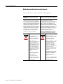
Understand Product
Compatibilty
The 1771-IFF module can be used with any 1771 I/O chassis. Compatibility
and data table usage is listed below.
Catalog
Number
1771-IFF/A
Use of Data Table
Compatibility
Image
Input
Bits
Output Read Write Addressing
Image Block Block
1/2- Slot 1-Slot
Bits
Words Words
8
8
24
41
Y
Y
2-Slot
Y
Chassis
Series
A, B
A = Compatible with 1771-A1, -A2, -A4
B = Compatible with 1771-A1B, -A2B, -A3B, -A3B1, -A4B
Y = Compatible without restriction
ATTENTION
Do not use this module with Cat. No. 1771-AL PLC-2/20
or 2/30 Local Adapter.
Publication 1771-IN046B-EN-P - December 2003
6
Fast Analog Input Module
Calculate Power
Requirements
The module receives its power through the 1771 I/O power supply and
requires 500mA from the backplane.
Add this current to the requirements of all other modules in the I/O chassis to
prevent overloading the chassis backplane and/or backplane power supply.
ATTENTION
Determine Module
Placement in the I/O
Chassis
Do not insert or remove modules from the I/O chassis
while system power is ON. Failure to observe this rule
could result in damage to the module circuitry.
Place your module in any slot of the chassis except for the extreme left slot.
This slot is reserved for PC processors or adapter modules.
Group your modules to minimize adverse affects from radiated electrical noise
and heat. We recommend the following:
• Group analog input and low voltage dc modules away from ac modules
or high voltage dc modules to minimize electrical noise interference.
• Do not place this module in the same I/O group with a digital
high-density I/O module when using 2-slot addressing. This module
uses a byte in both the input and output image tables for block transfer.
The 1771-IFF is a modular component of the 1771 I/O system requiring a
properly installed system chassis. Refer to publication 1771-IN075 for detailed
information on acceptable chassis, proper installation and grounding
requirements. Limit the maximum adjacent slot power dissipation to 10W
or less.
Publication 1771-IN046B-EN-P - December 2003
Fast Analog Input Module
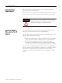
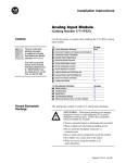
Set the Simulation Jumper
7
The module is shipped with the simulation jumper set in position POS G. This
setting allows input data to go above and below the range points. If the
simulation jumper is set to the POS E position, input data is clamped (does
not exceed) at range end points.
Simulation
Set the Simulation Jumper
Top edge of circuit board
Jumper
POS G
1. Locate the simulation jumper at the top edge
of the module circuit board.
POS E
Simulation
Simulation Jumper (shown in POS E
position). This position provides Clamped
Input Data at range end points.
2. Using your fingers, slide the jumper of f the 2 posts.
3. Carefully position the jumper on 2 of the 3 posts that
correspond to your requirement.
Top edge of circuit board
POS G
POS E
Simulation Jumper (shown in POS G
position). This position does not Clamp Input
Data at range end points.
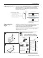
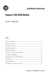
The module has configuration jumpers for determining the input type (voltage
or current) desired for each input. The module is shipped with the
configuration jumpers positioned for voltage mode.
Set the Configuration
Jumpers
Not that you can select either voltage or current for each input, but they must
all be either single-ended or all differential. Do not mix single-ended or
differential inputs on the module.
1
Remove the four screws securing the side
cover to the module and remove the covers.
12
Reposition the configuration jumpers associated with each
input channel according to your requirements
Y ou can mix voltage mode and current mode
settings on the module. Make sure that the entire
module is set for either single-ended or dif ferential.
Do not mix them.
Voltage Mode
Differential or Single-ended (factory set)
19805
13
Reposition the cover and secure with the four
screws removed in step 1.
Current Mode
Single-ended
Differential
Current
Current
Single-ended
Odd channel current
Even channel voltage
Even channel current
19813
Configuration
Jumpers
Single-ended Differential
Channel Channel 1
1 and 2
Channel Channel 2
3 and 4
Channel Channel 3
5 and 6
Channel Channel 4
7 and 8
Channel
Channel 5
9 and 10
Channel
Channel 6
11 and 12
Channel
Channel 7
13 and 14
Channel
Channel 8
15 and 16
Odd channel voltage
Publication 1771-IN046B-EN-P - December 2003
8
Fast Analog Input Module
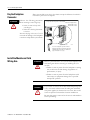
Key the Backplane
Connector
ATTENTION
Place your module in any slot in the chassis except the leftmost slot which is
reserved for processors or adapters.
Observe the following precautions
when inserting or removing keys:
• insert or remove keys with
your fingers
• make sure that key placement
is correct
Incorrect keying or the use of a tool
can result in damage to the backplane
connector and possible system faults.
Position the keying bands in the backplane connectors to
correspond to the key slots on the module.
Place the keying bands:
between 10 and 12
between 24 and 26
I/O chassis
Upper Connector
11022-I
Y ou can change the position of these
bands if subsequent system design and
rewiring makes insertion of a dif ferent
type of module necessary.
Install the Module and Field
Wiring Arm
ATTENTION
Remove power from the 1771 I/O chassis backplane and
field wiring arm before removing or installing the I/O
module.
• Failure to remove power from the backplane or wiring
arm could cause module damage, degradation of
performance, or injury.
• Failure to remove power from the backplane could
cause injury or equipment damage due to possible
unexpected operation.
WARNING
If you insert or remove the module while backplane power
is on, or connect or disconnect the wiring arm with field
side power applied, an electrical arc can occur. This could
cause an explosion in hazardous location installations.
Be sure that power is removed or the area is nonhazardous
before proceeding.
Publication 1771-IN046B-EN-P - December 2003
Fast Analog Input Module
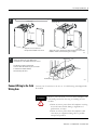
1
1771-A1B, -A2B, -A3B, -A3B1, -A4B I/O chassis
9
1771-A1B, -A2B, -A3B1, -A4B Series B I/O chassis
locking tab
locking bar
locking bar pin
card guides
card guides
IFF module
Snap the chassis latch over
the top of the module to secure it.
IFF module
Swing the chassis locking bar down into place to secure the
modules. Make sure the locking pins engage.
19809
2
wiring arm
Attach the wiring arm (1771-WG) to the
horizontal bar at the bottom of the I/O chassis.
The wiring arm pivots upward and
connects with the module so you can install
or remove the module without
disconnecting the wires.
1771-WG
remove
horizontal bar
Connect Wiring to the Field
Wiring Arm
install
17643
Connect your I/O devices to the cat. no. 1771-WG wiring arm shipped with
the module
ATTENTION
Remove power from the 1771 I/O chassis backplane and
field wiring arm before removing or installing the I/O
module.
• Failure to remove power from the backplane or wiring
arm could cause module damage, degradation of
performance, or injury.
• Failure to remove power from the backplane could
cause injury or equipment damage due to possible
unexpected operation.
Publication 1771-IN046B-EN-P - December 2003
10
Fast Analog Input Module
WARNING
If you connect or disconnect the wiring with field-side
power applied, an electrical arc can occur. This could cause
an explosion in hazardous location installations.
Be sure that power is removed or the area is nonhazardous
before proceeding.
Input connections for the 1771-IFF with:
• single-ended inputs are shown on page 11.
• differential inputs are shown on page 12.
Minimizing Ground Loops
To minimize ground loop current on input circuits:
•
•
•
•
use single-ended mode whenever possible
use 2-wire transmitters with a common power supply
separate 2-wire and 4-wire transmitters between different modules
tie 4-wire transmitter and/or separate power supply grounds together
IMPORTANT
Mixing 2-wire and 4-wire transmitter inputs on the same
module is not recommended. Power supply placement can
make it impossible to eliminate ground loops.
Cable Lengths
Recommended maximum cable length for voltage-mode input devices is 50
feet (15.24m), due to possible signal degradation and electrical noise immunity
in typical industrial environments. Cable length for current-mode input devices
need not be as restrictive because analog signals from these devices are less
sensistive to electrical noise interference.
Publication 1771-IN046B-EN-P - December 2003
Fast Analog Input Module
11
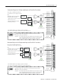
single-ended wiring
Connection Diagram for 16 Single-ended Inputs and Two-Wire Transmitters
Note: Refer to transmitter manufacturers
specifications for power supply connections.
Note:
+
2-Wire
Transmitter
– All module commons are electrically
tied together inside the module.
Power
Supply
– Jumper all unused channels to module
common to reduce noise.
–
2-Wire
Transmitter
– Tie power supply grounds together
to minimize ground loops.
+
_
Power
Supply
Functional Ground
The 1771-IFF module does not supply loop power for the input
device. The user must supply loop power for loop-powered input devices.
The sensor cable must be shielded. The shield must:
extend the length of the cable, but be connected only at the 1771 I/O chassis
extend up to the point of termination
Important:
The shield should extend to the termination point, exposing just enough
cable to adequately terminate the inner conductors. Use heat shrink or
another suitable insulation where the wire exits the cable jacket.
Channel 1
Channel 2
Channel 3
Channel 4
Module Common
Channel 5
Channel 6
Channel 7
Channel 8
Module Common
Channel 9
Channel 10
Channel 1 1
Channel 12
Module Common
Channel 13
Channel 14
Channel 15
Channel 16
Module Common
Module Common
1
2
3
4
5
6
7
8
9
10
11
12
13
14
15
16
17
18
19
20
21
1771-WG
Field Wiring Arm
Connection Diagram for 16 Single-ended Inputs and Four-Wire Transmitters
Note: Refer to transmitter manufacturers
specifications for power supply connections.
Note:
– All module commons are electrically Power
Supply
tied together inside the module.
4-Wire
Transmitter
+
–
– Jumper all unused channels to module
common to reduce noise.
– Tie power supply grounds together
to minimize ground loops.
Power
Supply
4-Wire
Transmitter
+
_
Functional Ground
The 1771-IFF module does not supply loop power for the input
device. The user must supply loop power for loop-powered input devices.
The sensor cable must be shielded. The shield must:
extend the length of the cable, but be connected only at the 1771 I/O chassis
extend up to the point of termination
Important:
Channel 1
Channel 2
Channel 3
Channel 4
Module Common
Channel 5
Channel 6
Channel 7
Channel 8
Module Common
Channel 9
Channel 10
Channel 1 1
Channel 12
Module Common
Channel 13
Channel 14
Channel 15
Channel 16
Module Common
Module Common
1
2
3
4
5
6
7
8
9
10
11
12
13
14
15
16
17
18
19
20
21
1771-WG
Field Wiring Arm
The shield should extend to the termination point, exposing just enough
cable to adequately terminate the inner conductors. Use heat shrink or
another suitable insulation where the wire exits the cable jacket.
Publication 1771-IN046B-EN-P - December 2003
12
Fast Analog Input Module
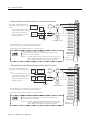
differential wiring
Connection Diagram for 8 Differential Inputs and Two-Wire Transmitters
Note: Refer to transmitter manufacturers
specifications for power supply connections.
Note:
– Unused channels must have their + and
- inputs jumpered together and tied to
module common to reduce noise.
–
Tie power supply grounds together to
minimize ground loops.
+
2-Wire
Transmitter
Power
Supply
2-Wire
Transmitter
–
+
–
Power
Supply
Functional Ground
The 1771-IFF module does not supply loop power for the input device.
The user must supply loop power for loop-powered input devices.
Configuring the module for differential inputs does not provide isolation.
The sensor cable must be shielded. The shield must:
extend the length of the cable, but be connected only at the 1771 I/O chassis
extend up to the point of termination
Important:
The shield should extend to the termination point, exposing just enough
cable to adequately terminate the inner conductors. Use heat shrink or
another suitable insulation where the wire exits the cable jacket.
Channel 1+
Channel 1Channel 2+
Channel 2Not used
Channel 3+
Channel 3Channel 4+
Channel 4Not used
Channel 5+
Channel 5Channel 6+
Channel 6Not used
Channel 7+
Channel 7Channel 8+
Channel 8Module Common
Module Common
1
2
3
4
5
6
7
8
9
10
11
12
13
14
15
16
17
18
19
20
21
1771-WG
Field W iring Arm
Connection Diagram for 8 Differential Inputs and Four-Wire Transmitters
Note: Refer to transmitter manufacturers
specifications for power supply connections.
Note:
– Unused channels must havetheir + and
- inputs jumpered together and tied to
module common to reduce noise.
–
Tie power supply grounds together to
minimize ground loops.
Power
Supply
4-Wire
Transmitter
Power
Supply
4-Wire
Transmitter
+
–
+
–
Functional Ground
The 1771-IFF module does not supply loop power for the input device.
The user must supply loop power for loop-powered input devices.
Configuring the module for differential inputs does not provide isolation.
The sensor cable must be shielded. The shield must:
extend the length of the cable, but be connected only at the 1771 I/O chassis
extend up to the point of termination
Important:
The shield should extend to the termination point, exposing just enough
cable to adequately terminate the inner conductors. Use heat shrink or
another suitable insulation where the wire exits the cable jacket.
Publication 1771-IN046B-EN-P - December 2003
Channel 1+
Channel 1Channel 2+
Channel 2Not used
Channel 3+
Channel 3Channel 4+
Channel 4Not used
Channel 5+
Channel 5Channel 6+
Channel 6Not used
Channel 7+
Channel 7Channel 8+
Channel 8Module Common
Module Common
1771-WG
Field Wiring Arm
1
2
3
4
5
6
7
8
9
10
11
12
13
14
15
16
17
18
19
20
21
Fast Analog Input Module
When using shielded cable wire, ground the foil shield and drain wire only at
one end of the cable. We recommend that you wrap the foil shield and drain
together, and connect them to a chassis mounting bolt, grounding stud or
chassis single-point grounding point. Use heat-shrink tubing to seal the exit
point of the wires. At the opposite end of the cable, tape exposed shield and
drain wire with electrical tape to insulate it from electrical contact.
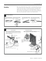
Grounding
1
Cable Grounding
Remove a length of cable Pull the foil shield and bare
jacket from the Belden 8761 drain wire from the insulated
cable.
wires.
Bare drain
wire
Belden 8761 Cable
Twist the foil shield and drain Attach a ground lug, and apply
wire together to form a single heat shrink tubing to the exit area.
strand.
Length as needed
Insulated
wires
Foil
shield
2
13
20104
Chassis Ground
When you connect grounding conductors to the I/O
chassis grounding stud, place a star washer under the
first lug, then place a nut with captive lock washer on
top of each ground lug.
Single-point Grounding
Extend shield to termination point. Expose just enough
cable to adequately terminate inner conductors.
Ground Lug
Nut
Nut and Captive
Washer
Use heat shrink tubing or
other suitable insulation
where wire exits cable
jacket.
Grounding Stud
Star
Washer
I/O Chassis
Side Plate
Ground Lug 1
Shield and Drain
twisted together
1 Use the cup washer if crimp-on lugs are not used.
19480
Shield and Drain
twisted together
#10 Thread-forming screw
External-tooth
Washers
19923
Publication 1771-IN046B-EN-P - December 2003
14
Fast Analog Input Module
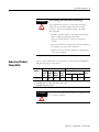
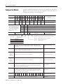
You must configure the module to conform to the analog device and specific
application that you have chosen. Use the configuration information below to
configure your module to your specifications.
Configure the Module
Dec. Bits
15
14
13
1
2
11
1
0
0
9
08
07
06
05
04
03
02
01
00
Octal Bits
17
16
15
1
4
13
1
2
11
10
07
06
05
04
03
02
01
00
Description
Word 1
8
7
6
5
4
3
2
1
Range Selection - Channels 1 - 8
2
16
15
14
13
12
11
10
9
Range Selection - Channels 9-16
Input
p rangegselections allow the
user to configure the inputs for
any of 7 input voltage or current
ranges. Two bits are required for
for each channel. Bits 00 and 01 for
channel 1, bits 02 and 03 for
channel 2, etc.
3
Bit 01
Bit 00
Voltage or Current Input
0
0
1 to 5V dc, 4 to 20mA (default)
0
1
0 to 5V dc, 0 to 20mA
1
0
-5 to +5V dc, -20 to +20mA
1
1
-10 to +10V dc, 0 to 10V dc
Data
Format
Real Time Sampling
Input
Type
Real time sampling, data format,
input type and digital filter
Digital Filter
Real time sampling - Default is no RTS
0
0
BCD(default)
0
1
1
2' s Complement, data first
Two' s complement binary
1
0
1
Digital filter reduces ef fect of noise on input. (Default is no filter.)
Data format - set to
match your processor .
Bit 10 Bit09
(12) (11)
Input type , set bit for differential mode on all channels.
Reset (0) = single-ended inputs (default)
Set (1)
= differential inputs
Signed magnitude binary
4
Minimum sign bits , when set, designate negative minimum scaling values for the
corresponding input channels. Bit 00 corresponds to channel 1, bit 01 corresponds to
channel 2, etc.
Sign Bits, minimum scaling
values
5
Maximum sign bits, when set, designate maximum scaling values that are negative.
Maximum scaling value must be greater than minimum on any particular channel. Bit 00
corresponds to channel 1, bit 01 corresponds to channel 2, etc.
Sign Bits, maximum scaling
values
6, 8, 10, 12,
14, 16, 18,
20, 22, 24,
26, 28, 30,
32, 34, 36
Minimum scaling values for each channel. Enter in BCD format.
Channel 1 - minimum scaling
7, 9, 1 1, 13,
15, 17, 19,
21, 23, 25,
27, 29, 31,
33, 35, 37
Maximum scaling values for each channel. Enter in BCD format.
Channel 1 - maximum scaling
38
Offset calibration - Each bit represents a channel (bit 00 to channel 1, bit 02 to channel 2,
etc.). When the bit is set, and a BTW has been sent, the module will read the channels and
adjust the offset to analog ground potential. In differential mode, bits 08 thru 15 (10 thru 17
in octal) are ignored. In current mode, apply 0mA.
Of fset Calibration
39
Gain calibration - Each bit represents a channel (bit 00 to channel 1, bit 02 to channel 2, etc).
When the bit is set, and a BTW has been sent, the module will read the channels and adjust
the gain correction values. If used on +, 0 to 5, or 1 to 5V ranges, a value of 5V is expected.
If used on +10V range, 10V is expected. In dif ferential mode, bits 08 thru 15 (10 thru 17 in
octal) are ignored. In current mode, apply 20mA.
Gain Calibration
40
15
41
14
13
12
11
10
9
8
7
6
5
4
BCD or binary , 0-256 (2 X only), 0 = default (8X oversample)
Publication 1771-IN046B-EN-P - December 2003
3
2
1
0
Channel Sampling Disable
Oversampling
Fast Analog Input Module
15
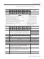
Use the following table to read data from your input module.
Dec. Bits
15
14
13
12
11
10
09
08
07
06
05
04
03
02
01
00
Octal Bits
17
16
15
14
13
12
11
10
07
06
05
04
03
02
01
00
HF
EE
CS RTS
IS
OR
PU
Word 1
Hardware fault - (HF) When this bit is set, the
dc/dc converter fuse has blown. Digital logic will
continue to operate.
EEPROM status bit - (EE) This bit is set if an error occurs
saving calibration data to nonvolatile memory . If this bit is
set at powerup, the data from the EEPROM did not pass the
checksum and no calibration values are used.
Calibration status bit - (CS) When calibrating the module,
this bit will be cleared if the calibration was successful. If the
bit is set, an incorrect voltage/current was applied, or
.
offset and gain calibrations were attempted simultaneously
3
Out of range bit - (OR) This bit is sent
to tell the processor that one or more
channels are either over or under range.
Invalid scaling bit - (IS) This bit reports
that the scaling is somehow invalid. Usually
both values are equal or minimum is greater
than maximum when this bit comes on. Can
also be an invalid filter value.
,
16 15
14
13
12
11
10
9
8
7
6
5
4
3
2
1
Data underrange for channels
1-16
16
14
13
12
11
10
9
8
7
6
5
4
3
2
1
Data overrange for channels
1-16
15
Underrange bits
b t s for eachchannel
each channel. Bit 00 for channel 11, bit 01 for channel 22, etc
etc.
These bits are set (1) at approximately the input range limits shown on the right.
Overrange bits for each channel. Bit 00 for channel 1, bit 01 for channel 2, etc.
These bits are set (1) at approximately the input range limits shown on the right.
4
Diagnostics
Power up bit - (PU) Used by the
module to tell the processor that it is
alive but not yet configured. It is a key
element in the application program.
Real time sample fault bit - (R TS) This bit is set if the module
is configured for R TS and a block transfer read has not occurred
within the user±programmed period.
2
Description
16
15
14
13
12
11
10
9
8
7
6
5
4
3
2
1 to 5V dc, 4 to 20mA (default)
0 to 5V dc, 0 to 20mA
-5 to +5V dc, -20 to +20mA
-10 to +10V dc, 0 to 10V dc
1
Data polarity for channels 1-16
Polarity bits - Set when input is less than zero. Bit 00 for channel 1, bit 01 for
channel 2, etc.
5
Channel 1 Input
Channel 1 Input
6
Channel 2 Input
Channel 2 Input
7
Channel 3 Input
Channel 3 Input
8
Channel 4 Input
Channel 4 Input
⇓
⇓
⇓
⇓
20
Channel 16 Input
Channel 16 Input
21
Offset calibration results bits - Each bit represents a channel. After a
calibration BTW has been sent, the module confirms calibration by echoing back
the channels that were calibrated during the offset calibration BTW . In
differential mode, channels 09 thru 16 are zero.
Of fset Calibration Results
22
Gain calibration results bits - Each bit represents a channel. After a calibration
BTW has been sent, the module confirms calibration by echoing back the
channels that were calibrated during the gain calibration BTW. In differential
mode, channels 09 thru 16 are zero.
Gain Calibration Results
23
binary, 1ms resolution
Time Stamp
24
10 ms resolution
Scan time
Publication 1771-IN046B-EN-P - December 2003
16
Fast Analog Input Module
When Data Format bits 9 and 10 in block transfer write word 3 are set for “2’s
complement - data first,” the block transfer read will transmit channel data first
in the transfer. For single-ended configuration, words 1 through 16 will have
channel data. For differential configuration, words 1 through 8 will contain
channel data.
Default Configuration
If a write block of five words with all zeroes is sent to the module, default
selections will be:
•
•
•
•
•
•
•
Interpret Status Indicators
1 to 5V dc or 4 to 20mA (dependent on configuration jumper setting)
BCD data format
no real time sampling (RTS)
no filtering
single-ended inputs
8X oversample
oversample enabled on all channels
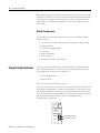
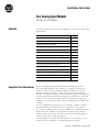
The front panel of the analog input module contains a green RUN indicator
and a red FAULT indicator. At power-up, the module momentarily turns on
the red indicator as a lamp test, then checks for:
• correct RAM operation
• firmware errors
If there is no fault, the red indicator goes off.
The green indicator comes on when the module is powered. It will flash until
the module is programmed. If a fault is found initially or occurs later, the red
fault indicator lights. The module also reports status and specific faults (if they
occur) in every transfer of data (BTR) to the PC processor. Monitor the green
and red indicators and status bits in word 1 of the BTR file when
troubleshooting your module.
FAST
ANALOG
(12 BIT)
RUN
FL T
Publication 1771-IN046B-EN-P - December 2003
Green RUN indicator
Red F AULT indicator
Fast Analog Input Module
Troubleshooting
17
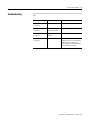
Possible module fault causes and corrective action is described in the following
table.
Indicators
Probable Cause
Recommended Action
RUN (green on)
Normal operation
None
Awaiting configuration
block transfer write
Send configuration BTW
Return module for repair
FLT (red on)
Hardware failure in
module
RUN (green off)
No power
Turn off power. Remove and reinsert
module into chassis. Return power. If
problem still exists, and chassis
power supply is functioning properly,
return the module for repair.
FLT (red off)
RUN (green blinking)
FLT (red off)
RUN (green off)
FLT (red off)
Publication 1771-IN046B-EN-P - December 2003
18
Fast Analog Input Module
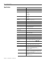
Specifications
Description
Value
Inputs per module
16 single-ended; 8 differential low level
Module Location
1771 I/O chassis - 1 slot
Input Voltage Ranges (nominal)
+1 to +5V dc
0 to +5V dc
-5 to +5V dc
-10 to +10V dc
0 to +10V dc
Input Current Ranges (nominal)
+4 to +20mA
0 to 20mA
-20 to +20mA
Resolution
12-bit binary
12 bits plus sign on bipolar ranges
Accuracy
1.0% of full scale range at 25°C
Linearity
+1 LSB
Repeatability
+1 LSB
Isolation Voltage
Tested to 850V dc for 1s
Input overvoltage protection
35V maximum (voltage mode)
8V maximum (current mode)
Input overcurrent protection
(current ranges)
30mA
Common mode voltage
+35V
Input impedance
>10 megohms (voltage ranges)
250 ohms (current ranges)
Common mode rejection
80db, dc - 120Hz
Current requirements
500mA at 5V dc from I/O chassis backplane
Power dissipation
Backplane: 2.5W maximum; Inputs: 2.5W maximum
Thermal dissipation
17 BTU/hr maximum
Unscaled BCD and binary output
to processor
0000 to 4095 for polar ranges (0-5V, 1-5V 0-20mA, and 4-20mA)
-409510 to +409510 for bipolar ranges (+5V, +10V,+ 20mA)
Engineering units sent to
processor
+999910 with selectable scaling
Fastest internal scan rate
8 channels in less than 2ms (depending on number of
oversamples, number of channels, and active features)
Environmental Conditions
Publication 1771-IN046B-EN-P - December 2003
Operational Temperature
IEC 60068-2-1 (Test Ad, Operating Cold),
IEC 60068-2-2 (Test Bd, Operating Dry Heat),
IEC 60068-2-14 (Test Nb, Operating Thermal Shock):
0 to 60°C (32 to 140°F)
Storage Temperature
IEC 60068-2-1 (Test Ab, Unpackaged Nonoperating Cold),
IEC 60068-2-2 (Test Bb, Unpackaged Nonoperating Dry Heat),
IEC 60068-2-14 (Test Na, Unpackaged Nonoperating Thermal
Shock): -40 to 85°C (-40 to 185°F)
Relative Humidity
IEC 60068-2-30 (Test Db, Unpackaged Nonoperating
Damp Heat):
5 to 95% noncondensing
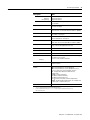
Fast Analog Input Module
Description
19
Value
Shock
Operating
Non-operating
Vibration
IEC 60068-2-27 (Test Ea, Unpackaged Shock)
30g peak acceleration
50g peak acceleration
IEC 60068-2-6, (Test Fc, Operating)
2g @ 10-500Hz
ESD Immunity
IEC 61000-4-2:
4kV contact discharges
Radiated RF Immunity
IEC 61000-4-3:
10V/m with 1kHz sine-wave 80%AM from 30MHz to 1000MHz
EFT/B Immunity
IEC 61000-4-4:
±1kV at 5kHz on signal ports
Surge Transient Immunity
IEC 61000-4-5:
±2kV line-earth(CM) on shielded ports
Conducted RF Immunity
IEC 61000-4-6:
10Vrms with 1kHz sine-wave 80%AM from 150kHz to 30MHz
Emissions
CISPR 11
Group 1, Class A (with appropriate enclosure)
Enclosure Type Rating
None (open-style)
Field Wiring Arm
Cat. No. 1771-WG
Field Wiring Arm Screw Torque
9 pound-inches (1.0Nm)
Conductors Wire Size
14 AWG (2.5mm2) - 22 AWG (0.25mm2) solid or stranded copper
wire rated at 75°C or greater
3/64 inch (1.2mm) insulation maximum
21
Category
Keying
between 10 and 12
between 24 and 26
Certifications (when product is
marked)
UL - UL Listed Industrial Control Equipment
CSA - CSA Certified Process Control Equipment
CSA - CSA Certified Process Control Equipment for Class I,
Division 2, Groups A, B, C and D Hazardous locations
CE2 - European Union 89/336/EEC EMC Directive,
compliant with:
EN 50082-2; Industrial Immunity
EN 61000-6-2; Industrial Immunity
EN 61000-6-4; Industrial Emissions
EN 61326; Meas./Control/Lab., Industrial Requirements
C-Tick2 - Australian Radiocommunications Act compliant with
AS/NZS CISPR 11, Industrial Emissions
User Manual
Publication 1771-6.5.116
1
2
Use this conductor category information for planning conductor routing as described in publication
1770-4.1, “Industrial Automation Wiring and Grounding Guidelines.”
See the Product Certification link at www.ab.com for Declaration of Conformity, Certificates, and
other certification details.
Publication 1771-IN046B-EN-P - December 2003
Rockwell Automation Support
Rockwell Automation provides technical information on the web to assist you in using our products. At
http://support.rockwellautomation.com, you can find technical manuals, a knowledge base of FAQs, technical and
application notes, sample code and links to software service packs, and a MySupport feature that you can customize
to make the best use of these tools.
For an additional level of technical phone support for installation, configuration and troubleshooting, we offer
TechConnect Support programs. For more information, contact your local distributor or Rockwell Automation
representative, or visit http://support.rockwellautomation.com.
Installation Assistance
If you experience a problem with a hardware module within the first 24 hours of installation, please review the
information that's contained in this manual. You can also contact a special Customer Support number for initial help
in getting your module up and running:
United States
1.440.646.3223
Monday – Friday, 8am – 5pm EST
Outside United States
Please contact your local Rockwell Automation representative for any technical support issues.
New Product Satisfaction Return
Rockwell tests all of our products to ensure that they are fully operational when shipped from the manufacturing
facility. However, if your product is not functioning and needs to be returned:
United States
Contact your distributor. You must provide a Customer Support case number (see phone number
above to obtain one) to your distributor in order to complete the return process.
Outside United States
Please contact your local Rockwell Automation representative for return procedure.
Publication 1771-IN046B-EN-P - December 2003 20
Supersedes Publication 1771-5.46 - May 1996
PN 957859-99
Copyright © 2003 Rockwell Automation, Inc. All rights reserved. Printed in the U.S.A.