1
ControlNet PLC-5
Programmable
Controllers
Catalog Numbers 1785-L20C15,
-L40C15, -L46C15, -L80C15
Quick Start
Important User Information
Because of the variety of uses for the products described in this
publication, those responsible for the application and use of these
products must satisfy themselves that all necessary steps have been
taken to assure that each application and use meets all performance
and safety requirements, including any applicable laws, regulations,
codes and standards. In no event will Allen-Bradley be responsible or
liable for indirect or consequential damage resulting from the use or
application of these products.
Any illustrations, charts, sample programs, and layout examples
shown in this publication are intended solely for purposes of
example. Since there are many variables and requirements associated
with any particular installation, Allen-Bradley does not assume
responsibility or liability (to include intellectual property liability) for
actual use based upon the examples shown in this publication.
Allen-Bradley publication SGI-1.1, Safety Guidelines for the
Application, Installation and Maintenance of Solid-State Control
(available from your local Allen-Bradley office), describes some
important differences between solid-state equipment and
electromechanical devices that should be taken into consideration
when applying products such as those described in this publication.
Reproduction of the contents of this copyrighted publication, in whole
or part, without written permission of Rockwell Automation, is
prohibited.
Throughout this publication, notes may be used to make you aware of
safety considerations. The following annotations and their
accompanying statements help you to identify a potential hazard,
avoid a potential hazard, and recognize the consequences of a
potential hazard:
WARNING
!
ATTENTION
!
IMPORTANT
Identifies information about practices or
circumstances that can cause an explosion in a
hazardous environment, which may lead to personal
injury or death, property damage, or economic loss.
Identifies information about practices or
circumstances that can lead to personal injury or
death, property damage, or economic loss.
Identifies information that is critical for successful
application and understanding of the product.
ATTENTION
!
Environment and Enclosure
This equipment is intended for use in a Pollution
Degree 2 industrial environment, in overvoltage
Category II applications (as defined in IEC
publication 60664-1), at altitudes up to 2000 meters
without derating.
This equipment is considered Group 1, Class A
industrial equipment according to IEC/CISPR
Publication 11. Without appropriate precautions,
there may be potential difficulties ensuring
electromagnetic compatibility in other
environments due to conducted as well as radiated
disturbance.
This equipment is supplied as "open type"
equipment. It must be mounted within an enclosure
that is suitably designed for those specific
environmental conditions that will be present and
appropriately designed to prevent personal injury
resulting from accessibility to live parts. The
interior of the enclosure must be accessible only by
the use of a tool. Subsequent sections of this
publication may contain additional information
regarding specific enclosure type ratings that are
required to comply with certain product safety
certifications.
See NEMA Standards publication 250 and IEC
publication 60529, as applicable, for explanations
of the degrees of protection provided by different
types of enclosure. Also, see the appropriate
sections in this publication, as well as the
Allen-Bradley publication 1770-4.1 ("Industrial
Automation Wiring and Grounding Guidelines"),
for additional installation requirements pertaining to
this equipment.
Ethernet is a registered trademark of Intel Corporation, Xerox Corporation, and Digital Equipment Corporation.
ControlNet is a trademark of ControlNet International.
Allen-Bradley, PLC, PLC-2, PLC-3 and PLC-5 are registered trademarks of Rockwell Automation, Inc.
Data Highway Plus, DH+, RSLinx, RSLogix, RSNetWorx, RSNetworx for ControlNet, FLEX I/O , PLC-5/11, -5/20,
-5/20C, -5/26, -5/30, -5/40, -5/46, -5/40L, -5/40C, -5/60, -5/60L, -5/80, -5/80C, -5/86, -5/20E, -5/40E, and -5/80E are
trademarks of Rockwell Automation, Inc.
Rockwell Automation
Support
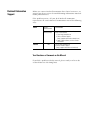
Before you contact Rockwell Automation for technical assistance, we
suggest you please review the troubleshooting information contained
in this publication first.
If the problem persists, call your local Rockwell Automation
representative or contact Rockwell Automation in one of the following
ways:
Phone
Internet
United
States/Canada
1.440.646.5800
Outside United
States/Canada
You can access the phone number for your
country via the Internet:
1. Go to http://www.ab.com
2. Click on Product Support
(http://support.automation.rockwell.com)
3. Under Support Centers, click on Contact
Information
⇒
1. Go to http://www.ab.com
2. Click on Product Support
(http://support.automation.rockwell.com)
Your Questions or Comments on this Manual
If you find a problem with this manual, please notify us of it on the
enclosed How Are We Doing form.
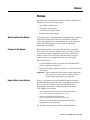
Preface
Preface
Read this preface to familiarize yourself with the rest of the manual.
This preface covers the following topics:
•
who should use this manual
•
the purpose of this manual
•
conventions used in this manual
•
Rockwell Automation support
Who Should Use this Manual
To use this manual, you should understand programmable controllers
and be able to interpret the ladder logic instructions required to
control your application. For more information, see the documents
listed on the following page or contact your local Rockwell
Automation representative.
Purpose of this Manual
This manual introduces you to installing and using a ControlNet
PLC-5 processor system. In addition, it shows you how to set up a
system using a typical configuration. Since this is a Quick Start
manual, we do not cover all of the ControlNet PLC-5 processor
features, but give you enough information to get you started.
This manual includes:
•
basic information needed to start using the ControlNet PLC-5
processor quickly and effectively
•
high-level procedures with cross-references to other manuals for
more details
Important: The recommended switch settings in this manual help
you set up a test system and get it working. Actual
switch settings depend upon your application.
How to Obtain a User Manual
There is a user manual associated with this product that contains
detailed information about configuring, programming, and using a
PLC-5 processor. To obtain a copy of the ControlNet PLC-5
Programmable Controllers User Manual, publication number
1785-UM022, you can either:
•
view or download an electronic version from the internet:
www.theautomationbookstore.com
•
purchase a hardcopy from the internet:
www.theautomationbookstore.com
•
contact your local distributor or Rockwell Automation
representative to place an order.
See the table on the next page for other related publications.
Publication 1785-QS006C-EN-P - April 2002
P-6
Preface
Related Documentation
The following documents contain additional information concerning
the products discussed in this manual.
For more information about:
See this publication:
Publication number:
ControlNet PLC-5 programmable
controllers (1785-L20C15, -L40C15,
-L46C15 and -L80C15)
ControlNet PLC-5 Programmable Controllers User Manual
1785-UM022
Enhanced and Ethernet PLC-5 Programmable Controllers User Manual
1785-6.5.12
1785 Enhanced PLC-5 Processor System Overview
1785-2.36
ControlNet System Overview
CNET-SO001
1785 PLC-5 Programmable Controllers Quick Reference
1785-7.1
PLC-5 Programming Software Instruction Set Reference Manual
1785-6.1
Industrial Automation Wiring and Grounding Guidelines
1770-4.1
ControlNet Cable System Component List
AG-2.2
ControlNet Cable System Planning and Installation Manual
1786-6.2.1
ControlNet Fiber Planning Installation Guide
CNET-IN001
ControlNet Network Access Cable Installation Instructions
1786-2.6
Universal 1771 I/O chassis
Universal I/O Chassis installation instructions
1771-2.210
power supplies
Power Supply Modules (1771-P4S, -P6S, -P4S1, -P6S1) Installation Data
Redundant Power Supply Modules (1771-P4R, -P64) Installation Instruction
AC Power Supply (1771-P7) Installation Instructions
1771-2.135
1771-5.30
1771-IN056
handling lithium batteries
Guidelines for Handling Lithium Batteries
AG-5.4
DH+ network
Enhanced and Ethernet Programmable Controllers User Manual
1785-6.5.12
Data Highway/Data Highway Plus/Data Highway II/Data Highway-485 Cable
installation instructions
1770-6.2.2
communication card (1784-KTCx15)
ControlNet Communication Interface Card installation instructions
1784-5.20
communication interface
(1770-KFC15)
ControlNet Communication Interface User Manual
1770-6.5.20
terms and definitions
Industrial Automation Glossary
AG-7.1
ControlNet media
Publication 1785-QS006C-EN-P - April 2002
Preface
Conventions Used in This
Manual
P-7
The following conventions are used throughout this manual:
•
Bulleted lists provide information, not procedural steps.
•
Numbered lists provide sequential steps or hierarchical
information.
•
Italic type is used for emphasis.
•
Text in this font indicates words or phrases you should type.
•
Key names match the names shown and appear in bold, capital
letters (for example, ENTER).
Tip: We use this convention to call attention to helpful information.
Publication 1785-QS006C-EN-P - April 2002
P-8
Preface
Notes
Publication 1785-QS006C-EN-P - April 2002
Table of Contents
Before You Begin
Set Up the Hardware
Set Up the Software
Troubleshoot the Processor
System
Specifications
Chapter 1
What You Need to Do . . . . . . . . . . . . . . . . . . . . . . . . . . . . . . . . . . . . . . 1-1
Identify the Processor’s Front Panel Components. . . . . . . . . . . . . . . 1-2
Check Your Components. . . . . . . . . . . . . . . . . . . . . . . . . . . . . . . . . . . . 1-3
Compliance to European Union Directives . . . . . . . . . . . . . . . . . . . . . . 1-4
EMC Directive. . . . . . . . . . . . . . . . . . . . . . . . . . . . . . . . . . . . . . . . . . 1-4
Low Voltage Directive . . . . . . . . . . . . . . . . . . . . . . . . . . . . . . . . . . . 1-4
Chapter 2
Install the Hardware. . . . . . . . . . . . . . . . . . . . . . . . . . . . . . . . . . . . . . . . 2-2
Configure the I/O Chassis . . . . . . . . . . . . . . . . . . . . . . . . . . . . . . . . . 2-2
Ground the I/O Chassis . . . . . . . . . . . . . . . . . . . . . . . . . . . . . . . . . . . 2-3
Install the Power Supply . . . . . . . . . . . . . . . . . . . . . . . . . . . . . . . . . . 2-4
Install the PLC-5 Processor . . . . . . . . . . . . . . . . . . . . . . . . . . . . . . . . 2-5
Powerup the System . . . . . . . . . . . . . . . . . . . . . . . . . . . . . . . . . . . . . 2-6
Install the I/O Modules . . . . . . . . . . . . . . . . . . . . . . . . . . . . . . . . . . . 2-6
Connect the Personal Computer to the PLC-5 Processor . . . . . . . . . . . 2-6
Chapter 3
Install the Software and
Set Up the Programming System . . . . . . . . . . . . . . . . . . . . . . . . . . 3-1
Start the Programming Software . . . . . . . . . . . . . . . . . . . . . . . . . . . . . . 3-2
Power Up the System. . . . . . . . . . . . . . . . . . . . . . . . . . . . . . . . . . . . . . . 3-2
Chapter 4
Use the General Status Indicators . . . . . . . . . . . . . . . . . . . . . . . . . . . . . 4-1
Use the ControlNet Status Indicators . . . . . . . . . . . . . . . . . . . . . . . . . . 4-3
Use the DH+/RIO Status Indicators . . . . . . . . . . . . . . . . . . . . . . . . . . . 4-5
Monitor ControlNet Configuration and Status . . . . . . . . . . . . . . . . . . . 4-6
Appendix A
General. . . . . . . . . . . . . . . . . . . . . . . . . . . . . . . . . . . . . . . . . . . . . . . . . A-1
Publication 1785-QS006C-EN-P - April 2002
toc–ii
Table of Contents – Quick Start
Notes
Publication 1785-QS006C-EN-P - April 2002
Chapter
1
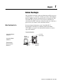
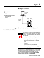
Before You Begin
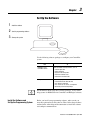
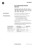
The ControlNet network is a high-speed link that lets PLC processors
and I/O devices (e.g., I/O racks, variable speed drives, Man-Machine
Interface (MMI), and other automation devices) exchange data. The
ControlNet PLC-5 processors have one logical ControlNet port
consisting of two BNC connectors and one network access port; these
processors let you connect to the ControlNet network.
What You Need to Do
If you need more information, see the ControlNet PLC-5
Programmable Controllers User Manual, publication number
1785-UM022 (see page P-1 for information about how to obtain a
copy of this manual).
PC with
Example Configuration
Programming
Set up the Hardware
(Chapter 2)
Set up the Software
(Chapter 3)
Software
1771-P4S
power supply
PC with
Programming
Software
PLC-5/20
Processor
Internal
Power Supply
1786-CP
Troubleshoot the
Processor System
(Chapter 4)
PLC-5/40C
processor
Data Highway
Plus
Publication 1785-QS006C-EN-P - April 2002
1-2
Before You Begin
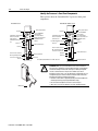
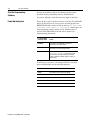
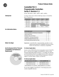
Identify the Processor’s Front Panel Components
These pictures show the ControlNet PLC-5 processor front panel
components.
PLC-5/40C and -5/80C Processors
PLC-5/20C Processor
Battery Status Indicator
Battery Status Indicator
Keyswitch
ControlNet I/O Status Indicator
Channel 2 ControlNet
Status Indicators
ControlNet Network Access
Port
1
Channel 2
Keyswitch
Processor RUN/FAULT
Status Indicator
Force Status Indicator
Channel 0 Communication
ACTIVE/FAULT Status
Indicator
Memory Module Space
Channel 0
ControlNet I/O Status Indicator
Channel 2 ControlNet
Status Indicators
ControlNet Network Access Port
Channel 2
Processor RUN/FAULT
Status Indicator
Force Status Indicator
Channel 0 Communication
ACTIVE/FAULT Status
Indicator
Channel 0
1
Channel 1 Status Indicators
DH+ Programming Terminal
Connection to Channel 1A
Channel 1 Status Indicators
DH+ Programming Terminal
Connection to Channel 1A
Channel 1A
Channel 1A
Battery Compartment
Channel 1B
Channel 1B
1ControlNet Redundant Media Ports - BNC; dedicated
!
Wrist strap
Publication 1785-QS006C-EN-P - April 2002
Memory Module Space
Battery Compartment
ATTENTION: Make sure you understand the anti-static environment.
The processor is shipped in a static-shielded container to guard against
electrostatic damage. Electrostatic discharge can damage integrated
circuits or semiconductors in the processor module if you touch
backplane connector pins. It can also damage the module when you set
configuration plugs or switches inside the module. Avoid electrostatic
damage by observing the following precautions.
• Remain in contact with an approved ground point while handling the
module (by wearing a properly grounded wrist strap).
• Do not touch the backplane connector or connector pins.
• When not in use, keep the module in its static-shielded container.
Before You Begin
Check Your Components
1-3
For this quick start, you need this hardware and software:
Product name:
Catalog number:
Hardware
ControlNet PLC-5 processor
1785-L20C15, -L40C15, -L46C15,
-L80C15
ControlNet network access cable
1786-CP
1771 I/O chassis
1771-A1B
power supply
1771-P4S
personal computer
communication interface card
1784-KTCX15
Software
RSLogix5 programming software 1
• 9324-RL5300END (diskettes)
• or 9324-RL5300ENE (CDROM)
RSNetWorx network
configuration software 1
9357-CNETL3
RSLinx communication software 1
9355-WAB
1
You can order 9324-RWCNTENE to receive RSLogix 5, RSNetWorx, and RSLinx on a single CD.
Publication 1785-QS006C-EN-P - April 2002
1-4
Before You Begin
Notes
Publication 1785-QS006C-EN-P - April 2002
Chapter
2
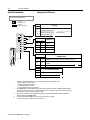
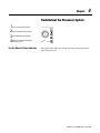
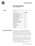
Set Up the Hardware
1
Install the hardware
(page 2-2)
PC with
Programming
Software
the personal computer to
2 Connect
the PLC-5 processor
(page 2-6
PLC-5/20C
Processor
ControlNet network
access cable
(1786-CP) or
serial cable
(1784-CP10)
Internal
Power Supply
For more information, see the ControlNet PLC-5 Programmable
Controllers User Manual, publication number 1785-UM022.
Prevent Electrostatic Discharge
This equipment is sensitive to electrostatic discharge
which can cause internal damage and affect normal
operation. Follow these guidelines when you handle
this equipment:
ATTENTION
!
•
touch a grounded object to discharge potential
static
•
wear an approved grounding wrist strap
•
do not touch connectors or pins on component
boards
•
do not touch circuit components inside the
equipment
•
if available, use a static-safe workstation
•
when not in use, store the equipment in appropriate
static-safe packaging
The PLC-5 processor is a modular component of the 1771-I/O system
that requires a properly installed system chassis. Refer to publication
1771-IN075 for detailed information on compatible chassis and
proper installation and grounding requirements. Limit maximum
adjacent slot power dissipation to 10W maximum.
Publication 1785-QS006C-EN-P - April 2002
2-2
Set Up the Hardware
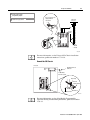
Install the Hardware
Configure the I/O Chassis
switches.
1 SetSetthethebackplane
backplane
switches.
Pressed in
at top ON (closed)
Switch
Pressed in
at bottom OFF (open)
Last State
1
O1
N
O
F
F
on
Outputs of this I/O chassis remain in their last state when
a hardware failure occurs. 1
off
Outputs of this I/O chassis are turned off when a
hardware failure occurs. 1
2
3
Always
Off
Switches
4 5
6 7
8
5
off
off
2 - slot
off
on
1 - slot
on
off
1/2 - slot
on
on
Not allowed
Switches
6
off
7
off
on
on
on
off
Switch
8
1
2`
3´
4ˆ
5˜
Addressing
4
EEPROM Transfer
EEPROM memory transfer to processor memory at power-up. `2, 3´
EEPROM memory transfers to processor memory if processor memory
not valid.
4
EEPROM memory does not transfer to processor memory. ˆ
Processor Memory Protection
off
Processor memory protection disabled.
on
5
Processor memory protection enabled. ˜
Regardless of this switch setting, outputs are turned off when any of the following occurs:
- processor detects a runtime error
- an I/O chassis backplane fault occurs
- you select program or test mode
- you set a status file bit to reset a local rack
If an EEPROM module is not installed and processor memory is valid, the processor's PROC LED indicator blinks,
and the processor sets S:11/9, bit 9 in the major fault status word. To clear this fault, change the processor from
program mode to run mode and back to program mode.
If the processor's keyswitch is set in REMote, the processor enters remote RUN after it powers up and has its
memory updated by the EEPROM module.
A processor fault (solid red PROC LED) occurs if processor memory is not valid.
You cannot clear processor memory when this switch is on.
Publication 1785-QS006C-EN-P - April 2002
2-3
Set Up the Hardware
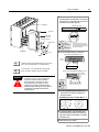
Set the
the power
2 Set
powersupply
supply
configuration jumper.
configuration
jumper.
Are you using a power
supply module in
the chassis?
Install the keying
keyingbands.
bands.
3 Install
PLC-5/20
Processor
Y N
Keying
Bands
YN
O 1
N
O
F
F
2
3
4
2
4
6
8
10
12
14
16
18
20
22
24
26
28
30
32
34
36
38
40
42
44
46
48
50
52
54
56
5
6
between
- 40 & 42
- 54 & 56
7
8
20609-M
For more information, see the Universal I/O Chassis installation
instructions, publication number 1771-2.10.
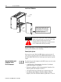
Ground the I/O Chassis
Enclosure
Grounding Electrode
Conductor
Ground
Bus
To Grounding
Electrode System
Ground Lug
Nut and
Captive Washer
Star
Washer
I/O Chassis Wall
Ground Lug
20626-M
For more information, see the Allen-Bradley Programmable
Controller Wiring and Grounding Guidelines, publication number
1770-4.1.
Publication 1785-QS006C-EN-P - April 2002
2-4
Set Up the Hardware
Install the Power Supply
To install the power supply, refer to one of the publications listed
below:
To install one of these power supplies:
See this publication:
Publication number:
1771-P4S, -P6S, -P4S1, -P6S1
1771-P4R, -P64
1771-P7
Power Supply Modules Installation Data
Redundant Power Supply Modules Installation Instructions
AC Power Supply Installation Instructions
1771-2.135
1771-5.30
1771-IN056
Install the PLC-5 Processor
WARNING
!
WARNING
!
Publication 1785-QS006C-EN-P - April 2002
If you insert or remove the processor while
backplane power is on or connect or disconnect any
cables with power applied to the module or to the
device on the other end of the cable, an electrical arc
can occur. This could cause an explosion in
hazardous location installations. Be sure that power
is removed or the area is nonhazardous before
proceeding.
When used in a Class I, Division 2, hazardous
location, this equipment must be mounted in a
suitable enclosure with proper wiring method that
complies with the governing electrical codes.
2-5
Set Up the Hardware
1 Define the DH+ Station Address of Channel 1A
by setting switch assembly SW-1 on the back of
the processor. (See the side of the processor if
you want to use another address.)
Locking Bar
side view of processor
Lift Ejector Tab
PLC-5/20
Processor
1 2 3 4 5 6 7
Battery Connector
Battery Cover
side view
down
57.6 Kbaud
For series E and later processors:
use this switch to select baud rate
For series D and earlier processors:
this switch is always off
up
230 Kbaud
Card Guides
20610-M
2 Specify the digital interface of channel 0.
bottom view of PLC-5/20C processor
Battery
Front of
Processor
More
For detailed information about handling and disposing of the battery
as well as other important guidelines, see publication AG-5.4.
1 2 3 4 5 6 7 8 9 10
More
For more information, see the ControlNet PLC-5 Programmable
Controllers User Manual, publication number 1785-UM022.
bottom view of PLC-5/40C and -5/80C processor
Front of
Processor
WARNING
!
When you connect or disconnect the battery,
an electrical arc can occur. This could cause an
explosion in hazardous location installations.
Be sure that power is removed or the area is
nonhazardous before proceeding. For safety
information on the handling of lithium batteries,
including handling and disposal of leaking batteries,
see Guidelines for Handling Lithium Batteries,
publication AG-5.4.
side view
1 2 3 4 5 6 7 8 9 10
OFF
3 Set the ControlNet network addresses by
using the two 10-digit rotary switches on
top of the module.
ControlNet PLC-5 processor's NET address = 1
20
30
10
2
00
50
60
90
80
70
3
1
40
4
0
5
9
6
8
7
4 To install the battery, slide the battery-side
connector into the processor-side connector
until you hear them snap together, and attach
the battery cover.
5 Install the processor module.
Publication 1785-QS006C-EN-P - April 2002
2-6
Set Up the Hardware
Install the I/O Modules
Locking
Bar
Install each I/O module and connect
the wiring arm. Refer to the user
documentation you recieved with
the I/O module for more detailed
installation requirements.
Card Guides
20618-M
WARNING
!
If you insert or remove the module while backplane
power is on, an electrical arc can occur. This could
cause an explosion in hazardous location
installations. Be sure that power is removed or the
area is nonhazardous before proceeding.
For more information, see the installation instructions or user manual
for the specific module you are installing.
Power Up the System
Power up the system. Check the LED display on the processor. If
your system is operating properly, the PROC LED should be steady
red. If the PROC LED is not red, check operation of power or power
supply.
Connect the Personal
Computer to the
PLC-5 Processor
Publication 1785-QS006C-EN-P - April 2002
To connect the personal computer to the PLC-5 processor, refer to the
following publications:
•
ControlNet PLC-5 Programmable Controllers User Manual,
publication number 1785-UM022
•
Enhanced and Ethernet PLC-5 Programmable Controllers User
Manual, publication number 1785-6.5.12
•
the documentation provided with your communication card
•
Data Highway/Data Highway Plus/Data Highway II/Data
Highway 485 Cable Installation Manual, publication 1770-6.2.2
Chapter
3
Set Up the Software
1
Install the software
2
Start the programming software
3
Powerup the system
Use the following software packages to configure your ControlNet
system.
Use:
To:
RSNetWorx for the
ControlNet network
define ControlNet network parameters, such as:
• network update time
• media redundancy
• physical media configuration
• maximum scheduled nodes
• maximum unscheduled nodes
RSLogix5
•
•
•
•
•
enter user program files
create/delete/monitor data table files
enter module configuration
enter channel 0, 1A, 1B, and, 3 configuration
administer passwords and privileges
For information about using these software packages, see the online
help systems for RSNetWorx for ControlNet and RSLogix5 software.
Install the Software and
Set Up the Programming System
Before you install your programming software, make certain you
meet the requirements for that software. Then, follow the procedures
outlined in the online help and documentation to install the software
and configure communication.
Publication 1785-QS006C-EN-P - April 2002
3-2
Set Up the Software
Start the Programming
Software
Start the programming software by following the procedures
described in your programming software documentation.
If you have difficulty, verify that the power supply is turned on.
Power Up the System
Power up the system if you have not done so already. Check the LED
display on the processor. If your system is operating properly, the
PROC LED should be steady red and the message “Processor RAM
is faulted. Press <Enter> to clear memory” should appear on
the programming software display. See the following table to
proceed. If the PROC LED is not red, turn to chapter 4 for
troubleshooting information.
If your keyswitch
is in this position:
do this:
PROGRAM
Clear memory. The PROC LED should turn off.
The software is in Program mode.
REMOTE
Clear memory. The PROC LED should turn off.
The software is in Remote Program mode.
RUN
You see the message “No access or
privilege violation” because you cannot
clear memory in Run mode. Change the keyswitch
position to Program or Remote and press <Enter> to
clear memory.
To monitor your system as you configure and run it, check the
processor LED display for the following indicators:
Publication 1785-QS006C-EN-P - April 2002
This LED:
lights when:
COMM
you establish serial communication (CH 0)
BATT
no battery is installed or the battery voltage is low
REM I/O
you establish Remote I/O communication
ADAPT
the processor is in adapter mode
FORCE
forces are present in your ladder program
Chapter
4
Troubleshoot the Processor System
11
2
3
4
Use the general status indicators
Use the PLC-5 Processor
Status Indicators
Use(page
the ControlNet
status indicators
4-1)
Use the DH+/RIO status indicators
BATT
PROC
FORCE
COMM
Monitor the ControlNet configuration
and status screens
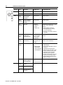
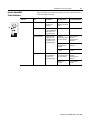
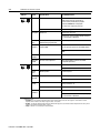
Use the General Status Indicators
The general status indicators inform you of the general operational
state of the processor.
Publication 1785-QS006C-EN-P - April 2002
4-2
Troubleshoot the Processor System
BATT
Indicator
Color
Description
Probable Cause
Recommended Action
BATT
Red
Battery low
Battery low
Replace battery within 10 days
Off
Battery is good
Normal operation
No action required
Green
(steady)
Processor is in run
mode and fully
operational
Normal operation
No action required
Green
(blinking)
Processor memory is
being transferred to
EEPROM
Normal operation
No action required
Red
(blinking)
Major fault
• RSLogix 5
download in
progress
• Run-time error
During RSLogix 5 download, this is normal
operation - wait for download to
complete.
If not during RSLogix 5 download:
• Check major fault bit in status file
(S:11) for error definition
• Clear fault, correct problem, and return
to run mode
Alternating
Red and
Green
Processor in
FLASH-memory
programming mode
Normal operation if
processor's FLASH
memory is being
reprogrammed
No action required - allow flash update to
complete
Red
(steady)
Power cycle with
problem battery
Battery is low,
disconnected or not
installed
Properly replace or install battery (see
Chapter 1 for more information)
Red
(steady)
Fault with memory loss
• New processor
• Use programming software to clear and
initialize memory
• Verify that ControlNet address switch is
not set to 0
• Install battery (to preserve failure
diagnostics), then power down, reseat
processor and power up; then reload
your program. If you are unable to
reload your program, replace the
processor. If you are able to reload your
program and fault persists, contact
Technical Support at 440.646.6800 to
diagnose the problem.
Off
Processor is in program
load or test mode or is
not receiving power
Amber
(steady)
SFC and/or I/O forces
enabled
Amber
(blinking)
SFC and/or I/O forces
present but not enabled
Off
SFC and/or I/O forces
not present
PROC
FORCE
PROC
COMM
FORCE
Publication 1785-QS006C-EN-P - April 2002
• Invalid ControlNet
network address
• Processor has failed
internal diagnostics
Check power supply and connections
Normal operation
No action required
Troubleshoot the Processor System
Use the ControlNet
Status Indicators
I/O
A
B
4-3
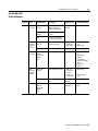
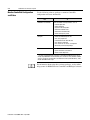
The ControlNet status indicators inform you of the operational state
of the ControlNet network.
Indicator
Color
Description
Probable Cause
Recommended Action
I/O
Off
ControlNet I/O not
present or not
operating
Normal operation if
Channel 2 not being
used
No action required
Steady Green
All nodes configured
in the ControlNet map
table present and
operating properly
Normal operation
No action required
Flashing Green/Off
At least one node
configured for the
ControlNet network
not present or not
operating properly
Cable(s) or
connector(s) broken
or not connected
Repair or replace
cable(s) or
connector(s), and
reconnect
Destination
module(s) bad or
missing
Repair or replace
module(s)
Node(s) not on
network
Connect node to
network
Cable(s) or
connector(s) broken
or not connected
Repair or replace
cable(s) or
connector(s), and
reconnect
Nodes not on
network
Connect nodes to
network
Flashing Red/Off
All nodes configured
for ControlNet not
present or not
operating properly
Publication 1785-QS006C-EN-P - April 2002
4-4
Troubleshoot the Processor System
Indicator
A
and
Color1
Probable Cause
Recommended Action
Off
Internal diagnostics failed
1. Turn power off, make sure ControlNet address is
not 00, reseat processor, then power up
2. Clear memory and reload your program
3. Replace EEPROM with new program
4. If still an error, replace the processor
No power
Check power supply
Faulted unit
Cycle power or reset unit
B
Steady Red
If fault persists, contact your Allen-Bradley Company,
Inc. representative or distributor
Flashing
Green
Normal operation if processor is in
FLASH memory program mode
No action required
Flashing
Red/Green
The processor’s ControlNet address
is above UMAX
Configure the ControlNet network so that UMAX is at
least as high as the processor’s ControlNet address.
Set the processor’s ControlNet address at or below
UMAX.
A
or
Alternating
Red/Green
Self-test
No action required
Alternating
Red/Off
Incorrect node configuration
Check network address and other ControlNet
configuration parameters
Off
Channel disabled
No action required
Configure for ControlNet communication
B
Steady
Green
Normal operation
No action required
Flashing
Green/Off
Temporary errors
No action required
Flashing
Red/Off
Media fault
Check media for broken cables, loose connectors,
missing terminators, etc.
No other nodes present on network
Add other nodes to the network
Incorrect network configuration
Cycle power or reset unit
Flashing
Red/Green
1
Make sure that ControlNet is properly terminated
If fault persists, contact your Allen-Bradley Company,
Inc. representative or distributor
Definition of terms:
• alternating – the two indicators alternate between the two defined states at the same time (applies to both indicators viewed
together); the two indicators are always in opposite states, out of phase
• flashing – the indicator alternates between the two defined states (applies to each indicator viewed independent of the other); if both
indicators are flashing; they flash together, in phase
• steady – indicator is on continuously in the defined state
Publication 1785-QS006C-EN-P - April 2002
Troubleshoot the Processor System
4-5
Use the DH+/RIO
Status Indicators
Indicator
Color
Channel Mode
Description
Probable Cause
Recommended Action
A or B
Green
(steady)
Remote I/O
Scanner
Active Remote I/O link, all
adapter modules are
present and not faulted
Normal
operation
No action required
Remote I/O
Adapter
Communicating with
scanner
DH+
Processor is transmitting
or receiving on DH+ link
Remote I/O
Scanner
At least one adapter is
faulted or has failed
• Power off at
remote rack
• Cable broken
• Restore power to the
rack
• Repair cable
DH+
No other nodes on network
Red
(steady)
Remote I/O
Scanner
Remote I/O
Adapter
DH+
Hardware fault
Hardware error
• Turn power off, then
on.
• Check that the
software
configurations
match the hardware
set-up.
• Replace the
processor.
Red
(blinking
rapidly or
slowly)
Remote I/O
Scanner
Faulted adapters detected
• Cable not
connected or
is broken
• Power off at
remote racks
• Repair cable
Green
(blinking
rapidly or
slowly)
Off
• Restore power to
racks
DH+
Bad communication on
DH+
Duplicate node
detected
Correct station address
Remote I/O
Scanner
Remote I/O
Adapter
DH+
Channel offline
Channel is not
being used
Place channel online if
needed
Publication 1785-QS006C-EN-P - April 2002
4-6
Troubleshoot the Processor System
Monitor ControlNet Configuration
and Status
Use the following software packages to montior ControlNet
configuration and status information.
Use:
To:
RSNetWorx for ControlNet
define ControlNet network parameters, such as:
• network update time
• media redundancy
• physical media configuration
• maximum scheduled nodes
• maximum unscheduled nodes
• monitor I/O map entry status
RSLogix5
•
•
•
•
•
•
RSLinx
to provide the ControlNet network interfaces to:
• poll the network for active devices
• monitor station diagnostics
monitor ControlNet diagnostic file1
enter user program files
create/delete/monitor data table files
enter module configuration
enter channel 0, 1A, 1B, and, 3 configuration
administer passwords and privileges
1 It is highly recommended that you declare an extended ControlNet diagnostic file (63
words) using RSNetWorx. This file will allow you to monitor for noise (via ladder and HMI
query), to monitor the overall health of scheduled connections (words 40 and 41), and to
monitor ControlNet buffer usage.
For information about using these software packages, see the online
help systems for RSNetWorx for ControlNet and RSLogix5 software.
Publication 1785-QS006C-EN-P - April 2002
Appendix
A
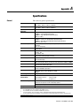
Specifications
General
This table lists general specifications.
Backplane Current
Heat Dissipation
Adjacent Slot Power
Dissipation
Operating Temperature
Storage Temperature
Relative Humidity
Vibration
Shock
Emissions
ESD Immunity
Radiated RF Immunity
EFT/B Immunity
Surge Transient Immunity
Conducted RF Immunity
Enclosure Type Rating
Time-of-Day
Clock/Calendar1
Available Cartridges
Battery
1
2
3
4
5
1785-L20C15:
2.7A @ 5Vdc
1785-L40C15, -L46C15, -L80C15: 3.3A @ 5Vdc
1785-L20C15:
54 BTU/hour
1785-L40C15, -L46C15, -L80C15: 59 BTU/hour
10W maximum
IEC 60068-2-1 (Test Ad, Operating Cold),
IEC 60068-2-2 (Test Bd, Operating Dry Heat),
IEC 60068-2-14 (Test Nb, Operating Thermal Shock):
0-60oC (32–140oF)
IEC 60068-2-1 (Test Ab, Un-packaged Non-operating Cold),
IEC 60068-2-2 (Test Bc, Un-packaged Non-operating Dry Heat),
IEC 60068-2-14 (Test Na, Un-packaged Non-operating Thermal Shock):
–40 to 85oC (–40 to 185oF)
IEC 60068-2-30 (Test Db, Un-packaged Non-operating
Damp Heat):
5–95% non condensing
IEC60068-2-6 (Test Fc, Operating):
2g @10–500Hz
IEC60068-2-27:1987, Test Ea (Unpackaged shock, ES#002)
Operating - 30g
Non-operating - 50g
CISPR 11:
Group 1, Class A (with appropriate enclosure)
IEC 61000-4-2:
4kV contact discharges
IEC 61000-4-3:
10V/m, 3V/m Broadcast Bands, with 1kHz sine-wave 80% AM from 30MHz to 1000Mhz
IEC 61000-4-4:
+2kV at 5kHz on communications ports
IEC 61000-4-5:
+2kV line-earth(CM) on signal ports
IEC 61000-4-6:
10Vrms with 1kHz sine-wave 80%AM from 150kHz
to 30MHz
None (open style)
Maximum Variations at 60° C: ± 5 min per month
Typical Variations at 20° C:
± 20 s per month
Timing Accuracy:
1 program scan
1785-CHBM ControlNet Hot Backup Cartridge2
(required for each processor used in a hot backup system)
1785-RC Relay Cartridge
Allen-Bradley 1770-XYC
The clock/calendar will update appropriately each year.
The 1785-CHBM cannot be used with the 1785-5/60C processor.
The 1785-ME16 cannot be used with ControlNet PLC-5 processors.
For more information, refer to publication 1770-4.1, Industrial Automation Wiring and Grounding Guidelines.
See the Product Certification link at www.ab.com for Declarations of Conformity, Certificates, and other certification details.
Specifications continued on next page
Publication 1785-QS006C - April 2002
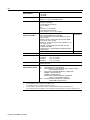
A-2
Memory Modules3
Compatible I/O Modules
Hardware Addressing
Communication Types and
Connectors and Cables
Location
Weight
Keying
Certifications
(when product is marked)
1
2
3
4
5
• 1785-ME32
• 1785-ME64
• 1785-M100
Bulletin 1771 I/O, 1794 I/O, 1746 I/O, and 1791 I/O
including 8-, 16-, 32-pt, and intelligent modules
2-slot
• Any mix of 8-pt modules
• 16-pt modules must be I/O pairs
• No 32-pt modules
1-slot
• Any mix of 8- or 16-pt modules
• 32-pt modules must be I/O pairs
1/2-slot—Any mix of 8-,16-, or 32-pt modules
• Serial - using serial port connector (25-pin D-sub with screw
locks) and cable (Belden 8243 or equivalent)
• DH+ - using Phoenix contact connector (MSTB 2.5/3-ST) and
cable (1771-CD)
• DH using 1785-KA - using Phoenix Contact connector (MSTB
2.5/3-ST) and cable (1771-CD)
• Remote I/O - using Phoenix contact connector (MSTB 2.5/3-ST)
and cable (1771-CD)
• ControlNet - using ControlNet taps (1786-TPYS, 1786-TPS,
1786-TPR, 1786-TPYR)
• Programmng port - using Data Highway programming terminal
cable (1784-CP)
• Relay Cartridge
Wire Category 24
Wire Category 14
1771-A1B, -A2B, A3B, -A3B1, -A4B chassis; left-most slot
PLC-5/20C15:
3 lbs, 3 oz (1.45 kg)
PLC-5/40C15:
3 lbs, 2 oz (1.42 kg)
PLC-5/46C15:
3 lbs, 2 oz (1.42 kg)
PLC-5/80C15:
3 lbs, 2 oz (1.42 kg)
• Between 40 and 42
• Between 54 and 56
UL
UL Listed Industrial Control Equipment
CSA
CSA Certified Process Control Equipment
CSA
CSA Certified Process Control Equipment for Class I, Division 2 Group
A,B,C,D Hazardous Locations
European Union 89/336/EEC EMC Directive, compliant with:
CE5
EN 50081-2; Industrial Emissions
EN 50082-2; Industrial Immunity
European Union 73/23/EEC LVD Directive, compliant with:
EN 61131-2; Programmable Controllers
C-Tick5 Australian Radiocommunications Act, compliant with:
AS/NZS 2064; Industrial Emissions
The clock/calendar will update appropriately each year.
The 1785-CHBM cannot be used with the 1785-5/60C processor.
The 1785-ME16 cannot be used with ControlNet PLC-5 processors.
For more information, refer to publication 1770-4.1, Industrial Automation Wiring and Grounding Guidelines.
See the Product Certification link at www.ab.com for Declarations of Conformity, Certificates, and other certification details.
Publication 1785-QS006C - April 2002
A-3
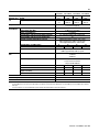
Maximum User Memory Words
Maximum Total
I/O
Any Mix
Complimentary
PLC-5/20C15
16K
512
512 in and 512
out
Program Scan Time
ControlNet I/O3
Transmission Rate
Network Update Time (NUT)
Number of ControlNet Ports
Maximum Number of Nodes per Link without a Repeater
Maximum Number of Nodes per Link with Repeaters
Maximum Link Cable Length without a Repeater
Maximum Number of I/O Map Entries
Maximum DIF/DOF Size
Maximum Link Cable Length with Repeaters
Remote I/O and
DH+
Transmission Rate
I/O Scan Time (Typical)
Maximum Number of Remote I/O Racks
Maximum Number of Remote I/O Devices
Number of Ports Configurable for DH+ or Remote I/O
(Adapter or Scanner)
Number of Dedicated DH+ Ports
Number of Serial Ports
Number of Coprocessor Ports
Maximum Number of MCPs
1
2
3
PLC-5/40C15
PLC-5/46C15
1
1
48K
48K
2048
2048
2048 in and
2048 in and
2048 out
2048 out
0.5 ms per K word (bit logic)
2 ms per K word (typical)
5M bit/s
PLC-5/80C15
100K2
3072
3072 in and
3072 out
2-100 ms (user selectable)
1 (redundant)
48—with 250 m (approx. 820 ft) cable length
99
1,000 m (approximately 3,280 ft)—with 2 nodes
500 m (approximately 1,640 ft)—with 32 nodes
250 m (approximately 820 ft)—with 48 nodes
64
96
96
128
2000 words
3000 words
3000 words
4000 words
6,000 m (approximately 19,680 ft)—with 2 nodes
3,000 m (approximately 9,840 ft)—typical
57.6K bit/s
115.2K bit/s
230.4K bit/s
10 ms per rack @ 57.6K bit/s
7 ms per rack @ 115.2K bit/s
3 ms per rack @ 230K bit/s
3
15
15
23
12
60
60
92
1
2
2
2
1
0
0
0
1
1
16
The PLC-5/40C15 and -5/46C15 processors have a limit of 32K words per data-table file.
The PLC-5/80C15 processor has a limit of 56K words per program file and 32 K words per data table file. The PLC-5/80C processor has 64K words of total data
table space.
For more information, see the ControlNet Cable System Planning and Installation Manual, publication 1786-6.2.1.
Publication 1785-QS006C - April 2002
A-4
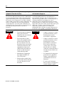
The following information applies when operating this
equipment in hazardous locations:
Informations sur l’utilisation de cet équipement en
environnements dangereux :
Products marked “CL I, DIV 2, GP A, B, C, D” are suitable
for use in Class I Division 2 Groups A, B, C, D, Hazardous
Locations and nonhazardous locations only. Each product is
supplied with markings on the rating nameplate indicating
the hazardous location temperature code. When combining
products within a system, the most adverse temperature code
(lowest “T” number) may be used to help determine the
overall temperature code of the system. Combinations of
equipment in your system are subject to investigation by the
local Authority Having Jurisdiction at the time of
installation.
Les produits marqués "CL I, DIV 2, GP A, B, C, D" ne
conviennent qu’à une utilisation en environnements de
Classe I Division 2 Groupes A, B, C, D dangereux et non
dangereux. Chaque produit est livré avec des marquages sur
sa plaque d’identification qui indiquent le code de
température pour les environnements dangereux. Lorsque
plusieurs produits sont combinés dans un système, le code de
température le plus défavorable (code de température le plus
faible) peut être utilisé pour déterminer le code de
température global du système. Les combinaisons
d’équipements dans le système sont sujettes à inspection par
les autorités locales qualifiées au moment de l’installation.
RISQUE D’EXPLOSION
EXPLOSION HAZARD
WARNING
•
!
Do not disconnect equipment
unless power has been
removed or the area is known
to be nonhazardous.
•
Do not disconnect connections to this equipment unless
power has been removed or
the area is known to be nonhazardous. Secure any external
connections that mate to this
equipment by using screws,
sliding latches, threaded connectors, or other means provided with this product.
•
Substitution of components
may impair suitability for
Class I, Division 2.
•
If this product contains batteries, they must only be changed
in an area known to be nonhazardous.
Publication 1785-QS006C - April 2002
AVERTISSMENT
•
!
Couper le courant ou s’assurer
que l’environnement est classé
non dangereux avant de
débrancher l'équipement.
•
Couper le courant ou s'assurer
que l’environnement est classé
non dangereux avant de
débrancher les connecteurs.
Fixer tous les connecteurs
externes reliés à cet équipement à l'aide de vis, loquets
coulissants, connecteurs filetés
ou autres moyens fournis avec
ce produit.
•
La substitution de composants
peut rendre cet équipement
inadapté à une utilisation en
environnement de Classe I,
Division 2.
•
S’assurer que l’environnement est classé non dangereux
avant de changer les piles.
How Are We Doing?
Your comments on our technical publications will help us serve you better in the future.
Thank you for taking the time to provide us feedback.
You can complete this form and mail it back to us, visit us online at www.ab.com/manuals, or
email us at [email protected]
Pub. Title/Type ControlNet PLC-5 Programmable Controllers Quick Start
Cat. No.
1785-L20 to -L80C15
Pub. No. 1785-QS006C-EN-P
Pub. Date April 2002
Part No.
957678-96
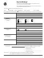
Please complete the sections below. Where applicable, rank the feature (1=needs improvement, 2=satisfactory, and 3=outstanding).
Overall Usefulness
Completeness
(all necessary information
is provided)
Technical Accuracy
(all provided information
is correct)
1
2
3
How can we make this publication more useful for you?
1
2
3
Can we add more information to help you?
1
Clarity
1
(all provided information is
easy to understand)
Other Comments
2
3
procedure/step
illustration
feature
example
guideline
other
explanation
definition
Can we be more accurate?
text
2
3
illustration
How can we make things clearer?
You can add additional comments on the back of this form.
Location/Phone
Your Name
Your Title/Function
Would you like us to contact you regarding your comments?
___No, there is no need to contact me
___Yes, please call me
___Yes, please email me at __________________________
___Yes, please contact me via ________________________
Return this form to:
Allen-Bradley Marketing Communications, 1 Allen-Bradley Dr., Mayfield Hts., OH 44124-9705
Phone: 440-646-3176 Fax: 440-646-3525 Email: [email protected]
Publication ICCG-5.21- January 2001
PN 955107-82
PLEASE FASTEN HERE (DO NOT STAPLE)
PLEASE FOLD HERE
NO POSTAGE
NECESSARY
IF MAILED
IN THE
UNITED STATES
BUSINESS REPLY MAIL
FIRST-CLASS MAIL PERMIT NO. 18235 CLEVELAND OH
POSTAGE WILL BE PAID BY THE ADDRESSEE
1 ALLEN-BRADLEY DR
MAYFIELD HEIGHTS OH 44124-9705
PLEASE REMOVE
Other Comments
Publication 1785-QS006C-EN-P - April 2002 9
Supersedes Publication 1785-10.6 - November 1998
PN 957678-96
Copyright © 2002 Rockwell Automation. All rights reserved. Printed in the U.S.A.