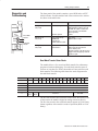
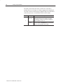
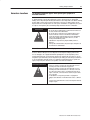
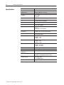
1
Looking for more information?
Visit us on the web at http://www.artisan-scientific.com for more information:
• Price Quotations • Drivers· Technical Specifications. Manuals and Documentation
Artisan Scientific is You~ Source for: Quality New and Certified-Used/Pre:-awned ECJuiflment
• Fast Shipping and DelIve1y
• Tens of Thousands of In-Stock Items
• Equipment Demos
• Hundreds of Manufacturers Supported
• Leasing / Monthly Rentals
Service Center Repairs
Experienced Engineers and Technicians on staff in our
State-of-the-art Full-Service In-House Service Center Facility
• Consignment
InstraView Remote Inspection
Remotely inspect equipment before purchasing with our
Innovative InstraView-website at http://www.instraview.com
We bUy used equipment! We also offer credit for Buy-Backs and Trade-Ins
Sell your excess. underutilized. and idle used equipment. Contact one of our Customer Service Representatives todayl
Talk to a live person: 88EM38-S0URCE fB88-887-68721 I Contact us by email: [email protected] I Visit our website: http://www.artisan-scientific.com
Installation Instructions
!+,4 ,&0/ ,4 64(' 8+(/
$'',5,0/$- ,/)03.$5,0/
,4 $7$,-$%-( ,/ 5+( 16%-,&$5,0/
;"
Use this document as a guide when installing the 1771-OFE analog
output module.
.1035$/5 "4(3 /)03.$5,0/
"/'(345$/' 30'6&5 0.1$5,%,-,59
$-&6-$5( 08(3 (26,3(.(/54
(5(3.,/( 0'6-( -$&(.(/5
(5 5+( 0'6-( 0/),*63$5,0/ 6.1(34
/45$-- 5+( (9,/* $/'4
/45$-- 5+( 0'6-( $/' ,(-' #,3,/* 3.
0//(&5 #,3,/* 50 5+( ,(-' #,3,/* 3.
306/' 5+( +$44,4 $/' 0'6-(
0/),*63( 5+( 0'6-(
,$*/045,&4 $/' !306%-(4+005,/*
$:$3'064 0&$5,0/4
1(&,),&$5,0/4
Because of the variety of uses for the products described in this
publication, those responsible for the application and use of these
products must satisfy themselves that all necessary steps have been
taken to assure that each application and use meets all performance
and safety requirements, including any applicable laws, regulations,
codes and standards. In no event will Rockwell Automation be
responsible or liable for indirect or consequential damage resulting
from the use or application of these products.
Any illustrations, charts, sample programs, and layout examples
shown in this publication are intended solely for purposes of
example. Since there are many variables and requirements associated
with any particular installation, Rockwell Automation does not
assume responsibility or liability (to include intellectual property
liability) for actual use based upon the examples shown in this
publication.
6%-,&$5,0/ &50%(3 2
Analog Output Module
Allen–Bradley publication SGI–1.1, Safety Guidelines for
Application, Installation, and Maintenance of Solid–State Control
(available from your local Rockwell Automation office), describes
some important differences between solid–state equipment and
electromechanical devices that should be taken into consideration
when applying products such as those described in this publication.
Reproduction of the contents of this copyrighted publication, in
whole or part, without written permission of Rockwell Automation,
is prohibited.
Throughout this publication, notes may be used to make you aware
of safety considerations. The following annotations and their
accompanying statements help you to identify a potential hazard.
avoid a potential hazard, and recognize the consequences of a
potential hazard.
!
!
Identifies information about practices or
circumstances that can cause an explosion in a
hazardous environment, which may lead to
personal injury or death, property damage, or
economic loss.
Identifies information about practices or
circumstances that may lead to personal injury or
death, property damage, or economic loss.
Identifies information that is critical for
IMPORTANT successful application and understanding of the
product.
Analog Output Module
!
3
Environment and Enclosure
This equipment is intended for use in a Pollution
Degree 2 industrial environment, in overvoltage
Category II applications (as defined in IEC
publication 60664–1), at altitudes up to 2000
meters without derating.
This equipment is considered Group 1, Class A
industrial equipment according to IEC/CISPR
Publication 11. Without appropriate precautions,
there may be potential difficulties ensuring
electromagnetic compatibility in other
environments due to conducted as well as radiated
disturbance.
This equipment is supplied as “open type”
equipment. It must be mounted within an
enclosure that is suitably designed for those
specific environmental conditions that will be
present, and appropriately designed to prevent
personal injury resulting from accessibility to live
parts. The interior of the enclosure must be
accessible only by the use of a tool. Subsequent
sections of this publication may contain additional
information regarding specific enclosure type
ratings that are required to comply with certain
product safety certifications.
See NEMA Standards publication 250 and IEC
publication 60529, as applicable, for explanations
of the degrees of protection provided by different
types of enclosures. Also, see the appropriate
sections in this publication, as well as the
Allen–Bradley publication 1770–4.1, (“Industrial
Automation Wiring and Grounding Guidelines”),
for additional installation requirements pertaining
to this equipment.
4
Analog Output Module
Preventing Electrostatic Discharge
This equipment is sensitive to electrostatic
discharge, which can cause internal damage and
affect normal operation. Follow these guidelines
when you handle this equipment:
• Touch a grounded object to discharge potential
static.
• Wear an approved grounding wriststrap.
• Do not touch connectors or pins on component
boards.
• Do not touch circuit components inside the
equipment.
• If available, use a static–safe workstation.
• When not in use, keep modules in appropriate
static–safe packaging.
ATTENTION
!
Understand Product
Compatibility
The 1771-OFE module can be used with any 1771 I/O chassis.
Compatibility and data table use is listed below.
Use of Data Table
C
Catalog
Number
,
Compatibility
Input
Image
Bits
Output
Image
Bits
Read
Block
Words
Write
Block
Words
1/2ĆSlot
1ĆSlot
2ĆSlot
Chassis
S i
Series
Addressing
%#&)!" +!) , , ,
%#&)!" +!) , , , , ,
%#&)!" +!) %*) '()'!)!%$
Calculate Power
Requirements
The analog output module receives its power through the 1771 I/O
chassis backplane from the chassis power supply. It does not require
any other external power supply. When planning your system, you
must consider the power usage of all modules in the I/O chassis to
prevent overloading the I/O chassis backplane and/or power supply.
Add this to the requirements of all other modules in the I/O chassis.
Analog Module
,
,
,
*"!)!%$ )%' Power Requirement
Analog Output Module
5
Place your module in any I/O module slot of the I/O chassis except
for the left-most slot. This slot is reserved for PC processors or
adapter modules.
ATTENTION
!
Group your modules to minimize adverse affects
from radiated electrical noise and heat. We
recommend the following.
• Group analog output and low voltage dc
modules away from ac modules or high voltage
dc modules to minimize electrical noise
interference.
• Do not place this module in the same I/O group
with a discrete high-density I/O module when
using 2-slot addressing.
• Limit adjacent slot power dissipation to 10W
maximum.
The module configuration jumpers consist of:
• the last state configuration jumper (all versions)
• the voltage range configuration jumpers (1771-OFE1 only).
The type of module you have dictates how you set the configuration
jumpers.
There are three versions of the analog output module:
(
!%
( ( % '
! &#%!
&"#$
(
&## %
(
%!#' $%
(
&## %
(
%!#' $%
Current version modules (1771-OFE2 and -OFE3) have all
configuration jumpers installed and require no additional
configuration. The configuration jumper for the LAST STATE mode
output level is in the default position (MID). Refer to the section
entitled “Set the Last State Configuration Jumpers” for additional
configuration information.
&%! %!# 6
Analog Output Module
# $# $# !" # $
If you are using the voltage output version (1771-OFE1), you must
set several configuration jumpers on the module’s circuit board. You
must set these jumpers before you can proceed with configuring the
module. When you set these jumpers, you configure each channel for
one of the three voltage ranges listed above. The module is shipped
with the jumpers in the +10V position.
# # "# ## $!# $ !"
The LAST STATE configuration jumpers determine the value of all
the module’s outputs whenever communication between the module
and the processor is lost. This condition occurs when a processor or
adapter faults, or the processor is placed in the PROG or TEST
mode, or if the remote I/O cable breaks.
This is a significant safety feature. You can choose to have the
module’s outputs go to the minimum, middle or maximum of their
respective ranges or hold their last state if a module or system fault
occurs or if the system processor changes from RUN to PROG
mode.
You do this by placing the LAST STATE configuration jumpers on
eight (four jumpers on sets of pins) of the stake pins corresponding
to MIN, MID or MAX. If you do not place configuration jumpers in
one of these positions, the module defaults to the HOLD LAST
VALUE setting.
• On power-up, the module’s output is
disabled until the module receives the first
block transfer write. The output then enables
with the value that you send it in the block
transfer write block.
• We ship 1771-OFE modules with the LAST
STATE configuration jumpers in the MID
position.
IMPORTANT
ATTENTION
!
$!# $ ! ##
%# ##
Switch 1 of the I/O rack affects the function of the
configuration settings as indicated in the table below.
Rack switch 1 determines what output conditions occur during a rack
fault.
Analog Output Module
To set the last state configuration jumpers,
proceed as follows.
ATTENTION
!
+ /" /%" (./ .//" +*#&$0-/&+* '0),"-. +0 !+ *+/ *""! /+
-")+1" /%" )+!0(" +1"-
./ //" 0/,0/ "1"(
+*#&$0-/&+* 0),"-.
Do not insert modules
into or remove modules
from the I/O chassis
while system power is
ON. Failure to observe
this rule could result in
damage to module
circuitry and unexpected
machine operation.
-+*/ +# &- 0&/ +-!
+, &"2
4)
)
)
)
4
)
)
)
)
4
4
4
These output conditions are active only if
the following conditions exist:
• the module faults
• the processor is in the PROGRAM or
TEST mode
• rack switch 1 is in the reset position
-"#0((3 ,0(( 0, +* /%" '0),"- /+ -")+1" &/ #-+) /%" ,&*.
-"#0((3 -",+.&/&+* /%" '0),"- /+ -"#(" / /%" !".&-"! 1(0". &*
/%" /(" /+ /%" ("#/
0(& /&+* /+"- 7
8
Analog Output Module
Set the Voltage Range Configuration Jumpers (1771ĆOFE1 only)
If you ordered the voltage output version, you must set several
configuration jumpers located inside the module on the circuit board.
2
/#!4% 4(% #/.&)'52!4)/. *5-0%23 !.$ 3%4 4(%- !##/2$).' 4/ 8/52 /54054 6/,4!'% 2%15)2%-%.43
LAST STATE
In
Out
3)$% 6)%7
/& *5-0%2
Install the Keying Bands
ATTENTION
!
Observe the following precautions
when inserting or removing keys:
/.&)'52!4)/.
5-0%2
/#!4)/.
%3)2%$ /,4!'% !.'%
54054
(!..%,
5-0%2 .
.
54
54
54
54
10V
54
54
.
.
54
54
5-0%2 .
.
54
54
54
54
54
54
.
.
54
54
54
54
54
54
.
.
5-0%2 .
.
54
54
54
54
54
54
.
.
54
54
54
54
54
54
.
.
5-0%2 .
.
54
54
54
54
54
54
.
.
54
54
54
54
54
54
.
.
0-10V
1-5V
54
54
54
54
.
.
/3)4)/. 4(% +%8).' "!.$3 ). 4(% "!#+0,!.% #/..%#4/23 4/
#/22%30/.$ 4/ 4(% +%8 3,/43 /. 4(% -/$5,%
,!#% 4(% +%8).' "!.$3
"%47%%. 10 !.$ 12
"%47%%. 26 !.$ 28
• Insert or remove keys with your
fingers.
• Make sure the key placement is
correct
Incorrect keying or the use of a tool
can result in damage to the
backplane connector and possible
system faults.
00%2
/..%#4/2
#(!33)3
/5 #!. #(!.'% 4(% 0/3)4)/. /& 4(%3% "!.$3 )&
35"3%15%.4 3834%- $%3)'. !.$ 2%7)2).' -!+%3
).3%24)/. /& ! $)&&%2%.4 480% /& -/$5,% .%#%33!28
5",)#!4)/. #4/"%2 Analog Output Module
!
WARNING
!
9
Remove power from the 1771 I/O chassis
backplane and field wiring arm before removing
or installing an I/O module.
• Failure to remove power from the backplane or
wiring arm could cause module damage, degradation of performance, or injury.
• Failure to remove power from the backplane
could cause injury or equipment damage due to
possible unexpected operation.
When you insert or remove the module with
power applied, or connect or disconnect the field
wiring arm with field side power applied, an
electrical arc can occur. This could cause an
explosion in hazardous location installations.
Be sure that power is removed or the area is
nonhazardous before proceeding.
1%,%)# ,(
..$ .$! 1%,%)# ,( 4 .* .$! $*,%3*).'
, . .$! *..*( *" .$! $--%-
$! 1%,%)# ,( +%0*.- /+1, ) *))!.- 1%.$
.$! (* /'! -* 2*/ ) %)-.'' *, ,!(*0! .$!
(* /'! 1%.$*/. %-*))!.%)# .$! 1%,!-
4
,!(*0!
$*,%3*).' ,
4 4
4 4 4 $--%'*&%)# .
4 4
4 4 !,%!- $--%'*&%)# , +%)
'*&%)# ,
, #/% !, #/% !-
(* /'!
)+ .$! $--%- '.$ *0!,
.$! .*+ *" .$! (* /'! .* -!/,! %.
(* /'!
1%)# .$! $--%- '*&%)# , *1) %).* +'! .* -!/,!
.$! (* /'!- &! -/,! .$! '*&%)# +%)- !)##!
/'%.%*) .*!, 10
Analog Output Module
The 1771–OFE modules are a modular component of the 1771 I/O
system requiring a properly installed system chassis. Refer to
publication 1771–IN075 for detailed information on acceptable
chassis and proper installation and grounding requirements. Limit
the maximum adjacent slot power dissipation to 10W maximum.
Connect your I/O devices to the cat. no. 1771-WC wiring arm
shipped with the module.
!
WARNING
!
Remove power from the 1771 I/O chassis
backplane and field wiring arm before removing
or installing an I/O module.
• Failure to remove power from the backplane or
wiring arm could cause module damage, degradation of performance, or injury.
• Failure to remove power from the backplane
could cause injury or equipment damage due to
possible unexpected operation.
If you connect or disconnect wiring with
field–side power is on, an electrical arc can occur.
This could cause an explosion in hazardous
location installations. Be sure that power is
removed or the area is nonhazardous before
proceeding.
0$/ + ),& $3("$
2+"1(,+ )
/,2+#
0$/602--)($# ),,- -,4$/
(% /$.2(/$#
'$ 6 *,#2)$ #,$0 +,1 02--)5 ),,- -,4$/ %,/
),,-6-,4$/$# + ),& #$3("$0 1/ +0*(11$/0 1/ +0#2"$/0 $1"
,,- -,4$/ *201 !$ 02--)($# !5 1'$ 20$/
0$ $)#$+ 0'($)#$# " !)$ %,/ 0(&+ ) 1/ +0*(00(,+ 1, 1'$
+ ),& #$3("$0 '(0 " !)$ ",+0(010 ,%
0(+&)$ (+02) 1$#
14(01$#6- (/ ,% ",+#2"1,/0 ",3$/$# ),+& 1'$(/ $+1(/$ )$+&1' !5 %,()
0'($)# +# $+" 0$# (+ -) 01(" '$ 0'($)# /$#2"$0 1'$ $%%$"1 ,%
(+#2"$# +,(0$ 1 +5 -,(+1 ),+& 1'$ " !)$
2!)(" 1(,+ "1,!$/ ' ++$) ,21-21 )$ #
' ++$) ,21-21 6 )$ #
' ++$) ,21-21 )$ #
' ++$) ,21-21 6 )$ #
' ++$) ,21-21 )$ #
' ++$) ,21-21 6 )$ #
' ++$) ,21-21 )$ #
' ++$) ,21-21 6 )$ #
,1 20$#
,1 20$#
($)# (/(+& /*
1 , 6
Analog Output Module
Use the following diagrams to ground your
I/O chassis and analog input module. Follow
these steps to prepare the cable:
"*'0 ;17 %100'%6 )4170&+0) %10&7%6145 61 6*' %*#55+5
)4170&+0) 567& 2.#%' # 56#4 9#5*'4 70&'4 6*' (+456 .7) 6*'0
2.#%' # 076 9+6* %#26+8' .1%- 9#5*'4 10 612 1( '#%* )4170& .7)
1437' 6*' 076 9+6* %#26+8' 9#5*'4 61 2170&+0%*'5
'/18' # .'0)6* 1( %#$.'
,#%-'6 (41/ 6*' '.&'0 %#$.'
4170& 7)
76
'.&'0 #$.'
7.. 6*' (1+. 5*+'.& #0& $#4'
&4#+0 9+4' (41/ 6*' +057.#6'& 9+4'5
76 #0& #26+8'
"#5*'4
4170&+0) 67&
#4' &4#+0
9+4'
057.#6'&
9+4'5
11
6#4
"#5*'4
*#55+5
+&' .#6'
4170& 7)
*+'.& #0& 4#+0
69+56'& 61)'6*'4
!5' 6*' %72 9#5*'4 +( %4+/2<10 .7)5 #4' 016 75'&
1+.
5*+'.&
9+56 6*' (1+. 5*+'.& #0& &4#+0
9+4' 61)'6*'4 61 (14/ # 5+0).' 564#0&
66#%* # )4170& .7)
:6'0& 5*+'.& 61 6'4/+0#6+10 21+06
:215' ,756 '017)* %#$.' 61 #&'37#6'.;
6'4/+0#6' +00'4 %10&7%6145
!5' *'#6 5*4+0- 67$+0)
14 16*'4 57+6#$.' +057.#<
6+10 9*'4' 9+4' ':+65
%#$.' ,#%-'6
"*'0 75+0) 5*+'.&'& %#$.' 9+4' )4170& 6*' (1+. 5*+'.&
#0& &4#+0 9+4' 10.; #6 10' '0& 1( 6*' %#$.' "' 4'%1/<
/'0& 6*#6 ;17 94#2 6*' (1+. 5*+'.& #0& &4#+0 9+4' 61<
)'6*'4 #0& %100'%6 6*'/ 61 # %*#55+5 /1706+0) $1.6
6 6*' 12215+6' '0& 1( 6*' %#$.' 6#2' ':215'& 5*+'.&
#0& &4#+0 9+4' 9+6* '.'%64+%#. 6#2' 61 +057.#6' +6 (41/
'.'%64+%#. %106#%6
Refer to Wiring and Grounding Guidelines,
publication 1770-4.1 for additional
information.
*+'.& #0& 4#+0
69+56'& 61)'6*'4
*4'#&<(14/+0) 5%4'9
:6'40#.<6116*
"#5*'45
7$.+%#6+10 %61$'4 12
Analog Output Module
Configure the Module
.0 %&2"*+&% $.-'*(30"2*.*-'.0,"2*.- 1&& $)"/2&0 .' 6.30 /3#+*$"2*.7
Because of the many analog devices available and the wide variety
of possible applications, you must configure the module to conform
to the analog device and specific application that you have chosen.
Use the configuration information below to configure your module
to your specifications.
Word/Dec. Bit
15
14
13
12
11
10
09
08
07
06
05
04
03
02
01
00
Word/Octal Bit
17
16
15
14
13
12
11
10
07
06
05
04
03
02
01
00
)"--&+ "2" "+3&
)"--&+ "2" "+3&
)"--&+ "2" "+3&
)"--&+ "2" "+3&
!.0% )"--&+
)"--&+
)"--&+
)"--&+
"2".0,"2
*-"06
"2"*(-.+"0*26
&("2*4&
.1*2*4&
&1&04&%
"5*,3,$"+*-( "+3&.+"0*26
&("2*4&
.1*2*4&
.%3+&&'"3+2.-'*(30"2*.-
"2".0,"2
.$"+*-(
"2"*(-.+"0*26.1*2*4&
)"--&+ *-*,3, $"+*-( "+3&
)"--&+ "5*,3, $"+*-( "+3&
)"--&+ *-*,3, $"+*-( "+3&
)"--&+ "5*,3, $"+*-( "+3&
)"--&+ *-*,3, $"+*-( "+3&
)"--&+ "5*,3, $"+*-( "+3&
)"--&+ *-*,3, $"+*-( "+3&
)"--&+ "5*,3, $"+*-( "+3&
3#+*$"2*.- $2.#&0 *-*,3,$"+*-( "+3&.+"0*26
&("2*4&
.1*2*4&
Analog Output Module
Diagnostics and
Troubleshooting
The front panel of the module contains a green RUN and a red FLT
(fault) indicator. Possible module fault causes and corrective actions
are shown in the table below.
Indicators
1&&. *.%*$"3/1
13
&% *.%*$"3/1
Probable Cause
Recommended Action
(1&&. /.
1&% /''
6"*3*.( $/.'*(41"3*/. ! 3 0/6&140 3)& -/%4,& /43043 *2
%*2"#,&% 4.3*, 3)& -/%4,& 1&$&*5&2 3)&
'*123 ! )& /43043 *2 &."#,&% ".%
(/&2 3/ 3)& 5",4& 2&.3 *. 3)& !
./1-", /0&1"3*/.
/1-", /0&1"3*/.
/.&
(1&&. /.
1&% /.
.24$$&22'4, 0/6&1940
'"4,3
)&$+24- &11/1
"1%6"1& '"*,41& *. -/%4,&
8$,& 0/6&1
&341. -/%4,& '/1 1&0"*1
(1&&. /''
1&% /''
/ 0/6&1
"% *.3&1.", '42&
41. /'' 0/6&1
&-/5& ".% 1&*.2&13 -/%4,& *.3/
$)"22*2 &341. 0/6&1
' 01/#,&- 23*,, &7*232 ".% $)"22*2 0/6&1
2400,8 *2 '4.$3*/.*.( 01/0&1,8 1&341. 3)&
-/%4,& '/1 1&0"*1
Read Block Transfer Status Words
The module allows a five-word read block transfer for rudimentary
program or hardware debugging. If a read block transfer request is
for more or less than five words, the module will not perform a read
block transfer. The following table shows the word assignment for
the read block transfer.
Decimal Bit
15
14
13
12
11
10
09
08
07
06
05
04
03
02
01
00
Octal Bit
17
16
15
14
13
12
11
10
07
06
05
04
03
02
01
00
!/1% )"..&, .043 "3"
)"..&, .043 "3"
)"..&, .043 "3"
)"..&, .043 "3"
/3
42&%
&2&3
&2&15&%
"3" ",*%
The first four words of the read block transfer show the actual 12 bits
of data sent to the module’s digital-to-analog converters (DACs).
The first four words in the read block transfer appear in 12-bit binary
format regardless of the module’s mode of operation (BCD or 12-bit
binary).
4#,*$"3*/. $3/#&1 14
Analog Output Module
The fifth word contains the status of each DAC word; that is,
whether data is out of range or scaling is improperly programmed.
The fifth word also indicates that I/O RESET has been established
(when the processor is in the PROG/TEST or RUN mode).
&/. 3
%"* ."/ &*!& /" &*1(&! %**"( !/ &. ."*/ /+ /%"
)+!0(" %"." &/. -" *+/ -"."/ 0*/&( +--" / 2-&/"
(+ ' /-*.#"- &. ."*/ &/ +--".,+*!. /+ %**"( &/ /+ %**"( *! .+ +*
&/ . /%" &/ %"* ."/ &/ &*!& /". /%/ /%" ,-+3
"..+- &. &* +- )+!" &" (+ ' /-*.3
#"- !/ &. *+/ "&*$ 2-&//"* /+ /%" )+!0("
0(& /&+* /+"- Analog Output Module
Hazardous Locations
15
The following information applies when operating this equipment in
hazardous locations:
Products marked CL I, DIV 2, GP A, B, C, D" are suitable for use in Class I Division 2 Groups A, B,
C, and D Hazardous Locations and nonhazardous locations only. Each product is supplied with
markings on the rating nameplate indicating the hazardous location temperature code. When combining
products within a system, the most adverse temperature code (lowest T" number) may be used to
help determine the overall temperature code of the system. Combinations of equipment in your system
are subject to investigation by the local Authority Having Jurisdiction at the time of installation.
WARNING
!
EXPLOSION HAZARD • Do not disconnect equipment unless power has been removed or
the area is known to be nonhazardous.
• Do not disconnect connections to this equipment unless power
has been removed or the area is known to be nonhazardous.
Secure any external connections that mate to this equipment by
using screws, sliding latches, threaded connectors, or other
means provided with this product.
• Substitution of components may impair suitability for Class I,
Division 2.
• If this product contains batteries, they must only be changed in an
area known to be nonhazardous.
Informations sur l'utilisation de cet équipement en environnements dangereux:
Les produits marqués CL I, DIV 2, GP A, B, C, D ne conviennent que une utilisation en environnements
de Classe I Division 2 Groupes A, B, C, D dangereux et non dangereux. Chaque produit est livré
avec des marquages sur sa plaque d'identification qui indiquent le code de température pour les
environnements dangereux. Lorsque plusieurs produits sont combinés dans un systéme, le code de
température le plus défavorable (code de température le plus faible) peut eatre utilisé pour déterminer
le code de température global du systéme. Les combinaisons d'equipements dans le systéme sont
sujettes à inspection par les autorités locales qualifiées au moment de l'installation.
AVERTISSEMENT
!
RISQUE D'EXPLOSION • Couper le courant ou s'assurer que l'environnement est classé
non dangereux avant de débrancher l'équipement.
• Couper le courant ou s'assurer que l'environnement est classé
non dangereux avant de débrancher les connecteurs. Fixer tous
les connecteurs externes reliés à cet équipement à l'aide de vis,
loquets coulissants, connecteurs filetés ou autres moyens fournis
avec ce produit.
• La substitution de composants peut rendre cet équipement
inadapté à une utilisation en environnement de Classe 1, Division
2.
• S'assurer que l'environnement est classé non dangereux avant de
changer les piles.
Publication 1771-IN044C-EN-P - October 2002
16
Analog Output Module
Outputs per Module
4 Individually Isolated
Module Location
Bulletin 1771 I/O Chassis - One Slot
Output Voltage Ranges (Nominal) 1771ĆOFE1
+1 to +5V DC
-10 to +10V DC
0 to +10V DC
Output Current (maximum)
10mA per Channel in Voltage Mode (1771-OFE1)
Output Current Ranges (Nominal)
+4 to +20mA, 5V dc (1771-OFE2)
0 to +50mA, 12.5V dc (1771-OFE3)
Digital Resolution
12ĆBit Binary - 1 Part in 4095
Output Capacitance
0.01µF (Voltage Outputs)
0.022µF (Current Outputs)
Output Impedance
<0.25 ohms for Voltage Outputs Exclusive of Contact Wiring
Resistance
>1.5 megohms for Current Outputs
Max Loop Impedance in the
Current Mode
1771ĆOFE2 - Up to 1200 ohms Load Resistance
1771ĆOFE3 - Up to 400 ohms Load Resistance
Output Overload Protection
All outputs are protected against short circuit load conditions
not to exceed one minute.
Backplane Power
1771ĆOFE1 - 1.50A
1771ĆOFE2 - 1.50A
1771ĆOFE3 - 2.50A
Power Dissipation
1771ĆOFE1 - 7.9W
1771ĆOFE2 - 7.9W
1771ĆOFE3 - 13.1W
Thermal Dissipation
1771ĆOFE1 - 26.9 BTU/hr
1771ĆOFE2 - 26.9 BTU/hr
1771ĆOFE3 - 44.5 BTU/hr
Adjacent Slot Power Dissipation
10 Watts (max.)
Isolation Voltage
Tested to 850V dc for 1s
D/A Converter Specifications
Settling Time
0.8 ms Maximum for a Resistive Load
Internal Scan Rate
8.0 ms for All Channels Using BCD Data and Scaling 1.6 ms
for All Channels Using Binary Data and No Scaling
Accuracy (Including Linearity, Gain,
and Offset at 25oC)
+0.1% of Full Scale
+1/2 LSD (BCD Mode)
+1/2 LSB (BINARY Mode)
Temperature Coefficient
+50 ppm/oC of Full Scale Range
Publication 1771-IN044C-EN-P - October 2002
Analog Output Module
17
Environmental Conditions
Operating
Temperature
IEC 60068-2-1 (Test Ad, Operating Cold)
IEC 60068-2-2 (Test Bd, Operating Dry Heat)
IEC 60068-2-14 (Test Nb, Operating Thermal Shock)
32 to 140°F (0 to 60°C)
Storage Temperature
IEC 60068-2-1 (Test Ab, Unpackaged, Nonoperating Cold)
IEC 60068-2-2 (Test Bb, Unpackaged, Nonoperating Dry
Heat)
IEC 60068-2-14 (Test Na, Unpackaged, Nonoperating
Thermal Shock)
-40 to 185°F (-40 to 85°C)
Relative Humidity
IEC 60068-2-30 (Test Db, Unpackaged, Nonoperating Damp
Heat)
5 to 95%, noncondensing
Shock
Operating
Nonoperating
IEC 60068-2-27 (Test Ea, Unpackaged Shock)
30g
50g
Vibration
IEC 60068-2-6 (Test Fc, Operating)
2g @ 10-500Hz
ESD Immunity
IEC 61000-4-2
4kV contact discharges
Radiated RF Immunity
IEC 61000-4-3
10V/m with 1kHz sine-wave 80% AM from 30MHz to 1000MHz
10V/m with 200Hz 50% Pulse 100%AM at 900MHz
EFT/B Immunity
IEC 61000-4-4
+1kV @ 5kHz on signal ports
Surge Transient Immunity
IEC 61000-4-5
+2kV line-earth (CM) on shielded ports
Conducted RF Immunity
IEC 61000-4-6
10V rms with 1kHz sine wave 80% AM from 150kHz to 30MHz
Emissions
CISPR 11
Group 1, Class A (with appropriate enclosure)
Specifications continued on next page.
Publication 1771-IN044C-EN-P - October 2002
18
Analog Output Module
Enclosure Type Rating
None (open-style)
Keying
Between 10 and 12
Between 26 and 28
Field Wiring Arm
Catalog No. 1771ĆWC
Field Wiring Arm Screw Torque
7-9 pound-inches (0.6-0.7Nm)
Conductors
12 gauge (4mm2) maximum stranded copper wire,
(Belden 8761)
3/64 inch (1.2mm) insulation maximum
21
Wire Size
Category
Certifications
(when product is marked)
UL
UL Listed Industrial Control Equipment
User Manual
Publication 1771ĆUM030
CSA
CSA Certified Process Control Equipment for
Class I, Division 2 Group A, B, C, D Hazardous
Locations
CSA
CSA Certified Process Control Equipment
CE2
European Union 89/336/EEC EMC Directive,
compliant with:
EN 61000-6-4, Industrial Emissions
EN 50082-2, Industrial Immunity
EN 61326, Meas./Control/Lab., Industrial
Requirements
EN 61000-6-2, Industrial Immunity
EEx2 European Union 94/9/EEC ATEX Directive, compliant
with:
EN 50021, Potentially Explosive Atmospheres,
Protection n"
C-Tick2 Australian Radiocommunications
Act,compliant with AS/NZS 2064, Industrial
Emissions
1 Use this conductor category information for planning conductor routing . Refer to publication 1770Ć4.1, Industrial
Automation Wiring and Grounding Guidelines."
2 See the Product Certification link at www.ab.com for Declarations of Conformity, Certificates and other
certification details
Publication 1771-IN044C-EN-P - October 2002
Analog Output Module
19
!,-5 )37-2/)06 -5 -06)0()( *14 75) -0 216)06-%..; ):2.15-8) %6/152,)4)5 %5 ()*-0)( &; 7412)%0
"0-10 -4)'6-8) !,) %&14%61-4) )064%. ()5 0(7564-)5 .)'64-37)5 ')46-*-)5 6,%6 6,-5 )37-2/)06 ,%5 &))0
*170( 61 '1/2.; 9-6, 6,) 55)06-%. )%.6, %0( %*)6; )37-4)/)065 4).%6-0+ 61 6,) ()5-+0 %0(
'105647'6-10 1* %6)+14; )37-2/)06 -06)0()( *14 75) -0 216)06-%..; ):2.15-8) %6/152,)4)5
+-8)0 -0 00): 61 6,-5 -4)'6-8) !,) ):%/-0%6-10 %0( 6)56 4)57.65 %4) 4)'14()( -0 '10*-()06-%.
4)2146 1 1/2.-%0') 9-6, 6,) 55)06-%. )%.6, %0( %*)6; )37-4)/)065 ,%5 &))0 %5574)( &;
'1/2.-%0') 9-6, IMPORTANT
&5)48) 6,) *1..19-0+ %((-6-10%. $10) ')46-*-'%6-10 4)37-4)/)065
• !,-5 )37-2/)06 -5 016 4)5-56%06 61 570.-+,6 14 16,)4 5174')5 1* "#
4%(-%6-10
• !,) 5)'10(%4; 1* % '744)06 64%05*14/)4 5,%.. 016 &) 12)0'-4'7-6)( 9,)0
%22.-)( -0 .%55 $10) )08-410/)065
• 37-2/)06 1* .)55)4 0'.1574) !;2) %6-0+ /756 &) -056%..)( -0 %0
)0'.1574) 2418-(-0+ %6 .)%56 2416)'6-10 9,)0 %22.-)( -0 .%55 $10)
)08-410/)065
• !,-5 )37-2/)06 5,%.. &) 75)( 9-6,-0 -65 52)'-*-)( 4%6-0+5 ()*-0)( &;
..)04%(.);
• 418-5-10 5,%.. &) /%() 61 24)8)06 6,) 4%6)( 81.6%+) *41/ &)-0+ ):'))()(
&; 64%05-)06 (-5674&%0')5 1* /14) 6,%0 9,)0 %22.-)( -0 .%55 $10)
)08-410/)065
7&.-'%6-10 '61&)4 20
Analog Output Module
www.rockwellautomation.com
Corporate Headquarters
Rockwell Automation, 777 East Wisconsin Avenue, Suite 1400, Milwaukee, WI 53202-5302 USA, Tel: (1) 414.212.5200, Fax: (1) 414.212.5201
Headquarters for Allen-Bradley Products, Rockwell Software Products and Global Manufacturing Solutions
Americas: Rockwell Automation, 1201 South Second Street, Milwaukee, WI 53204-2496 USA Tel: (1) 414.382.2000, Fax: (1) 414.382.4444
Europe: Rockwell Automation SA/NV, Vorstlaan/Boulevard du Souverain 36-BP 3A/B, 1170 Brussels, Belgium, Tel: (32) 2 663 0600, Fax: (32) 2 663 0640
Asia Pacific: Rockwell Automation, 27/F Citicorp Centre, 18 Whitfield Road, Causeway Bay, Hong Kong, Tel: (852) 2887 4788, Fax: (852) 2508 1846
Headquarters for Dodge and Reliance Electric Products
Americas: Rockwell Automation, 6040 Ponders Court, Greenville, SC 29615-4617 USA, Tel: (1) 864.297.4800, Fax: (1) 864.281.2433
Europe/Middle East/Africa: Rockwell Automation, Brühlstraße 22, D-74834 Elztal-Dallau, Germany, Tel: (49) 6261 9410, Fax: (49) 6261 1774
Asia Pacific: Rockwell Automation, 55 Newton Road, #11-01/02 Revenue House, Singapore 307987, Tel: (65) 351 6723, Fax: (65) 355 1733
Publication 1771ĆIN044C-EN-P - October 2002
Supersedes publication 1771Ć5.44 - November 1998
Publication 1771-IN044C-EN-P - October 2002
PN 957707-62
Copyright 2002 AllenĆRockwell Automation Printed in USA
Looking for more information?
Visit us on the web at http://www.artisan-scientific.com for more information:
• Price Quotations • Drivers· Technical Specifications. Manuals and Documentation
Artisan Scientific is You~ Source for: Quality New and Certified-Used/Pre:-awned ECJuiflment
• Fast Shipping and DelIve1y
• Tens of Thousands of In-Stock Items
• Equipment Demos
• Hundreds of Manufacturers Supported
• Leasing / Monthly Rentals
Service Center Repairs
Experienced Engineers and Technicians on staff in our
State-of-the-art Full-Service In-House Service Center Facility
• Consignment
InstraView Remote Inspection
Remotely inspect equipment before purchasing with our
Innovative InstraView-website at http://www.instraview.com
We bUy used equipment! We also offer credit for Buy-Backs and Trade-Ins
Sell your excess. underutilized. and idle used equipment. Contact one of our Customer Service Representatives todayl
Talk to a live person: 88EM38-S0URCE fB88-887-68721 I Contact us by email: [email protected] I Visit our website: http://www.artisan-scientific.com