1
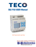
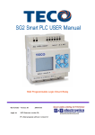
SG2 PLR USER Manual
www.alltronicsperu.com
SG2 Relé Logico Programable
Teléfonos: 628-0810 / 628-0811
Fax: 4627136
Nextel: 832*8591 / 832*7745
WEB www.alltronicsperu.com
Calle Manco Capac 125 Ofic. 102 Magdalena del Mar Lima - Perú
™
1-800-972-0436
WWW.FACTORYMATION.COM
2
Table of Contents
Chapter 1: Getting Started . . . . . . . . . . . . . . . . . . . . . . . . . . . . . . . . . . . . . . . . . . . . .4
Examination Before Installation . . . . . . . . . . . . . . . . . . . . . . . . . . . . . . . . . . . . . . . . . . . . . . . . . . . . . .5
Environmental Precautions . . . . . . . . . . . . . . . . . . . . . . . . . . . . . . . . . . . . . . . . . . . . . . . . . . . . . . . . . .5
SG2 Model Identification . . . . . . . . . . . . . . . . . . . . . . . . . . . . . . . . . . . . . . . . . . . . . . . . . . . . . . . . . . . .5
Quick Start Setup . . . . . . . . . . . . . . . . . . . . . . . . . . . . . . . . . . . . . . . . . . . . . . . . . . . . .6
Chapter 2: Installation . . . . . . . . . . . . . . . . . . . . . . . . . . . . . . . . . . . . . . . . . . . . . . . .12
General Specifications . . . . . . . . . . . . . . . . . . . . . . . . . . . . . . . . . . . . . . . . . . . . . . . . . . . . . . . . . . . . .12
Product Specifications . . . . . . . . . . . . . . . . . . . . . . . . . . . . . . . . . . . . . . . . . . . . . . . . . . . . . . . . . . . . .13
Mounting . . . . . . . . . . . . . . . . . . . . . . . . . . . . . . . . . . . . . . . . . . . . . . . . . . . . . . . . . . . . . . . . . . . . . . . .14
Wiring . . . . . . . . . . . . . . . . . . . . . . . . . . . . . . . . . . . . . . . . . . . . . . . . . . . . . . . . . . . . . . . . . . . . . . . . . . .16
Chapter 3: Program Tools . . . . . . . . . . . . . . . . . . . . . . . . . . . . . . . . . . . . . . . . . . . . .19
PC Programming Software “SG2 Client” . . . . . . . . . . . . . . . . . . . . . . . . . . . . . . . . . . . . . . . . . . . . .19
Memory Cartridge . . . . . . . . . . . . . . . . . . . . . . . . . . . . . . . . . . . . . . . . . . . . . . . . . . . . . . . . . . . . . . . .27
LCD Display and Keypad . . . . . . . . . . . . . . . . . . . . . . . . . . . . . . . . . . . . . . . . . . . . . . . . . . . . . . . . . . .28
www.alltronicsperu.com
Chapter 4: Relay Ladder Logic Programming . . . . . . . . . . . . . . . . . . . . . . . . . . . . .29
Specialty Memory Types . . . . . . . . . . . . . . . . . . . . . . . . . . . . . . . . . . . . . . . . . . . . . . . . . . . . . . . . . . .31
Output Instructions . . . . . . . . . . . . . . . . . . . . . . . . . . . . . . . . . . . . . . . . . . . . . . . . . . . . . . . . . . . . . . .32
Counter Instructions . . . . . . . . . . . . . . . . . . . . . . . . . . . . . . . . . . . . . . . . . . . . . . . . . . . . . . . . . . . . . .34
High Speed Counters (DC Version PLRs Only) . . . . . . . . . . . . . . . . . . . . . . . . . . . . . . . . . . . . . . . .40
Timer Instructions . . . . . . . . . . . . . . . . . . . . . . . . . . . . . . . . . . . . . . . . . . . . . . . . . . . . . . . . . . . . . . . . .42
Real Time Clock (RTC) Instructions . . . . . . . . . . . . . . . . . . . . . . . . . . . . . . . . . . . . . . . . . . . . . . . . . .49
Comparator Instructions . . . . . . . . . . . . . . . . . . . . . . . . . . . . . . . . . . . . . . . . . . . . . . . . . . . . . . . . . . .51
HMI Display Instructions . . . . . . . . . . . . . . . . . . . . . . . . . . . . . . . . . . . . . . . . . . . . . . . . . . . . . . . . . . .53
PWM Output Instruction (DC Transistor Output Models Only) . . . . . . . . . . . . . . . . . . . . . . . . . . .54
Data Link/Remote I/O Instruction (SG2-20Vxx Models Only) . . . . . . . . . . . . . . . . . . . . . . . . . . . . .55
6HFXUHRQOLQHRUGHULQJIURP
6*3/58VHU0DQXDO
SG2 PLR User Manual
,QWHUQDWLRQDO2IILFHZZZEEHOHFFRP
'D\WRQ5RDG32%R[
2WWDZD,/86$
)D[
RUGHUV#EEHOHFFRPVXSSRUW#EEHOHFFRP
(XURSHDQ2IILFHZZZEEHXURSHFRP
:HVWOLQN&RPPHUFLDO3DUN
2UDQPRUH&R*DOZD\,UHODQG
)D[
RUGHUV#EEHXURSHFRPVXSSRUW#EEHXURSHFRP
Chapter 5: Function Block Diagram Programming . . . . . . . . . . . . . . . . . . . . . . . . .57
Coil Block Instruction . . . . . . . . . . . . . . . . . . . . . . . . . . . . . . . . . . . . . . . . . . . . . . . . . . . . . . . . . . . . . .57
Logic Block Instructions . . . . . . . . . . . . . . . . . . . . . . . . . . . . . . . . . . . . . . . . . . . . . . . . . . . . . . . . . . .57
PWM Function Block . . . . . . . . . . . . . . . . . . . . . . . . . . . . . . . . . . . . . . . . . . . . . . . . . . . . . . . . . . . . . .58
SHIFT Function Block . . . . . . . . . . . . . . . . . . . . . . . . . . . . . . . . . . . . . . . . . . . . . . . . . . . . . . . . . . . . .58
AND Logic Block . . . . . . . . . . . . . . . . . . . . . . . . . . . . . . . . . . . . . . . . . . . . . . . . . . . . . . . . . . . . . . . . . .59
AND (Edge) Logic Block . . . . . . . . . . . . . . . . . . . . . . . . . . . . . . . . . . . . . . . . . . . . . . . . . . . . . . . . . . .59
NAND Logic Block . . . . . . . . . . . . . . . . . . . . . . . . . . . . . . . . . . . . . . . . . . . . . . . . . . . . . . . . . . . . . . . .59
NAND (Edge) Logic Block . . . . . . . . . . . . . . . . . . . . . . . . . . . . . . . . . . . . . . . . . . . . . . . . . . . . . . . . . .59
OR Logic . . . . . . . . . . . . . . . . . . . . . . . . . . . . . . . . . . . . . . . . . . . . . . . . . . . . . . . . . . . . . . . . . . . . . . . .60
NOR Logic . . . . . . . . . . . . . . . . . . . . . . . . . . . . . . . . . . . . . . . . . . . . . . . . . . . . . . . . . . . . . . . . . . . . . . .60
XOR Logic . . . . . . . . . . . . . . . . . . . . . . . . . . . . . . . . . . . . . . . . . . . . . . . . . . . . . . . . . . . . . . . . . . . . . . .60
SR Logic Block . . . . . . . . . . . . . . . . . . . . . . . . . . . . . . . . . . . . . . . . . . . . . . . . . . . . . . . . . . . . . . . . . . .60
NOT Logic Block . . . . . . . . . . . . . . . . . . . . . . . . . . . . . . . . . . . . . . . . . . . . . . . . . . . . . . . . . . . . . . . . . .61
Pulse Logic Block . . . . . . . . . . . . . . . . . . . . . . . . . . . . . . . . . . . . . . . . . . . . . . . . . . . . . . . . . . . . . . . . .61
Counter Function Block . . . . . . . . . . . . . . . . . . . . . . . . . . . . . . . . . . . . . . . . . . . . . . . . . . . . . . . . . . .61
Counter Mode 5 . . . . . . . . . . . . . . . . . . . . . . . . . . . . . . . . . . . . . . . . . . . . . . . . . . . . . . . . . . . . . . . . . . .62
Counter Mode 6 . . . . . . . . . . . . . . . . . . . . . . . . . . . . . . . . . . . . . . . . . . . . . . . . . . . . . . . . . . . . . . . . . . .62
High Speed Counter Function Block . . . . . . . . . . . . . . . . . . . . . . . . . . . . . . . . . . . . . . . . . . . . . . . .63
Timer Function Block . . . . . . . . . . . . . . . . . . . . . . . . . . . . . . . . . . . . . . . . . . . . . . . . . . . . . . . . . . . . . .63
RTC Function Block . . . . . . . . . . . . . . . . . . . . . . . . . . . . . . . . . . . . . . . . . . . . . . . . . . . . . . . . . . . . . .65
Analog comparator Function Block . . . . . . . . . . . . . . . . . . . . . . . . . . . . . . . . . . . . . . . . . . . . . . . . .66
www.alltronicsperu.com
6HFXUHRQOLQHRUGHULQJIURP
6*3/58VHU0DQXDO
,QWHUQDWLRQDO2IILFHZZZEEHOHFFRP
'D\WRQ5RDG32%R[
2WWDZD,/86$
)D[
RUGHUV#EEHOHFFRPVXSSRUW#EEHOHFFRP
SG2 PLR User Manual
(XURSHDQ2IILFHZZZEEHXURSHFRP
:HVWOLQN&RPPHUFLDO3DUN
™
2UDQPRUH&R*DOZD\,UHODQG
)D[
RUGHUV#EEHXURSHFRPVXSSRUW#EEHXURSHFRP
4
Chapter 1: Getting Started
Chapter 1: Getting Started
The SG2 PLR is an electronic device. For safety reasons, please carefully read and follow the
paragraphs with "WARNING" or "CAUTION" symbols.They are important safety precautions to be aware
of while transporting, installing, operating, or examining the SG2 Controller.
WARNING: Personal injury may result from improper operation.
CAUTION: The SG2 PLR may be damaged by improper operation.
Precaution for Installation
Compliance with the installation instructions and the user manual is absolutely necessary. Failure to comply could
lead to improper operation, equipment damage or in extreme cases even death, serious bodily injury or considerable
damage to property.
When installing the open-board models, insure that no wiring or foreign materials can fall into the exposed circuits
and components. Damage to equipment, fire, or considerable damage to property could result.
Always switch off power before you wire, connect, install, or remove any module.
The wiring for the SG2 PLR is open and exposed. For the open-board models, all electrical components are exposed.
For this reason, it is recommended the SG2 PLR be installed in an enclosure or cabinet to prevent accidental
contact or exposure to the electrical circuits and components.
Never install the product in an environment beyond the limits specified in this user manual such as high temperature,
humidity, dust, corrosive gas, vibration, etc.
www.alltronicsperu.com
Precaution for Wiring
Improper wiring and installation could lead to death, serious bodily injury or considerable damage to property.
The SG2 PLR should only be installed and wired by properly experienced and certified personnel.
Make sure the wiring of the SG2 PLR meets all applicable regulations and codes including local and national standards
and codes.
Be sure to properly size cables for the required current rating.
Always separate AC wiring, DC wiring with high-frequency switching cycles, and low-voltage signal wiring.
Precaution for Operation
To insure safety with the application of the SG2 PLR, complete functional and safety testing must be conducted.
Only run the SG2 after all testing and confirming safe and proper operation is complete. Any potential faults in the
application should be included in the testing. Failure to do so could lead to improper operation, equipment damage
or in extreme cases even Death, serious bodily injury or considerable damage to property.
When the power is on, never contact the terminals, exposed conductors or electrical components. Failure to comply
could lead to improper operation, equipment damage or in extreme cases even death, serious bodily injury or
considerable damage to property.
It is strongly recommended to add safety protection such as an emergency stop and external interlock circuit in case the
SG2 PLR operation must be shut down immediately.
6HFXUHRQOLQHRUGHULQJIURP
6*3/58VHU0DQXDO
SG2 PLR User Manual
,QWHUQDWLRQDO2IILFHZZZEEHOHFFRP
'D\WRQ5RDG32%R[
2WWDZD,/86$
)D[
RUGHUV#EEHOHFFRPVXSSRUW#EEHOHFFRP
(XURSHDQ2IILFHZZZEEHXURSHFRP
:HVWOLQN&RPPHUFLDO3DUN
2UDQPRUH&R*DOZD\,UHODQG
)D[
RUGHUV#EEHXURSHFRPVXSSRUW#EEHXURSHFRP
Chapter 1: Getting Started
5
Examination Before Installation
Every SG2 PLR has been fully tested and examined before shipment. Please carry out the following
examination procedures after unpacking your SG2 Programmable Logic Relay.
• Check to see if the model number of the SG2 matches the model number that you ordered.
• Check to see whether any damage occurred to the SG2 during shipment. Do not connect the SG2 PLR to the power
supply if there is any sign of damage.
Contact FactoryMation if you find any abnormal conditions as mentioned above.
Environmental Precautions
The installation site of the SG2 PLR is very important. It relates directly to the functionality and the life
span of your SG2 . Please carefully choose an installation site that meets the following requirements:
• Mount the unit vertically
• Environment temperature: 32°F - 131°F (0°C - 55°C)
• Avoid placing SG2 close to any heating equipment
• Avoid dripping water, condensation, or humid environment
• Avoid direct sunlight
• Avoid oil, grease, and gas
• Avoid contact with corrosive gases and liquids
• Prevent foreign dust, flecks, or metal scraps from contacting the SG2 PLR
• Avoid electric-magnetic interference (soldering or power machinery)
• Avoid excessive vibration; if vibration cannot be avoided, an anti-rattle mounting device should be installed to reduce
vibration.
www.alltronicsperu.com
SG2 Model Identification
SG2 –
20
H
R
–
A
Input Power
Controller Type
D = DC Powered
A = AC Powered
I/O Count
8 = 8 points (expansion modules)
10 = 10 I/O points
12 = 12 I/O points
20 = 20 I/O points
Output Type
R = Relay
T = Transistor
Form Factor
H = Encased w/ LCD & Keypad
V = Encased w/LCD, Keypad & RS-485 Communication
C = Bareboard
E = Expansion
Teléfonos: 628-0810 / 628-0811
Fax: 4627136
Nextel: 832*8591 / 832*7745
WEB www.alltronicsperu.com
Calle Manco Capac 125 Ofic. 102 Magdalena del Mar Lima - Perú
6HFXUHRQOLQHRUGHULQJIURP
6*3/58VHU0DQXDO
,QWHUQDWLRQDO2IILFHZZZEEHOHFFRP
'D\WRQ5RDG32%R[
2WWDZD,/86$
)D[
RUGHUV#EEHOHFFRPVXSSRUW#EEHOHFFRP
SG2 PLR User Manual
(XURSHDQ2IILFHZZZEEHXURSHFRP
:HVWOLQN&RPPHUFLDO3DUN
™
2UDQPRUH&R*DOZD\,UHODQG
)D[
RUGHUV#EEHXURSHFRPVXSSRUW#EEHXURSHFRP
6
Chapter 1: Getting Started
Quick Start Setup
This section is a simple 6-step guide to connecting, programming and operating your new SG2
Programmable Logic Relay. This is not intended to be the complete instructions for programming and
installation of your system. Many steps refer to other sections in the manual for more detailed
information.
1. Install SG2 Client Software
Install the SG2 Client Software from CD or from the free internet download.
www.alltronicsperu.com
2. Connect Power to SG2 PLR
Connect power to the PLR using the below wiring diagrams for AC or DC supply for the applicable
models. See “Chapter 2: Installation” for complete wiring and installation instructions
AC (100-240V)
DC (24V)
L
1
24V
+
2
100...240V
50/60 Hz
-
3
N
-
+
L N
DC ..V
AC ..V
Fuse (2A)
Surge absorber (36V DC)
Surge absorber (400V AC)
6HFXUHRQOLQHRUGHULQJIURP
6*3/58VHU0DQXDO
SG2 PLR User Manual
,QWHUQDWLRQDO2IILFHZZZEEHOHFFRP
'D\WRQ5RDG32%R[
2WWDZD,/86$
)D[
RUGHUV#EEHOHFFRPVXSSRUW#EEHOHFFRP
(XURSHDQ2IILFHZZZEEHXURSHFRP
:HVWOLQN&RPPHUFLDO3DUN
2UDQPRUH&R*DOZD\,UHODQG
)D[
RUGHUV#EEHXURSHFRPVXSSRUW#EEHXURSHFRP
Chapter 1: Getting Started
7
3. Connect Programming Cable
Remove the plastic connector cover from the SG2 using a flathead screwdriver as shown in the figure
below. Insert the plastic connector end of the programming cable into the SG2 PLR as shown in the
figure below. Connect the opposite end of the cable to an RS232C serial port on the computer.
4. Establish Communication
a.
Open the SG2 Client software and select “New Ladder Document” as shown below.
b.
Select “Operation/Link Com Port…” as shown
www.alltronicsperu.com
6HFXUHRQOLQHRUGHULQJIURP
6*3/58VHU0DQXDO
,QWHUQDWLRQDO2IILFHZZZEEHOHFFRP
'D\WRQ5RDG32%R[
2WWDZD,/86$
)D[
RUGHUV#EEHOHFFRPVXSSRUW#EEHOHFFRP
SG2 PLR User Manual
(XURSHDQ2IILFHZZZEEHXURSHFRP
:HVWOLQN&RPPHUFLDO3DUN
™
2UDQPRUH&R*DOZD\,UHODQG
)D[
RUGHUV#EEHXURSHFRPVXSSRUW#EEHXURSHFRP
8
Chapter 1: Getting Started
c.
Select the correct Com Port number where the programming cable is connected to the computer
then press the “Link” button.
d.
The SG2 Client will then begin to detect the connected PLR to complete it’s connection as shown
below.
5. Write simple program
www.alltronicsperu.com
a.
Write a simple one rung program by clicking on the leftmost cell at line 001 of the programming
grid, then click on the “M” contact icon on the ladder toolbar, as shown below. Select M1 and
press the OK button. See Chapter 4: Ladder Programming instructions for complete instruction
set definitions.
Note: If the ladder toolbar is not visible at the bottom of the screen, select View>Ladder Toolbar from the
menu to enable.
6HFXUHRQOLQHRUGHULQJIURP
6*3/58VHU0DQXDO
SG2 PLR User Manual
,QWHUQDWLRQDO2IILFHZZZEEHOHFFRP
'D\WRQ5RDG32%R[
2WWDZD,/86$
)D[
RUGHUV#EEHOHFFRPVXSSRUW#EEHOHFFRP
(XURSHDQ2IILFHZZZEEHXURSHFRP
:HVWOLQN&RPPHUFLDO3DUN
2UDQPRUH&R*DOZD\,UHODQG
)D[
RUGHUV#EEHXURSHFRPVXSSRUW#EEHXURSHFRP
Chapter 1: Getting Started
b.
9
Use the “A” key on your keyboard (or the “A” icon from the ladder toolbar) to draw the horizontal
circuit line from the M contact to the right most cell, as shown below.
www.alltronicsperu.com
c.
Select the “Q” coil icon from the ladder toolbar and drop it on the right most cell. Select Q1 from
the dialog and press OK as shown below. See Chapter 4: Ladder Programming instructions for
complete instruction set definitions.
6HFXUHRQOLQHRUGHULQJIURP
6*3/58VHU0DQXDO
,QWHUQDWLRQDO2IILFHZZZEEHOHFFRP
'D\WRQ5RDG32%R[
2WWDZD,/86$
)D[
RUGHUV#EEHOHFFRPVXSSRUW#EEHOHFFRP
SG2 PLR User Manual
(XURSHDQ2IILFHZZZEEHXURSHFRP
:HVWOLQN&RPPHUFLDO3DUN
™
2UDQPRUH&R*DOZD\,UHODQG
)D[
RUGHUV#EEHXURSHFRPVXSSRUW#EEHXURSHFRP
10
Chapter 1: Getting Started
d.
Test the simple program. From the Operation menu, select the Write function and write the
program to the connected PLR as shown below.
e.
Select the RUN icon from the toolbar, and select “No” when the pop-up message asks “Do you
want to read program from module?”, as shown below.
www.alltronicsperu.com
6HFXUHRQOLQHRUGHULQJIURP
6*3/58VHU0DQXDO
SG2 PLR User Manual
,QWHUQDWLRQDO2IILFHZZZEEHOHFFRP
'D\WRQ5RDG32%R[
2WWDZD,/86$
)D[
RUGHUV#EEHOHFFRPVXSSRUW#EEHOHFFRP
(XURSHDQ2IILFHZZZEEHXURSHFRP
:HVWOLQN&RPPHUFLDO3DUN
2UDQPRUH&R*DOZD\,UHODQG
)D[
RUGHUV#EEHXURSHFRPVXSSRUW#EEHXURSHFRP
Chapter 1: Getting Started
f.
11
From the Input Status dialog, click on M1 to activate the contact M1 which will turn ON the Output
Q1, as shown below. The highlighted circuit will show active and the first Output (Q1) on the
connected PLR will be ON. See Chapter 3: Programming Tools for more detailed software
information.
www.alltronicsperu.com
6HFXUHRQOLQHRUGHULQJIURP
6*3/58VHU0DQXDO
,QWHUQDWLRQDO2IILFHZZZEEHOHFFRP
'D\WRQ5RDG32%R[
2WWDZD,/86$
)D[
RUGHUV#EEHOHFFRPVXSSRUW#EEHOHFFRP
SG2 PLR User Manual
(XURSHDQ2IILFHZZZEEHXURSHFRP
:HVWOLQN&RPPHUFLDO3DUN
™
2UDQPRUH&R*DOZD\,UHODQG
)D[
RUGHUV#EEHXURSHFRPVXSSRUW#EEHXURSHFRP
12
Chapter 2: Installation
Chapter 2: Installation
General Specifications
SG2 is a miniature smart PLR (Programmable Logic Relay) with a maximum of 44 I/O points and can
be programmed in Relay Ladder Logic or FBD (Function Block Diagram) program. The SG2 can
expand to its maximum I/O count by adding 3 groups of 4-input X 4-output modules.
Power Supply
Input Power Voltage Range
Power Consumption
Wire Size (all terminals)
Discrete Inputs
DC Models: 20.4-28.8V
AC Models: 85-265V
24VDC: 10-point, 90mA
20-point: 150mA
100-240VAC: 90mA
26 to 14 AWG
Programming
Programming languages
Ladder/Function Block
Program Memory
200 Lines or 99 Function Blocks
Programming storage media
Flash
Execution Speed
10ms/cycle
LCD Display
4 lines x 12 characters
Timers
Maximum Number
15
Timing ranges
0.01s–9999min
Current consumption
Input Signal ”OFF” Threshold
Input Signal ”ON” Threshold
4mA @12VDC
3.2mA @24VDC
1.3mA @100-240VAC
< 5VDC; < 40VAC
Transistor device compatibility
> 15VDC; > 79VAC
DC: 5ms
240VAC: 50ms
120VAC: 90ms
DC: 3ms
240VAC: 50ms
120VAC: 90ms
PNP, 3-wire device only
High Speed Input frequency
1kHz
Standard Input frequency
< 40 Hz
Input On delay
Input Off Delay
www.alltronicsperu.com
Required protection
Inverse voltage protection required
Analog Inputs
Counters
Maximum Number
15
Resolution
Highest count
999999
Resolution
1
Voltage Range acceptable
RTC (Real Time Clock)
Number available
15
Resolution
1min
Time span available
week, year, month, day, hour, min
Compare Instructions (Analog, Timer, or Counter Values)
10 bit
Analog input: 0-10VDC,
24VDC when used as discrete input
Input Signal ”OFF” Threshold
< 5VDC (as 24VDC discreet input)
Input Signal ”ON” Threshold
> 9.8VDC (as 24VDC discreet input)
Isolation
None
Short circuit protection
Yes
Total number available
A1-A8
Number available
15
Compare versus other inputs
Timer, Counter, or Numeric values
Relay Outputs
Contact material
Ag Alloy
Enclosure Type
IP20
Current rating
8A
Maximum Vibration
1G according to IEC60068-2-6
HP rating
Operating Temperature Range
32° to 131°F (0° to 55°C)
Maximum Load
Storage Temperature Range
-40° to 158°F (-40° to 70°C)
Maximum Humidity
90% (Relative, non-condensing)
0.075mm amplitude
1.0g acceleration
10-point: 230g
8-point:190g
20-point: 345g
cUL , CE, UL
Maximum operating time
1/3HP@120V 1/2HP@250V
Resistive: 8A/point
Inductive: 4A/point
15ms (normal condition)
Life expectancy (rated load)
100k operations
Minimum load
16.7mA
Environmental
Vibration
Weight
Agency Approvals
Transistor Outputs
PWM max. output frequency
Voltage specification
10-28.8VDC
Current capacity
1A
Resistive: 0.5A/point
Inductive: 0.3A/point
0.2mA
Maximum Load
Minimum Load
6HFXUHRQOLQHRUGHULQJIURP
6*3/58VHU0DQXDO
SG2 PLR User Manual
0.5kHz (1ms on,1ms off)
Standard max. output frequency 100Hz
,QWHUQDWLRQDO2IILFHZZZEEHOHFFRP
'D\WRQ5RDG32%R[
2WWDZD,/86$
)D[
RUGHUV#EEHOHFFRPVXSSRUW#EEHOHFFRP
(XURSHDQ2IILFHZZZEEHXURSHFRP
:HVWOLQN&RPPHUFLDO3DUN
2UDQPRUH&R*DOZD\,UHODQG
)D[
RUGHUV#EEHXURSHFRPVXSSRUW#EEHXURSHFRP
Chapter 2: Installation
13
Product Specifications
Part #
Input Power
Inputs
Outputs
Display
6 DC, 2 Analog
4 Relay
SG2-12HR-D
✓
6 DC, 2 Analog
4 Trans.
SG2-12HT-D
✓
8 DC, 4 Analog
8 Relay
SG2-20HR-D
✓
24 VDC
8 DC, 4 Analog
8 Trans.
SG2-20HT-D
✓
8 DC, 4 Analog
8 Relay
SG2-20VR-D
✓
8 DC, 4 Analog
8 Trans.
SG2-20VT-D
✓
6 AC
4 Relay
SG2-10HR-A
✓
85-240 VAC
12 AC
8 Relay
SG2-20HR-A
✓
Expansion Modules
4 DC
4 Relay
N/A
SG2-8ER-D
24VDC
4 DC
4 Trans.
N/A
SG2-8ET-D
85-240VAC
4 AC
4 Relay
N/A
SG2-8ER-A
12-24 VDC
4 Analog
N/A
N/A
SG2-4AI
24 VDC
Communications Module, RS-485 MODBUS-RTU
SG2-MODBUS
OEM “Blind” Models, No Keypad, No Display
6 DC, 2 Analog
4 Relay
X
SG2-12KR-D
24VDC
8 DC, 4 Analog
8 Relay
X
SG2-20KR-D
6 AC
4 Relay
X
SG2-10KR-A
85-240VAC
12 AC
8 Relay
X
SG2-20KR-A
OEM “Bareboard” Models, No Keypad, No Display, No Expansion
6 DC, 2 Analog
4 Relay
X
SG2-12CR-D
24VDC
8 DC, 4 Analog
8 Relay
X
SG2-20CR-D
6
AC
4
Relay
X
SG2-10CR-A
85-240VAC
12
AC
8
Relay
X
SG2-20CR-A
Accessories
SG2 Programming Cable
SG2-PL01
SG2 Memory cartridge
SG2-PM05
SG2 Programming software. Available on CD or FREE via download from Web
SG2-SW
RS-485 Communications
Max I/O*
N/A
36
N/A
36
N/A
44
N/A
44
Built-in MODBUS
44
Built-in MODBUS
44
N/A
34
N/A
44
N/A
N/A
N/A
N/A
N/A
N/A
N/A
N/A
www.alltronicsperu.com
N/A
12
N/A
20
N/A
10
N/A
20
N/A
12
N/A
20
N/A
10
N/A
20
Teléfonos: 628-0810 / 628-0811
Fax: 4627136
Nextel: 832*8591 / 832*7745
WEB www.alltronicsperu.com
Calle Manco Capac 125 Ofic. 102 Magdalena del Mar Lima - Perú
6HFXUHRQOLQHRUGHULQJIURP
6*3/58VHU0DQXDO
,QWHUQDWLRQDO2IILFHZZZEEHOHFFRP
'D\WRQ5RDG32%R[
2WWDZD,/86$
)D[
RUGHUV#EEHOHFFRPVXSSRUW#EEHOHFFRP
SG2 PLR User Manual
(XURSHDQ2IILFHZZZEEHXURSHFRP
:HVWOLQN&RPPHUFLDO3DUN
™
2UDQPRUH&R*DOZD\,UHODQG
)D[
RUGHUV#EEHXURSHFRPVXSSRUW#EEHXURSHFRP
14
Chapter 2: Installation
Mounting
DIN-rail Mounting
The SG2 PLR should always be mounted vertically. Press the slots on the
back of the SG2 and expansion module plug CONNECTOR onto the rail
until the plastic clamps hold the rails in place. Then connect the expansion
module and CONNECTOR with the Master (press the PRESS-BUTTON
simultaneously)
1
www.alltronicsperu.com
2
2
1
CLIC
CONNECTOR
+
-
DC 24V
I1 I2
I3
I4
I5
I6 A1 A2
Input 8 x DC(A1,A2 0~10V)
Input
4×AC
L
X1 X2 X3 X4
PRESS-BUTTON
N AC 100~240V
Run
SG2-8ER-A
SG2-12HR-D
Output 4 x Relay / 8A
Output 4 x Relay / 8A
Q1
Q2
Y1
Q3
Q4
6HFXUHRQOLQHRUGHULQJIURP
6*3/58VHU0DQXDO
SG2 PLR User Manual
Y3
Y2
Din Rail
Y4
,QWHUQDWLRQDO2IILFHZZZEEHOHFFRP
'D\WRQ5RDG32%R[
2WWDZD,/86$
)D[
RUGHUV#EEHOHFFRPVXSSRUW#EEHOHFFRP
(XURSHDQ2IILFHZZZEEHXURSHFRP
:HVWOLQN&RPPHUFLDO3DUN
2UDQPRUH&R*DOZD\,UHODQG
)D[
RUGHUV#EEHXURSHFRPVXSSRUW#EEHXURSHFRP
Chapter 2: Installation
15
It is recommended to apply a DIN-rail end clamp to hold the SG2 in place.
+
-
DC 24V
I1 I2
I3
I4
I5
I6 A1 A2
X1 X2 X3 X4
Input
4hAC
L
Input 8 x DC(A1,A2 0~10V)
Mounting Clip
N AC 100~240V
Run
SG2-8ER-A
SG2-12HR-D
Output 4 x Relay / 8A
Output 4 x Relay / 8A
Q1
Y1
Q2
Q3
Q4
Din Rail
Y2
Y3
Y4
www.alltronicsperu.com
Direct Mounting
Use M4 screws to direct
mount the SG2 as shown.
For direct installation of the
expansion module, slide the
expansion module and
connect with the Master
after the Master is fixed.
+
-
I1
I2
I3
I4
I5
I6 A1 A2
DC24V INPUT8xDC(A1,A2 0~10V)
M4X20(#8x32)
SG2-12HR-D
OUTPUT4xRELAY/8A
Q1
+
-
DC 24V
I1 I2
I3
I4
I5
I6 A1 A2
Input
4×AC
L
Input 8 x DC(A1,A2 0~10V)
Q2
Q3
Q4
X1 X2 X3 X4
N AC 100~240V
M4X20(#8x32)
1
2
Run
3
SG2-8ER-A
SG2-12HR-D
Output 4 x Relay / 8A
CONNECTOR
Output 4 x Relay / 8A
Q1
Q2
Y1
Q3
Q4
Y3
Y2
Y4
6HFXUHRQOLQHRUGHULQJIURP
6*3/58VHU0DQXDO
SG2 PLR User Manual
,QWHUQDWLRQDO2IILFHZZZEEHOHFFRP
'D\WRQ5RDG32%R[
2WWDZD,/86$
)D[
RUGHUV#EEHOHFFRPVXSSRUW#EEHOHFFRP
SG2 PLR User Manual
(XURSHDQ2IILFHZZZEEHXURSHFRP
:HVWOLQN&RPPHUFLDO3DUN
™
2UDQPRUH&R*DOZD\,UHODQG
)D[
RUGHUV#EEHXURSHFRPVXSSRUW#EEHXURSHFRP
16
Chapter 2: Installation
Wiring
WARNING: The I/O signal cables should not be routed parallel to the power cable, or in the same cable trays to avoid
the signal interference.
To avoid a short circuit on the load side, it is recommended to connect a fuse between each output terminals and loads.
Wire size and Terminal Torque
2
mm
0.14...1.5
0.14...0.75
0.14...2.5
0.14...2.5
0.14...1.5
AWG
26...16
26...18
26...14
26...14
26...16
C
C
Ø3.5
(0.14in)
Nm
0.6
lb-in
5.4
0-10V Analog
10/12-point Versions
1
2
www.alltronicsperu.com
Fuse (2A)
Surge absorber (36V DC)
Surge absorber (400V AC)
Fuse or short circuit Protective Device
+-
Power Supply and Input Terminals
1
L
24V
100...240V
50/60 Hz
+
2
3
N
-
L N
AC ..V
AC (100-240V)
I1 I2
I3
I4
I5
+
I6
DC (24V)
Input ......
Output Terminals
Q1
L/+
or 12...125V
N/-
Q2
-
DC ..V
I1 I2
I3
I4
I5
I6 A1 A2
+
-
+
Input ......
OUTPUT 4 x TR / 0.5A
Output 4 x Relay / 8A
12...240V
50/60 Hz
A1 A2
1
Q3
+
Q1
Q4
4
+
24V
-
+
Q2
-
Q3
Q4
-
4
or
12V
-
12...240V 50/60 Hz
6HFXUHRQOLQHRUGHULQJIURP
6*3/58VHU0DQXDO
SG2 PLR User Manual
,QWHUQDWLRQDO2IILFHZZZEEHOHFFRP
'D\WRQ5RDG32%R[
2WWDZD,/86$
)D[
RUGHUV#EEHOHFFRPVXSSRUW#EEHOHFFRP
(XURSHDQ2IILFHZZZEEHXURSHFRP
:HVWOLQN&RPPHUFLDO3DUN
2UDQPRUH&R*DOZD\,UHODQG
)D[
RUGHUV#EEHXURSHFRPVXSSRUW#EEHXURSHFRP
Chapter 2: Installation
17
20-point Versions
Fuse (2A)
0-10V Analog
Surge absorber (36V DC)
1
Surge absorber (400V AC)
2
3
4
Fuse or short circuit Protective Device
Power Supply and Input Terminals
L
1
+
3
N
1
+-
A1 A3
A2 A4
2
L N
I1 I2
I3
I4
I5
I6
I7
I8
I9
-
IA IB IC
DC (24V)
AC (100-240V)
AC ..V
INPUT ......
+ -
I1 I2
I3
DC ..V
I4
I5
I6
I7
I8
A1 A2 A3 A4
INPUT ......
Run
Run
Output Terminals
www.alltronicsperu.com
Output 8 x Relay / 8A
Q1
12...240V
50/60 Hz
L/+
or 12...125V
N/-
Q2
OUTPUT 8 x TR / 0.5A
Q3
Q4
Q5
Q6
Q7
+
Q8
Q1
-
5
4
24V
or
12V
U
+
+
Q2
-
+
Q3
-
+
Q4
-
+
Q5
-
+
Q6
-
+
Q7
-
+
Q8
-
5
4
U
-
Sensor Connection
3-wire, PNP only
YES
+
-
DC V
I1 I2 I3
I4 I5 I6 A1 A2
Input
2-wire
NO
6HFXUHRQOLQHRUGHULQJIURP
6*3/58VHU0DQXDO
,QWHUQDWLRQDO2IILFHZZZEEHOHFFRP
'D\WRQ5RDG32%R[
2WWDZD,/86$
)D[
RUGHUV#EEHOHFFRPVXSSRUW#EEHOHFFRP
SG2 PLR User Manual
(XURSHDQ2IILFHZZZEEHXURSHFRP
:HVWOLQN&RPPHUFLDO3DUN
™
2UDQPRUH&R*DOZD\,UHODQG
)D[
RUGHUV#EEHXURSHFRPVXSSRUW#EEHXURSHFRP
18
Chapter 2: Installation
DATA LINK OR REMOTE I/O LINK
The power supply and the I/O supply should share the same power source.
Only short circuit the first and the last module.
In accordance to EIA RS-485 standard, DATA LINK can connect Max.8 Modules (ID:1-8). REMOTE I/O
can only connect 2 modules (MASTER & SLAVE).
www.alltronicsperu.com
�
A1 A2 A3 A4
S
�
A
B
A1 A2 A3 A4
RS485
S
A
B
A1 A2 A3 A4
RS485
6HFXUHRQOLQHRUGHULQJIURP
6*3/58VHU0DQXDO
SG2 PLR User Manual
S
A
B
RS485
,QWHUQDWLRQDO2IILFHZZZEEHOHFFRP
'D\WRQ5RDG32%R[
2WWDZD,/86$
)D[
RUGHUV#EEHOHFFRPVXSSRUW#EEHOHFFRP
(XURSHDQ2IILFHZZZEEHXURSHFRP
:HVWOLQN&RPPHUFLDO3DUN
2UDQPRUH&R*DOZD\,UHODQG
)D[
RUGHUV#EEHXURSHFRPVXSSRUW#EEHXURSHFRP
Chapter 3: Program Tools
19
Chapter 3: Program Tools
PC Programming Software “SG2 Client”
The SG2 Client programming software provides two edit modes, Ladder Logic and Function Block
Diagram (FBD). The SG2 Client software includes the following features:
1. Easy and convenient program creation and editing.
2. Programs can be saved on a computer for archiving and reuse. Programs can also be uploaded directly from an
SG2 and saved or edited.
3. Enables users to print programs for reference and review.
4. The Simulation Mode allows users to run and test their program before it is loaded to the controller.
5. Real-time communication allows the user to monitor and force I/O on the SG2 PLR operation during RUN mode.
Installing the Software
Install the SG2 Client Software from CD or from the free internet download at www.factorymation.com
www.alltronicsperu.com
Connecting the Software
Remove the plastic connector cover from SG2 using a flathead screwdriver as shown in the figure
below. Insert the plastic connector end of the programming cable into the SG2 PLR as shown in the
figure below. Connect the opposite end of the cable to an RS232C serial port on the computer.
Start Screen
Run the SG2 Client software and the following Start screen will be displayed. From this screen, you can
perform the following functions
6HFXUHRQOLQHRUGHULQJIURP
6*3/58VHU0DQXDO
,QWHUQDWLRQDO2IILFHZZZEEHOHFFRP
'D\WRQ5RDG32%R[
2WWDZD,/86$
)D[
RUGHUV#EEHOHFFRPVXSSRUW#EEHOHFFRP
SG2 PLR User Manual
(XURSHDQ2IILFHZZZEEHXURSHFRP
:HVWOLQN&RPPHUFLDO3DUN
™
2UDQPRUH&R*DOZD\,UHODQG
)D[
RUGHUV#EEHXURSHFRPVXSSRUW#EEHXURSHFRP
20
Chapter 3: Program Tools
New Ladder Program
Select File-->New-->New LAD to enter the
development environment for a new Ladder
program.
New FBD Program
Select File-->New-->New FBD to enter the
development environment for a new FBD
(Function Block Diagram) program.
Open Existing File
Select File-->Open to choose the type of file
to open (Ladder or FBD), and choose the
desired program file, and then click Open.
Ladder Logic Programming
Environment
The Ladder Logic Programming Environment
includes all the functions for programming and
testing the SG2 PLR using the Ladder Logic programming language. To begin a new program select
File-->New--> and select the desired model of SG2, and the number of connected expansion units if
applicable, as shown below.
www.alltronicsperu.com
6HFXUHRQOLQHRUGHULQJIURP
6*3/58VHU0DQXDO
SG2 PLR User Manual
,QWHUQDWLRQDO2IILFHZZZEEHOHFFRP
'D\WRQ5RDG32%R[
2WWDZD,/86$
)D[
RUGHUV#EEHOHFFRPVXSSRUW#EEHOHFFRP
(XURSHDQ2IILFHZZZEEHXURSHFRP
:HVWOLQN&RPPHUFLDO3DUN
2UDQPRUH&R*DOZD\,UHODQG
)D[
RUGHUV#EEHXURSHFRPVXSSRUW#EEHXURSHFRP
Chapter 3: Program Tools
21
Menus, Icons and Status Displays
The Ladder programming environment includes the following Menus, Icons and Status Displays
1. Menu bar – Five menu selections for program development and retrieval, editing, communication to connected
controllers, configuration of special functions and viewing preference selections.
2. Main Toolbar – (From Left to Right)
Icons for a New program, opening a program, and printing
Icons for Keypad, Ladder view, HMI/Text editing and Symbol (comments) editing.
Icons for Monitor, Simulator, Controller Mode changes (Run, Stop, and Quit), and Read/Write programs to/from the
PLR.
3. Usage List – List for all memory types and addresses used with the current open program. Used addresses are
designated by a “*” symbol below each address.
4. Amount of free programming memory available.
5. Current Mode – operation mode of the controller, or simulator, from the connected PC.
6. Ladder Toolbar – Icons for selecting and entering all available Ladder Logic instructions.
7. Status Bar – Status of current open project and connected PLR.
www.alltronicsperu.com
6HFXUHRQOLQHRUGHULQJIURP
6*3/58VHU0DQXDO
,QWHUQDWLRQDO2IILFHZZZEEHOHFFRP
'D\WRQ5RDG32%R[
2WWDZD,/86$
)D[
RUGHUV#EEHOHFFRPVXSSRUW#EEHOHFFRP
SG2 PLR User Manual
(XURSHDQ2IILFHZZZEEHXURSHFRP
:HVWOLQN&RPPHUFLDO3DUN
™
2UDQPRUH&R*DOZD\,UHODQG
)D[
RUGHUV#EEHXURSHFRPVXSSRUW#EEHXURSHFRP
22
Chapter 3: Program Tools
Programming
The SG2 Client software can be programmed by either drag-and-drop of instructions or by using
keyboard entry commands. Below is an example of some common methods of entering programming
instructions.
www.alltronicsperu.com
The “A” and “L” keys or icons are used to complete parallel and serial circuits. The rightmost column is
for output coils.
6HFXUHRQOLQHRUGHULQJIURP
6*3/58VHU0DQXDO
SG2 PLR User Manual
,QWHUQDWLRQDO2IILFHZZZEEHOHFFRP
'D\WRQ5RDG32%R[
2WWDZD,/86$
)D[
RUGHUV#EEHOHFFRPVXSSRUW#EEHOHFFRP
(XURSHDQ2IILFHZZZEEHXURSHFRP
:HVWOLQN&RPPHUFLDO3DUN
2UDQPRUH&R*DOZD\,UHODQG
)D[
RUGHUV#EEHXURSHFRPVXSSRUW#EEHXURSHFRP
Chapter 3: Program Tools
23
Simulation Mode
The SG2 Client software includes a built-in simulator to test and debug programs easily without the need
for downloading to a controller. To activate simulation mode, simply press the red RUN icon. The
program below is shown in simulation mode, identifying the significant available features.
www.alltronicsperu.com
Establish Communication
The following is the simple procedure for establishing communication between the connected PC and
the SG2 PLR.
a.
Select “Operation/Link Com Port…” as shown below.
6HFXUHRQOLQHRUGHULQJIURP
6*3/58VHU0DQXDO
,QWHUQDWLRQDO2IILFHZZZEEHOHFFRP
'D\WRQ5RDG32%R[
2WWDZD,/86$
)D[
RUGHUV#EEHOHFFRPVXSSRUW#EEHOHFFRP
SG2 PLR User Manual
(XURSHDQ2IILFHZZZEEHXURSHFRP
:HVWOLQN&RPPHUFLDO3DUN
™
2UDQPRUH&R*DOZD\,UHODQG
)D[
RUGHUV#EEHXURSHFRPVXSSRUW#EEHXURSHFRP
24
Chapter 3: Program Tools
b. Select the correct Com Port number where the programming cable is connected to the computer then
press the “Link” button.
c. The SG2 Client software will then begin to detect the connected PLR to complete it’s connection as
shown below.
Writing Program to PLR
www.alltronicsperu.com
From the Operation menu, select the Write function and write the program to the connected PLR as
shown below.
6HFXUHRQOLQHRUGHULQJIURP
6*3/58VHU0DQXDO
SG2 PLR User Manual
,QWHUQDWLRQDO2IILFHZZZEEHOHFFRP
'D\WRQ5RDG32%R[
2WWDZD,/86$
)D[
RUGHUV#EEHOHFFRPVXSSRUW#EEHOHFFRP
(XURSHDQ2IILFHZZZEEHXURSHFRP
:HVWOLQN&RPPHUFLDO3DUN
2UDQPRUH&R*DOZD\,UHODQG
)D[
RUGHUV#EEHXURSHFRPVXSSRUW#EEHXURSHFRP
Chapter 3: Program Tools
25
Operation menu
The Operation menu, includes several system configuration functions for both online and offline setup.
The following explains the details of each function.
Monitor – Online function for runtime monitor and editing when connected to a controller
Simulator – Offline function for testing and debugging a program.
Run-Stop-Quit – Mode change selections for both runtime editing and simulation mode.
Read-Write – Reading and writing programs to and from a connected PLR.
RTC Set – Online function for setup of the Real-time clock/calendar (see dialog below)
Password – Set a password for accessing the current program after upload to the PLR
Language – Change software language
Module System Set – Dialog for changing important system setup functions including Module ID,
Remote I/O preferences, Expansion I/O settings, and Retentive memory preferences (Keeping) for (C )
Counters, (M) Auxiliary Coils, and the LCD Backlight.
www.alltronicsperu.com
Online Monitoring/Editing
The SG2 Client software allows for online monitoring of the currently running program during runtime.
Additional online functions include, I/O forcing, and Mode changes (Run/Stop/Quit).
Note: The SG2 Client software does not support runtime logic editing changes. All logic edits to contacts, coils,
timers/counters, and circuit connecting lines must be written to the connected PLR while in Stop mode.
6HFXUHRQOLQHRUGHULQJIURP
6*3/58VHU0DQXDO
,QWHUQDWLRQDO2IILFHZZZEEHOHFFRP
'D\WRQ5RDG32%R[
2WWDZD,/86$
)D[
RUGHUV#EEHOHFFRPVXSSRUW#EEHOHFFRP
SG2 PLR User Manual
(XURSHDQ2IILFHZZZEEHXURSHFRP
:HVWOLQN&RPPHUFLDO3DUN
™
2UDQPRUH&R*DOZD\,UHODQG
)D[
RUGHUV#EEHXURSHFRPVXSSRUW#EEHXURSHFRP
26
Chapter 3: Program Tools
Program Documentation
The SG2 Client software includes the ability to document a program using Symbols and Line
Comments. Symbols are used to label each I/O address up to a length of 12 characters. Line
Comments are used to document sections of a program. Each Line Comment can have up to 4 lines
with each line containing up to 50 characters in length. Below are examples of entering Symbols and
Line Comments.
Symbol
The Symbol editing environment can be access through the menu using the Edit>Symbol… selection or
using the symbol icon on the main toolbar shown below.
The Symbol editing environment allows for documenting all the contact and coil memory types, and
selecting display modes as shown below.
www.alltronicsperu.com
Line Comments
6HFXUHRQOLQHRUGHULQJIURP
6*3/58VHU0DQXDO
SG2 PLR User Manual
,QWHUQDWLRQDO2IILFHZZZEEHOHFFRP
'D\WRQ5RDG32%R[
2WWDZD,/86$
)D[
RUGHUV#EEHOHFFRPVXSSRUW#EEHOHFFRP
(XURSHDQ2IILFHZZZEEHXURSHFRP
:HVWOLQN&RPPHUFLDO3DUN
2UDQPRUH&R*DOZD\,UHODQG
)D[
RUGHUV#EEHXURSHFRPVXSSRUW#EEHXURSHFRP
Chapter 3: Program Tools
27
The Line Comment editor is accessed by clicking the “N” icon on the Ladder Toolbar. After clicking on
the “N” icon, to drag the line number you want to comment and release, then type the desired comments
and press OK.
www.alltronicsperu.com
Memory Cartridge (sold separately)
The optional PM05 memory cartridge is used to easily transfer programs from one PLR to another. The
PM05 memory cartridge plugs into the same connector as the programming cable (see procedure below).
READ
WRITE
1. Remove the plastic connector cover from SG2 using a flathead screwdriver as shown in the figure above.
2. Insert the PM05 memory cartridge onto the connector as shown above.
3. From the display keypad on the face of the SG2 PLR, select either WRITE (to PM05) or READ (from PM05) to
transfer the program to or from the PLR to the PM05 memory cartridge.
6HFXUHRQOLQHRUGHULQJIURP
6*3/58VHU0DQXDO
,QWHUQDWLRQDO2IILFHZZZEEHOHFFRP
'D\WRQ5RDG32%R[
2WWDZD,/86$
)D[
RUGHUV#EEHOHFFRPVXSSRUW#EEHOHFFRP
SG2 PLR User Manual
(XURSHDQ2IILFHZZZEEHXURSHFRP
:HVWOLQN&RPPHUFLDO3DUN
™
2UDQPRUH&R*DOZD\,UHODQG
)D[
RUGHUV#EEHXURSHFRPVXSSRUW#EEHXURSHFRP
28
Chapter 3: Program Tools
LCD Display and Keypad
Most SG2 CPU units include the built-in LCD Display and Keypad. The keypad and display are most
often used for changing timer/counter setpoints, controller mode changes (Run/Stop),
uploading/downloading to the PM05 memory cartridge, and updating the RTC (Real Time
Clock/Calendar). Although, logic programming can be performed from the keypad and display, it is highly
recommended to only perform logic changes using the SG2 Client software. Below is an overview of
the basic keypad and display functions.
Select – Used to select the available memory and instruction types for
editing. Holding the Select button for 3 seconds (and releasing) will
display all “H” HMI/Text messages on the LCD.
OK – Used to accept the selection displayed of an instruction or
function. It is also used to select any of the Main Menu options on the
LCD.
www.alltronicsperu.com
Note: Press the “SEL” and “OK” simultaneously to insert a rung above the current
active cursor position.
Escape – Used to exit a selected display screen and go to the previous
screen. When in a ladder display screen, press the ESC to display the
main menu.
Delete – Used to delete an instruction or rung from the ladder program.
The 4 navigation buttons are used to move the cursor throughout the
functions of the SG2 display or active program.
6HFXUHRQOLQHRUGHULQJIURP
6*3/58VHU0DQXDO
SG2 PLR User Manual
,QWHUQDWLRQDO2IILFHZZZEEHOHFFRP
'D\WRQ5RDG32%R[
2WWDZD,/86$
)D[
RUGHUV#EEHOHFFRPVXSSRUW#EEHOHFFRP
(XURSHDQ2IILFHZZZEEHXURSHFRP
:HVWOLQN&RPPHUFLDO3DUN
2UDQPRUH&R*DOZD\,UHODQG
)D[
RUGHUV#EEHXURSHFRPVXSSRUW#EEHXURSHFRP
Chapter 4: RLL Programming
29
Chapter 4: Relay Ladder Logic Programming
Common Memory Types
Inputs (I Memory Type)
The SG2 digital input points are designated I
memory types. The number of digital I input
points are 6, 8, or 12 depending on each
SG2 model.
Outputs (Q Memory Type)
The SG2 digital output points are designated
Q memory types. The number of digital Q
output points are 4 or 8 depending on each
SG2 model. In this example, output point Q1
will be turned on when input I1 activated.
Auxiliary Relays (M Memory Type)
Auxiliary relays are digital internal memory
bits used to control a ladder logic program.
The auxiliary relays are not physical inputs or
outputs that can be wired to any external
device; switches, sensors, relays, lamps, etc.
Since auxiliary relays are internal bits within
the CPU, they can be programmed as digital
inputs (contacts) or digital outputs (coils). In
the first rung of this example, auxiliary relay
M1 is being used as an output coil and will
energize when input I2 turns on. In the
second rung auxiliary relay M1 is being used
as an input and when energized, will turn on
outputs Q2 and Q3.
www.alltronicsperu.com
Timers and Timer Status Bits (T Memory Type)
Timer status bits provide the relationship between the current value and the preset value of a selected
timer. The timer status bit will be on when the current value is equal or greater than the preset value of a
selected timer. In this example, when input I3 turns on, timer T1 will start. When the timer reaches the
preset of 5 seconds timer status contact T1 turns on. When T1 turns on, output Q4 turns on. Turning off I3
will reset the timer.
6HFXUHRQOLQHRUGHULQJIURP
6*3/58VHU0DQXDO
,QWHUQDWLRQDO2IILFHZZZEEHOHFFRP
'D\WRQ5RDG32%R[
2WWDZD,/86$
)D[
RUGHUV#EEHOHFFRPVXSSRUW#EEHOHFFRP
SG2 PLR User Manual
(XURSHDQ2IILFHZZZEEHXURSHFRP
:HVWOLQN&RPPHUFLDO3DUN
™
™
2UDQPRUH&R*DOZD\,UHODQG
)D[
RUGHUV#EEHXURSHFRPVXSSRUW#EEHXURSHFRP
30
Chapter 4: RLL Programming
Counters and Counter Status Bits (C Memory Type)
Counter status bits provide the relationship between the current value and the preset value of a selected
counter. The counter status bit will be on when the current value is equal to or greater than the preset
value of a selected counter. In this example, each time the input contact I4 transitions from off to on, the
counter (C1) increments by one. When the counter reaches the preset of 2 counts, the counter status
contact C1 turns on. When C1 turns on, output Q5 turns on. When M2 turns on counter C1 will reset. If
M9 is turned on, the counter will change from a count-up counter to a count-down counter.
Common Memory Types
General output SET output RESET output PULSE output N.O. Contact N.C. Contact
Number
www.alltronicsperu.com
()
(앖)
(앗)
(P)
I
i
12 (I1-IC / i1-iC)
Output coil
Q
Q
Q
Q
Q
q
8 (Q1-Q8 / q1-q8)
Auxiliary contact
M
M
M
M
M
m
15 (M1-MF / m1-mF)
Counter
C
C
c
15 (C1-CF / c1-cF)
Timer
T
T
t
15 (T1-TF / t1-tF)
Symbol
Input contact
T
(N.O. / N.C.)
Specialty Memory Types
General output SET output RESET output PULSE output N.O. Contact N.C. Contact
Symbol
()
(앖)
(앗)
(P)
Expansion input coil
Expansion output coil
Y
Y
Y
Y
Number
(N.O. / N.C.)
X
x
12 (X1-XC /x1-xC)
Y
y
12 (Y1-YC / y1-yC)
D (Positive)
d (Negative)
RTC
R
R
r
15 (R1-RF / r1-rF)
Analog comparator
G
G
g
15 (G1-GF / g1-gF)
HMI
H
15 (H1-HF)
PWM
P
1 (P1)
DATA LINK
L
8 (L1-L8)
Differential (one shot)
6HFXUHRQOLQHRUGHULQJIURP
6*3/58VHU0DQXDO
SG2 PLR User Manual
,QWHUQDWLRQDO2IILFHZZZEEHOHFFRP
'D\WRQ5RDG32%R[
2WWDZD,/86$
)D[
RUGHUV#EEHOHFFRPVXSSRUW#EEHOHFFRP
(XURSHDQ2IILFHZZZEEHXURSHFRP
:HVWOLQN&RPPHUFLDO3DUN
2UDQPRUH&R*DOZD\,UHODQG
)D[
RUGHUV#EEHXURSHFRPVXSSRUW#EEHXURSHFRP
Chapter 4: RLL Programming
31
Specialty Memory Types
Positive Input Differential Instruction (One-Shot)
An positive input differential instruction, or One-Shot, holds its status ON for one CPU scan when the
preceding series contact transitions from OFF to ON. This transition from OFF to ON is called a Positive
Input Differential.
www.alltronicsperu.com
Negative Input Differential Instruction (One-Shot)
A negative input differential instruction, or One-Shot, holds its status ON for one CPU scan when the
preceding series contact transitions from ON to OFF. This transition from ON to OFF is called a
Negative Input Differential.
6HFXUHRQOLQHRUGHULQJIURP
6*3/58VHU0DQXDO
,QWHUQDWLRQDO2IILFHZZZEEHOHFFRP
'D\WRQ5RDG32%R[
2WWDZD,/86$
)D[
RUGHUV#EEHOHFFRPVXSSRUW#EEHOHFFRP
SG2 PLR User Manual
(XURSHDQ2IILFHZZZEEHXURSHFRP
:HVWOLQN&RPPHUFLDO3DUN
™
2UDQPRUH&R*DOZD\,UHODQG
)D[
RUGHUV#EEHXURSHFRPVXSSRUW#EEHXURSHFRP
32
Chapter 4: RLL Programming
Output Instructions
Set Output Instruction (Latch) (앖)
A set output instruction, or Latch, turns ON an output coil (Q) or an auxiliary contact (M) when the
preceding input contact transitions from OFF to ON. Once the output is ON or set, it will remain ON until
it is reset using the Reset output instruction. It is not necessary for the preceding input contact
controlling the Set output instruction to remain ON.
www.alltronicsperu.com
Reset Output Instruction (Unlatch) (앗)
A reset output instruction, or Unlatch, turns OFF a previous set output coil (Q) or an auxiliary contact (M)
when the preceding input contact transitions from OFF to ON. Once the output is OFF or reset, it will
remain OFF until it is reset using another output instruction. It is not necessary for the preceding input
contact controlling the Reset output instruction to remain ON.
6HFXUHRQOLQHRUGHULQJIURP
6*3/58VHU0DQXDO
SG2 PLR User Manual
,QWHUQDWLRQDO2IILFHZZZEEHOHFFRP
'D\WRQ5RDG32%R[
2WWDZD,/86$
)D[
RUGHUV#EEHOHFFRPVXSSRUW#EEHOHFFRP
(XURSHDQ2IILFHZZZEEHXURSHFRP
:HVWOLQN&RPPHUFLDO3DUN
2UDQPRUH&R*DOZD\,UHODQG
)D[
RUGHUV#EEHXURSHFRPVXSSRUW#EEHXURSHFRP
Chapter 4: RLL Programming
33
Pulse Output Instruction (Flip-Flop) (P)
A pulse output instruction, or Flip-Flop, turns ON a coil (Q) or an auxiliary contact (M) when the
preceding input contact transitions from OFF to ON. Once the output is ON, it will remain ON until the
preceding input contact transitions from OFF to ON a second time. In the example below, When
Pushbutton I3 is pressed and released Motor Q4 will turn ON and remain on. When Pushbutton I3 is
pressed again, Motor Q4 will turn OFF and remain OFF. The pulse output instruction (P) will “flip-flop” its
state from ON to OFF at each press of Pushbutton I3.
www.alltronicsperu.com
6HFXUHRQOLQHRUGHULQJIURP
6*3/58VHU0DQXDO
,QWHUQDWLRQDO2IILFHZZZEEHOHFFRP
'D\WRQ5RDG32%R[
2WWDZD,/86$
)D[
RUGHUV#EEHOHFFRPVXSSRUW#EEHOHFFRP
SG2 PLR User Manual
(XURSHDQ2IILFHZZZEEHXURSHFRP
:HVWOLQN&RPPHUFLDO3DUN
™
2UDQPRUH&R*DOZD\,UHODQG
)D[
RUGHUV#EEHXURSHFRPVXSSRUW#EEHXURSHFRP
34
Chapter 4: RLL Programming
Counter Instructions
The SG2 PLR includes a total 15 separate counters that can be used throughout a program. Each
counter has a choice of 8 operation modes, 6 for general purpose counting and 2 for high speed
counting. Additionally, each counter has 6 parameters for proper configuration. The tables below
describes each configuration parameter and lists each compatible memory type for configuring counters.
Symbol Description
Compatible Instructions
Range
Counting Mode (1-6)
Inputs
Use (I1 ~ gF) to set counting up or counting down
Outputs
OFF: counting up (0, 1, 2, 3, 4….)
Auxiliary coil
ON: counting down ( ….3, 2, 1, 0)
Expansion inputs
X1-XC /x1-xC
Use (I1 ~ gF) to RESET the counting value
Expansion outputs
Y1-YC / y1-yC
ON: the counter resets to zero and OFF
RTC
R1-RF / r1-rF
OFF: the counter continues to count
Counter
C1-CF / c1-cF
Present Counting Value, range:0~999999
Timer
Target (Setting) Value, range:0~999999
Analog comparator
I1-IC / i1-iC
Q1-Q8 / q1-q8
M1-MF / m1-mF
T1-TF / t1-tF
G1-GF / g1-gF
Code of the counter (C1 ~ CF total: 15 counters)
www.alltronicsperu.com
The figure to the right shows
the relationship between the
numbered block diagram for
a Counter, the ladder
diagram view, and the
software Edit Contact/Coil
dialog box.
6HFXUHRQOLQHRUGHULQJIURP
6*3/58VHU0DQXDO
SG2 PLR User Manual
,QWHUQDWLRQDO2IILFHZZZEEHOHFFRP
'D\WRQ5RDG32%R[
2WWDZD,/86$
)D[
RUGHUV#EEHOHFFRPVXSSRUW#EEHOHFFRP
(XURSHDQ2IILFHZZZEEHXURSHFRP
:HVWOLQN&RPPHUFLDO3DUN
2UDQPRUH&R*DOZD\,UHODQG
)D[
RUGHUV#EEHXURSHFRPVXSSRUW#EEHXURSHFRP
Chapter 4: RLL Programming
35
Counter Mode 1 (Fixed Count, Non-Retentive)
Mode 1 Counter will count up to a fixed preset value and stop counting when the current count is equal
to the preset value. Additionally, the current count value is non-retentive and will reset to zero on a loss
of power to the PLR. In the example below, the counter will stop counting when it reaches the preset
value of 20. Counter status bit C1 will be ON when the current value is 20.
www.alltronicsperu.com
6HFXUHRQOLQHRUGHULQJIURP
6*3/58VHU0DQXDO
,QWHUQDWLRQDO2IILFHZZZEEHOHFFRP
'D\WRQ5RDG32%R[
2WWDZD,/86$
)D[
RUGHUV#EEHOHFFRPVXSSRUW#EEHOHFFRP
SG2 PLR User Manual
(XURSHDQ2IILFHZZZEEHXURSHFRP
:HVWOLQN&RPPHUFLDO3DUN
™
2UDQPRUH&R*DOZD\,UHODQG
)D[
RUGHUV#EEHXURSHFRPVXSSRUW#EEHXURSHFRP
36
Chapter 4: RLL Programming
Counter Mode 2 (Continuous Count, Non-Retentive)
Mode 2 Counter will count up to a fixed preset value and continue counting after the preset value.
Additionally, the current count value is non-retentive and will reset to zero on a loss of power to the PLR.
In the example below, the counter will continue counting after its preset value of 20. Counter status bit
C1 will be ON when the current value is 20.
www.alltronicsperu.com
6HFXUHRQOLQHRUGHULQJIURP
6*3/58VHU0DQXDO
SG2 PLR User Manual
,QWHUQDWLRQDO2IILFHZZZEEHOHFFRP
'D\WRQ5RDG32%R[
2WWDZD,/86$
)D[
RUGHUV#EEHOHFFRPVXSSRUW#EEHOHFFRP
(XURSHDQ2IILFHZZZEEHXURSHFRP
:HVWOLQN&RPPHUFLDO3DUN
2UDQPRUH&R*DOZD\,UHODQG
)D[
RUGHUV#EEHXURSHFRPVXSSRUW#EEHXURSHFRP
Chapter 4: RLL Programming
37
Counter Mode 3 (Fixed Count, Retentive)
Mode 3 Counter operation is similar to Mode 1 except its current count value is retentive. Mode 3 Counter will
count up to a fixed preset value and stop counting at that value. Additionally, the current count value is retentive
and will keep its current count after a loss of power to the PLR. In the example below, the counter will stop
counting when it reaches the preset value of 20. Counter status bit C1 will be ON when the current value is 20.
www.alltronicsperu.com
Counter Mode 4 (Continuous Count, Retentive)
Mode 4 Counter operation is similar to Mode 2 except its current count value is retentive. Mode 4
Counter will count up to a fixed preset value and continue counting after the preset value. Additionally,
the current count value is retentive and will keep its current count after a loss of power to the PLR. In the
example below, the counter will continue counting after its preset value of 20. Counter status bit C1 will
be ON when the current value is 20.
6HFXUHRQOLQHRUGHULQJIURP
6*3/58VHU0DQXDO
,QWHUQDWLRQDO2IILFHZZZEEHOHFFRP
'D\WRQ5RDG32%R[
2WWDZD,/86$
)D[
RUGHUV#EEHOHFFRPVXSSRUW#EEHOHFFRP
SG2 PLR User Manual
(XURSHDQ2IILFHZZZEEHXURSHFRP
:HVWOLQN&RPPHUFLDO3DUN
™
2UDQPRUH&R*DOZD\,UHODQG
)D[
RUGHUV#EEHXURSHFRPVXSSRUW#EEHXURSHFRP
38
Chapter 4: RLL Programming
Counter Mode 5 (Continuous Count, Up-Down Counter, Non-Retentive)
Mode 5 Counter operation is similar to Mode 2 where its current count value is continuous and nonretentive, except its C1 status bit will only be ON when the counter counts up to its preset, or down to its
preset from a count higher than its preset. Even with its direction bit set to ON, it will not turn on its C1
status bit when it counts down to zero. The C1 status bit is fixed to the non-zero preset value regardless
of the state of the direction bit. Additionally, the Mode 5 counter is always reset to zero, unrelated to the
state of its direction bit.
The Mode 5 Counter will count up to a fixed preset value and continue counting after the preset value.
Additionally, the current count value is non-retentive and will reset to zero on a loss of power to the PLR.
In the example below, the counter will continue counting after its preset value of 20. Counter status bit
C1 will be ON when the current value is 20.
www.alltronicsperu.com
6HFXUHRQOLQHRUGHULQJIURP
6*3/58VHU0DQXDO
SG2 PLR User Manual
,QWHUQDWLRQDO2IILFHZZZEEHOHFFRP
'D\WRQ5RDG32%R[
2WWDZD,/86$
)D[
RUGHUV#EEHOHFFRPVXSSRUW#EEHOHFFRP
(XURSHDQ2IILFHZZZEEHXURSHFRP
:HVWOLQN&RPPHUFLDO3DUN
2UDQPRUH&R*DOZD\,UHODQG
)D[
RUGHUV#EEHXURSHFRPVXSSRUW#EEHXURSHFRP
Chapter 4: RLL Programming
39
Counter Mode 6 (Continuous Count, Up-Down Counter, Retentive)
Mode 6 Counter operation is similar to Mode 4 where its current count value is continuous and retentive,
except its C1 status bit will only be ON when the counter counts up to its preset or down to its preset
from a count higher than its preset. Even with its direction bit set to ON, it will not turn on its C1 status bit
when it counts down to zero. The C1 status bit is fixed to the non-zero preset value regardless of the
state of the direction bit. Additionally, the Mode 5 counter is always reset to zero, unrelated to the state
of its direction bit.
The Mode 6 Counter will count up to a fixed preset value and continue counting after the preset value.
Additionally, the current count value is retentive and will keep its current count after a loss of power to
the PLR. . In the example below, the counter will continue counting after its preset value of 20. Counter
status bit C1 will be ON when the current value is 20.
www.alltronicsperu.com
6HFXUHRQOLQHRUGHULQJIURP
6*3/58VHU0DQXDO
,QWHUQDWLRQDO2IILFHZZZEEHOHFFRP
'D\WRQ5RDG32%R[
2WWDZD,/86$
)D[
RUGHUV#EEHOHFFRPVXSSRUW#EEHOHFFRP
SG2 PLR User Manual
(XURSHDQ2IILFHZZZEEHXURSHFRP
:HVWOLQN&RPPHUFLDO3DUN
™
2UDQPRUH&R*DOZD\,UHODQG
)D[
RUGHUV#EEHXURSHFRPVXSSRUW#EEHXURSHFRP
40
Chapter 4: RLL Programming
High Speed Counters (DC Version PLRs Only)
The DC powered version PLRs include two 1Khz high speed inputs on terminal I1 and I2. These can be
used as general purpose DC inputs or can be wired to a high speed input device (encoder, etc.) when
configured for high speed counting. These are often used for counting something moving very fast
(>40hz) or used as a speed reference on a machine. The high speed counters are configured using the
same software Edit Contact/Coil dialog box, except selecting Counter Mode 7 or Mode 8.
High Speed Counter Mode 7 (DC powered versions only)
The Mode 7 High Speed Counter can use either input terminals I1 or I2 for forward up-counting to 1Khz
maximum at 24VDC high speed input signal. The selected Counter Coil (C1-CF) will turn ON when the
pulse count reaches the target setpoint and remain ON. The counter will reset when the preceding rung
is inactive or the Reset Input is active.
Symbol Description
Counting Mode (7) high speed counting
High speed counting input terminal: I1 or I2 only
Use (I1 ~ gF) to RESET the counting value
ON: the counter reset to zero
OFF: the counter continues to count
Current Count Value, range:0~999999
Preset Value, range:0~999999
www.alltronicsperu.com
Counter Coil Number (C1 ~ CF total: 15 counters)
The figure to the right shows the
relationship between the numbered
block diagram for a Mode 7 Counter,
the ladder diagram view, and the
software Edit Contact/Coil dialog box.
6HFXUHRQOLQHRUGHULQJIURP
6*3/58VHU0DQXDO
SG2 PLR User Manual
,QWHUQDWLRQDO2IILFHZZZEEHOHFFRP
'D\WRQ5RDG32%R[
2WWDZD,/86$
)D[
RUGHUV#EEHOHFFRPVXSSRUW#EEHOHFFRP
(XURSHDQ2IILFHZZZEEHXURSHFRP
:HVWOLQN&RPPHUFLDO3DUN
2UDQPRUH&R*DOZD\,UHODQG
)D[
RUGHUV#EEHXURSHFRPVXSSRUW#EEHXURSHFRP
Chapter 4: RLL Programming
41
High Speed Counter Mode 8 (DC powered versions only)
The Mode 8 High Speed Counter can use either input terminals I1 or I2 for forward up-counting to 1Khz
maximum at 24VDC high speed input signal. The selected Counter Coil (C1-CF) will turn ON when the
pulse count reaches the target “Preset ON” value and remain ON until the pulse count reaches the
target “Preset OFF” value. The Fixed Time xxxx. The counter will reset when the preceding rung is
inactive.
The table below describes each configuration parameter for High Speed Counter Mode 8
Symbol Description
Counting Mode (8) frequency comparison
High speed counting input terminal: I1 or I2 only
Use (I1 ~ gF) to RESET the counting value
ON: the counter reset to zero
OFF: the counter continues to count
Current Count Value, range:0~999999
Preset Value, range:0~999999
Counter Coil Number (C1 ~ CF total: 15 counters)
www.alltronicsperu.com
The figure to the right shows the
relationship between the numbered
block diagram for a Mode 8 Counter,
the ladder diagram view, and the
software Edit Contact/Coil dialog box.
6HFXUHRQOLQHRUGHULQJIURP
6*3/58VHU0DQXDO
,QWHUQDWLRQDO2IILFHZZZEEHOHFFRP
'D\WRQ5RDG32%R[
2WWDZD,/86$
)D[
RUGHUV#EEHOHFFRPVXSSRUW#EEHOHFFRP
SG2 PLR User Manual
(XURSHDQ2IILFHZZZEEHXURSHFRP
:HVWOLQN&RPPHUFLDO3DUN
™
2UDQPRUH&R*DOZD\,UHODQG
)D[
RUGHUV#EEHXURSHFRPVXSSRUW#EEHXURSHFRP
42
Chapter 4: RLL Programming
Timer Instructions
The SG2 PLR includes a total of 15 separate timers that can be used throughout a program. Each timer
has a choice of 7 operation modes, 6 for general purpose timing and 1 (mode 7) for a pulse timer.
Additionally, each timer has 6 parameters for proper configuration. The table below describes each
configuration parameter and lists each compatible memory type for configuring counters.
Symbol Description
Timer Unit:
Compatible Instructions
Timer Mode (1-7)
I1-IC / i1-iC
Inputs
0.00 - 99.99 sec
0.0 - 999.9 sec
0 - 9999 sec
0 - 9999 min
Range
Q1-Q8 / q1-q8
Outputs
Auxiliary coil
M1-MF / m1-mF
Expansion inputs
X1-XC /x1-xC
ON: the timer reset to zero
Expansion outputs
Y1-YC / y1-yC
OFF: the timer continues to time
RTC
R1-RF / r1-rF
Current timer value
Counter
C1-CF / c1-cF
Timer preset value
Timer
Timer Coil Number (C1 ~ CF total: 15 timers)
Analog comparator
T1-TF / t1-tF
G1-GF / g1-gF
Timer Mode 1 (ON-Delay)
Mode 1 Timer (ON-Delay will time up to a fixed preset value and stop timing when the current time is
equal to the preset value. Additionally, the current time value is non-retentive and will reset to zero on a
loss of power to the PLR. In the example below, the timer will stop timing when it reaches the preset
value of 5 seconds. Timer status bit T1 will be ON when the current value is 5.
www.alltronicsperu.com
6HFXUHRQOLQHRUGHULQJIURP
6*3/58VHU0DQXDO
SG2 PLR User Manual
,QWHUQDWLRQDO2IILFHZZZEEHOHFFRP
'D\WRQ5RDG32%R[
2WWDZD,/86$
)D[
RUGHUV#EEHOHFFRPVXSSRUW#EEHOHFFRP
(XURSHDQ2IILFHZZZEEHXURSHFRP
:HVWOLQN&RPPHUFLDO3DUN
2UDQPRUH&R*DOZD\,UHODQG
)D[
RUGHUV#EEHXURSHFRPVXSSRUW#EEHXURSHFRP
Chapter 4: RLL Programming
43
Timer Mode 2 (ON-Delay with Reset)
Mode 2 Timer is an ON-Delay with reset that will time up to a fixed preset value and stop timing when
the current time is equal to the preset value. Additionally, the current time value is non-retentive and will
reset to zero on a loss of power to the PLR. The timer reset input is Input I 1. In the example below, the
timer will stop timing when it reaches the preset value of 5 seconds. Timer status bit T1 will be ON
when the current value is 5.
www.alltronicsperu.com
6HFXUHRQOLQHRUGHULQJIURP
6*3/58VHU0DQXDO
,QWHUQDWLRQDO2IILFHZZZEEHOHFFRP
'D\WRQ5RDG32%R[
2WWDZD,/86$
)D[
RUGHUV#EEHOHFFRPVXSSRUW#EEHOHFFRP
SG2 PLR User Manual
(XURSHDQ2IILFHZZZEEHXURSHFRP
:HVWOLQN&RPPHUFLDO3DUN
™
2UDQPRUH&R*DOZD\,UHODQG
)D[
RUGHUV#EEHXURSHFRPVXSSRUW#EEHXURSHFRP
44
Chapter 4: RLL Programming
Timer Mode 3 (OFF-Delay)
Mode 3 Timer is an OFF-Delay with reset that will time up to a fixed preset value and stop timing when
the current time is equal to the preset value. Additionally, the current time value is non-retentive and will
reset to zero on a loss of power to the PLR. In the example below, the timer reset input is Input I1. Also
in the example below, timer status bit T1 will be ON immediately when its rung is true. The timer will
only begin timing up when its rung changes to false. Timer status bit T1 will turn OFF when the current
time value reaches 10 seconds.
www.alltronicsperu.com
6HFXUHRQOLQHRUGHULQJIURP
6*3/58VHU0DQXDO
SG2 PLR User Manual
,QWHUQDWLRQDO2IILFHZZZEEHOHFFRP
'D\WRQ5RDG32%R[
2WWDZD,/86$
)D[
RUGHUV#EEHOHFFRPVXSSRUW#EEHOHFFRP
(XURSHDQ2IILFHZZZEEHXURSHFRP
:HVWOLQN&RPPHUFLDO3DUN
2UDQPRUH&R*DOZD\,UHODQG
)D[
RUGHUV#EEHXURSHFRPVXSSRUW#EEHXURSHFRP
Chapter 4: RLL Programming
45
Timer Mode 4 (OFF-Delay)
Mode 4 Timer is an OFF-Delay with reset that will time up to a fixed preset value and stop timing when
the current time is equal to the preset value. Additionally, the current time value is non-retentive and will
reset to zero on a loss of power to the PLR. In the example below, the timer reset input is Input I 1.
Also in the example below, the timer status bit T1 will turn ON only after its rung transitions from true to
false. Timer status bit T1 will turn OFF when the current time value reaches 10 seconds.
www.alltronicsperu.com
6HFXUHRQOLQHRUGHULQJIURP
6*3/58VHU0DQXDO
,QWHUQDWLRQDO2IILFHZZZEEHOHFFRP
'D\WRQ5RDG32%R[
2WWDZD,/86$
)D[
RUGHUV#EEHOHFFRPVXSSRUW#EEHOHFFRP
SG2 PLR User Manual
(XURSHDQ2IILFHZZZEEHXURSHFRP
:HVWOLQN&RPPHUFLDO3DUN
™
2UDQPRUH&R*DOZD\,UHODQG
)D[
RUGHUV#EEHXURSHFRPVXSSRUW#EEHXURSHFRP
46
Chapter 4: RLL Programming
Timer Mode 5 (FLASH without Reset)
Mode 5 Timer is a Flash timer without reset that will time up to a fixed preset value then change the
state of its status bit when the current time is equal to the preset value. Additionally, the current time
value is non-retentive and will reset to zero on a loss of power to the PLR. In the example below, timer
status bit T1 will be ON immediately when its rung is true and begin its timing sequence. Timer status
bit T1 will turn OFF when the current time value reaches its preset of 10 seconds. This Flash sequence
of the timer status bit T1 will continue as long as its rung remains true.
www.alltronicsperu.com
6HFXUHRQOLQHRUGHULQJIURP
6*3/58VHU0DQXDO
SG2 PLR User Manual
,QWHUQDWLRQDO2IILFHZZZEEHOHFFRP
'D\WRQ5RDG32%R[
2WWDZD,/86$
)D[
RUGHUV#EEHOHFFRPVXSSRUW#EEHOHFFRP
(XURSHDQ2IILFHZZZEEHXURSHFRP
:HVWOLQN&RPPHUFLDO3DUN
2UDQPRUH&R*DOZD\,UHODQG
)D[
RUGHUV#EEHXURSHFRPVXSSRUW#EEHXURSHFRP
Chapter 4: RLL Programming
47
Timer Mode 6 (FLASH with Reset)
Mode 6 Timer is a Flash timer without reset that will time up to a fixed preset value then change the
state of its status bit when the current time is equal to the preset value. Additionally, the current time
value is non-retentive and will reset to zero on a loss of power to the PLR. In the example below, the
timer reset input is Input I 1. Also in the example below, timer status bit T1 will be ON immediately when
its rung is true and begin its timing sequence. Timer status bit T1 will turn OFF when the current time
value reaches its preset of 5 seconds. This Flash sequence of the timer status bit T1 will continue as
long as its rung remains true.
www.alltronicsperu.com
6HFXUHRQOLQHRUGHULQJIURP
6*3/58VHU0DQXDO
,QWHUQDWLRQDO2IILFHZZZEEHOHFFRP
'D\WRQ5RDG32%R[
2WWDZD,/86$
)D[
RUGHUV#EEHOHFFRPVXSSRUW#EEHOHFFRP
SG2 PLR User Manual
(XURSHDQ2IILFHZZZEEHXURSHFRP
:HVWOLQN&RPPHUFLDO3DUN
™
2UDQPRUH&R*DOZD\,UHODQG
)D[
RUGHUV#EEHXURSHFRPVXSSRUW#EEHXURSHFRP
48
Chapter 4: RLL Programming
Timer Mode 7 (FLASH Cascade without Reset)
Mode 7 Timer is a Flash timer without reset that uses two timers in a cascade configuration. The
cascade configuration connects the timer status bit of first timer to enable the second timer. The second
timer will time up to its preset value then flash and its timer status bit will enable the first timer.
Additionally, the current time value is non-retentive and will reset to zero on a loss of power to the PLR.
In the example below, timer status bit T1 will be ON after it completes its timing sequence of 2.5
seconds. Timer 2 will then begin its timing sequence of 1 second. When the current time value of Timer
2 reaches its preset of 1 second, its status bit T2 will flash and Timer 1 will begin timing again.
This type of cascade timer is of ten used in combination with a counter in applications where it is
necessary to count the number of time cycles completed.
Note: Timer Mode 7 uses two timers. These timers cannot be reused as timers for other modes in other areas of the
program.
www.alltronicsperu.com
6HFXUHRQOLQHRUGHULQJIURP
6*3/58VHU0DQXDO
SG2 PLR User Manual
,QWHUQDWLRQDO2IILFHZZZEEHOHFFRP
'D\WRQ5RDG32%R[
2WWDZD,/86$
)D[
RUGHUV#EEHOHFFRPVXSSRUW#EEHOHFFRP
(XURSHDQ2IILFHZZZEEHXURSHFRP
:HVWOLQN&RPPHUFLDO3DUN
2UDQPRUH&R*DOZD\,UHODQG
)D[
RUGHUV#EEHXURSHFRPVXSSRUW#EEHXURSHFRP
Chapter 4: RLL Programming
49
Real Time Clock (RTC) Instructions
The SG2 PLR includes a total of 15 separate RTC instructions that can
be used throughout a program. Each RTC instruction has a choice of 3
operation modes, and has 10 parameters for proper configuration. The
initial clock/calendar setting for each connected SG2 is set using the
Operation»RTC Set menu selection from the SG2 Client software.
Daily Mode 1
The Daily Mode 1 allows the Rx coil to activate based on a fixed time across a defined set of days per
week. The configuration dialog below allows for selection of the number of days per week (i.e. Mon-Fri)
and the Day and Time for the Rx coil to activate ON, and Day and Time for the Rx coil to deactivate OFF.
Interval Time Mode 2 (weekly)
Symbol Description
햻
Input the first day to RTC
Input the second day to RTC
RTC mode 1
RTC displays the hour of present time.
www.alltronicsperu.com
RTC displays the minute of present time
Set RTC hour ON
Set RTC Minute ON
Set RTC Hour OFF
Set RTC Minute OFF
RTC Coil Number (R1~RF Total: 15 RTCs)
The Interval Time Mode 2 allows the Rx coil to activate based on time and day per week. The
configuration dialog below allows for selection of Day and Time for the Rx coil to activate ON, and Day
and Time for the Rx coil to deactivate OFF.
Symbol Description
햻
6HFXUHRQOLQHRUGHULQJIURP
6*3/58VHU0DQXDO
Input the first day to RTC
Input the second day to RTC
RTC mode 2
RTC displays the hour of present time.
RTC displays the minute of present time
Set RTC hour ON
Set RTC Minute ON
Set RTC Hour OFF
Set RTC Minute OFF
RTC Coil Number (R1~RF Total: 15 RTCs)
,QWHUQDWLRQDO2IILFHZZZEEHOHFFRP
'D\WRQ5RDG32%R[
2WWDZD,/86$
)D[
RUGHUV#EEHOHFFRPVXSSRUW#EEHOHFFRP
SG2 PLR User Manual
(XURSHDQ2IILFHZZZEEHXURSHFRP
:HVWOLQN&RPPHUFLDO3DUN
™
2UDQPRUH&R*DOZD\,UHODQG
)D[
RUGHUV#EEHXURSHFRPVXSSRUW#EEHXURSHFRP
50
Chapter 4: RLL Programming
Year-Month-Day Mode 3
The Year-Month-Day Mode 3 allows the Rx coil to activate based on Year, Month, and Date. The
configuration dialog below allows for selection of Year and Date for the Rx coil to activate ON, and Year
and Date for the Rx coil to deactivate OFF.
Symbol Description
RTC mode 3. Year-Month-Day
Set RTC Year ON
Set RTC Year OFF
Displays RTC current time: Year-Month-Day
Set RTC Month ON
Set RTC Day ON
Set RTC Month OFF
Set RTC Day OFF
www.alltronicsperu.com
RTC coil number (R1-RF Total: 15 RTCs)
Symbol Description
6HFXUHRQOLQHRUGHULQJIURP
6*3/58VHU0DQXDO
SG2 PLR User Manual
RTC mode 3, Year-Month-Day
Setting RTC Year ON
Setting RTC Year OFF
Display RTC Present time: Year-Month-Day
Setting RTC month ON
Setting RTC Day ON
Setting RTC month OFF
Setting RTC Day OFF
RTC Code (R1~RF, total 15 group)
,QWHUQDWLRQDO2IILFHZZZEEHOHFFRP
'D\WRQ5RDG32%R[
2WWDZD,/86$
)D[
RUGHUV#EEHOHFFRPVXSSRUW#EEHOHFFRP
(XURSHDQ2IILFHZZZEEHXURSHFRP
:HVWOLQN&RPPHUFLDO3DUN
2UDQPRUH&R*DOZD\,UHODQG
)D[
RUGHUV#EEHXURSHFRPVXSSRUW#EEHXURSHFRP
Chapter 4: RLL Programming
51
Comparator Instructions
The SG2 PLR includes a total of 15 separate comparator instructions that can be used throughout a
program. Each comparator has a choice of 5 operation modes. Additionally, each comparator has 7
parameters for proper configuration. The table below describes each configuration parameter, and lists
each compatible memory type for configuring counters.
Symbol Description
Comparison Mode(1~5)
Set reference comparative value: could be constant, or the present value of the timer, counter and
analog input.
Output terminal(G1~GF)
AX analog input (A1~A8), the present value of the timer, counter, or a constant value.
AY analog input (A1~A8), the present value of the timer, counter, or a constant value.
AX analog input value(0.00~9.99)
AY analog input value (0.00~9.99)
Comparison Mode 1 (AY - AX AY + , ON)
Comparison Mode 2 (AX AY, ON)
Comparison Mode 3 (AX AY, ON)
www.alltronicsperu.com
Comparison Mode 4 (AX , ON)
Comparison Mode 5 (AX , ON)
Example 1: Analog Signal Compare
In the example below, Mode 4 is the selected function that compares the value of analog input A1 to a
constant value (N) of 2.50. Status coil G1 turns ON is A1 is <= to 2.50.
6HFXUHRQOLQHRUGHULQJIURP
6*3/58VHU0DQXDO
,QWHUQDWLRQDO2IILFHZZZEEHOHFFRP
'D\WRQ5RDG32%R[
2WWDZD,/86$
)D[
RUGHUV#EEHOHFFRPVXSSRUW#EEHOHFFRP
SG2 PLR User Manual
(XURSHDQ2IILFHZZZEEHXURSHFRP
:HVWOLQN&RPPHUFLDO3DUN
™
2UDQPRUH&R*DOZD\,UHODQG
)D[
RUGHUV#EEHXURSHFRPVXSSRUW#EEHXURSHFRP
52
Chapter 4: RLL Programming
Example 2: Timer/Counter Preset Value Compare
The Comparator insturction ca nbe used to compare Timer, Counter, and RTC values to a constant
value or to each other. In this example below, Mode 5 is the selected function that compares the value of
Counter (C1) to a constant value (N) of 15 counts (the decimal point is ignored). Status coil G1 turns ON
if C1 is to 15 counts.
www.alltronicsperu.com
6HFXUHRQOLQHRUGHULQJIURP
6*3/58VHU0DQXDO
SG2 PLR User Manual
,QWHUQDWLRQDO2IILFHZZZEEHOHFFRP
'D\WRQ5RDG32%R[
2WWDZD,/86$
)D[
RUGHUV#EEHOHFFRPVXSSRUW#EEHOHFFRP
(XURSHDQ2IILFHZZZEEHXURSHFRP
:HVWOLQN&RPPHUFLDO3DUN
2UDQPRUH&R*DOZD\,UHODQG
)D[
RUGHUV#EEHXURSHFRPVXSSRUW#EEHXURSHFRP
Chapter 4: RLL Programming
53
HMI Display Instructions
The SG2 PLR includes a total of 15 HMI
instructions that can be used throughout a
program. Each HMI instruction can be configured
to display information on the SG2 12×4 character
LCD in text, numeric, or bit format for items such as
current value and target value for timers/counters,
Input/Output bit status, RTC (real time clock) and
Analog comparator. Each HMI instruction is
configured separately using the Edit»HMI/Text
menu selection from the SG2 Client software.
In the adjacent example, HMI instruction H1 is
configured to display the value of I1 and T1, and
some descriptive text. Numeric display data
selections are Timer, Counter, RTC, and Analog.
Bit display data selections for “ON” and “OFF”
messages are “I” inputs, “M” internal relays, and “X”
expansion inputs.
Allows the SEL button on the SG2
keypad to activate the selected
message onto the LCD even when Hx
coil is inactive.
Allows the HMI message to include coil number and selected value (i.e. T1=003 Sec).
www.alltronicsperu.com
Provides access to the Analog Display Set dialog for scaling and offset parameters
shown below.
The Analog Display Set dialog allows the user to specify a scaling
factor (Gain) and an offset for each analog input value.
A phone number can be displayed on the screen to alert an operator to call for
help.
Note: The Phone Number field does not dial a modem or allow for a modem connection.
6HFXUHRQOLQHRUGHULQJIURP
6*3/58VHU0DQXDO
,QWHUQDWLRQDO2IILFHZZZEEHOHFFRP
'D\WRQ5RDG32%R[
2WWDZD,/86$
)D[
RUGHUV#EEHOHFFRPVXSSRUW#EEHOHFFRP
SG2 PLR User Manual
(XURSHDQ2IILFHZZZEEHXURSHFRP
:HVWOLQN&RPPHUFLDO3DUN
™
2UDQPRUH&R*DOZD\,UHODQG
)D[
RUGHUV#EEHXURSHFRPVXSSRUW#EEHXURSHFRP
54
Chapter 4: RLL Programming
Each HMI instruction has a choice of 2 operation modes. The table below describes each configuration
parameter.
Symbol Description
Display Mode (1-2)
HMI character output terminal (H1-H8)
PWM Output Instruction (DC Transistor Output Models Only)
The transistor output model SG2 PLRs include the capability to provide a PWM (Pulse Width
Modulation) output on terminal Q1. The PWM instruction is able to output up to an 8-stage PWM
waveform.
www.alltronicsperu.com
Enable
Output PWM
Set display stages (1~8)
OFF
X
X
X
0
OFF
Display the present stage as operation(0~8)
ON
OFF
OFF
OFF
1
Set stage 1
Input Selected Stage 1(I1~gF)
ON
OFF
OFF
ON
2
Set stage 2
Input Selected Stage 2(I1~gF)
ON
OFF
ON
OFF
3
Set stage 3
Input Selected Stage 3(I1~gF)
ON
OFF
ON
ON
4
Set stage 4
Set PWM pulse width (0~32768ms)
ON
ON
OFF
OFF
5
Set stage 5
Set PWM Period(1~32768ms)
ON
ON
OFF
ON
6
Set stage 6
PWM output terminal P1
ON
ON
ON
OFF
7
Set stage 7
ON
ON
ON
ON
8
Set stage 8
Symbol Description
6HFXUHRQOLQHRUGHULQJIURP
6*3/58VHU0DQXDO
SG2 PLR User Manual
,QWHUQDWLRQDO2IILFHZZZEEHOHFFRP
'D\WRQ5RDG32%R[
2WWDZD,/86$
)D[
RUGHUV#EEHOHFFRPVXSSRUW#EEHOHFFRP
(XURSHDQ2IILFHZZZEEHXURSHFRP
:HVWOLQN&RPPHUFLDO3DUN
2UDQPRUH&R*DOZD\,UHODQG
)D[
RUGHUV#EEHXURSHFRPVXSSRUW#EEHXURSHFRP
Chapter 4: RLL Programming
55
Data Link/Remote I/O Instruction (SG2-20Vxx Models Only)
The SG2-20Vxxx transistor output models include the capability to link additional SG2-20Vxx units via
the RS-485 connection terminals. Up to 8 additional SG2 units can be configured as independent Slave
nodes, each running their own logic program and their I/O linked to one Master PLR. Up to 2 additional
SG2 units can be configured as Remote I/O nodes, and linked to one Master PLR.
Symbol Description
Selectable Points
Range
Mode setting (1, 2) 1:sending 2:receiving
Inputs
Set the send/receive points(1-8)
Outputs
Set the send/receive points
Auxiliary coil
Send/receive memory list location
Expansion inputs
X1-XC /x1-xC
I/O link output terminal (L1-L8)
Expansion outputs
Y1-YC / y1-yC
I1-IC / i1-iC
Note: Only one “Mode 1 Send” Data Link instruction (L1-L8) is allowed per
Master PLR. All other Data Link instructions must be “Mode 2 Receive”
instructions.
The Mode 2 Receive memory range is determined by the Controller ID.
Each controller ID is allocated a range of 8 I/O points (Wx-Wx) that
can be read into the Master PLR using a DataLink instruction. The
adjacent table show the memory range of Wx locations associated with
each controller ID.
Q1-Q8 / q1-q8
M1-MF / m1-mF
ID Memory List Location
0 W1~W8
1
W9~W16
2
W17~W24
3
W25~W32
4
W33~W40
5
W41~W48
6
W49~W56
7
W57~W64
www.alltronicsperu.com
The Data Link instruction below is setup for Mode 1 Send where the Master PLR is sending 5 I/O points
of Inputs to each connected Slave PLR. The starting Input is I03 with the resulting range of 5 sending
inputs equal to I3 – I7.
6HFXUHRQOLQHRUGHULQJIURP
6*3/58VHU0DQXDO
,QWHUQDWLRQDO2IILFHZZZEEHOHFFRP
'D\WRQ5RDG32%R[
2WWDZD,/86$
)D[
RUGHUV#EEHOHFFRPVXSSRUW#EEHOHFFRP
SG2 PLR User Manual
(XURSHDQ2IILFHZZZEEHXURSHFRP
:HVWOLQN&RPPHUFLDO3DUN
™
2UDQPRUH&R*DOZD\,UHODQG
)D[
RUGHUV#EEHXURSHFRPVXSSRUW#EEHXURSHFRP
56
Chapter 4: RLL Programming
Example 1: Data Link Mode 1
Set = 1, = 5, set as the initiate of I3, the state of actual sending terminal I3~I7 is sent to
memory list; the controller ID = 3, the state of corresponding memory list position W17~W24- and
relationship of sending terminal is as below:
Example 2: DataLink Receive mode 2
Set = 1, = 5, set as start from I3, set as start from W17, when enabling the Data Link, the
state ‘ON/OFF’ of I3~I7 is controlled by the state of memory list position W17~W21-, which is irrelative
to the actual state of input terminal.
www.alltronicsperu.com
6HFXUHRQOLQHRUGHULQJIURP
6*3/58VHU0DQXDO
SG2 PLR User Manual
,QWHUQDWLRQDO2IILFHZZZEEHOHFFRP
'D\WRQ5RDG32%R[
2WWDZD,/86$
)D[
RUGHUV#EEHOHFFRPVXSSRUW#EEHOHFFRP
(XURSHDQ2IILFHZZZEEHXURSHFRP
:HVWOLQN&RPPHUFLDO3DUN
2UDQPRUH&R*DOZD\,UHODQG
)D[
RUGHUV#EEHXURSHFRPVXSSRUW#EEHXURSHFRP
Chapter 5: FBD Programming
57
Chapter 5: Function Block Diagram Programming
FBD Instructions
Function Block
Input Terminal
Output Coil
I
Input
Expansion Input
X
Output
Q
Range
I01~I0C(12)
X01~X0C(12)
Q
Q01~Q08(8)
Expansion Output
Y
Y
Y01~Y0C(12)
Auxiliary
M
M
M01~M0F(15)
Knob
N
N
N01~N0F(15)
HMI
H
H01~H0F(15)
PWM
P
P01(1)
SHIFT
S
S01(1)
I/O LINK
L
L01~L08(8)
Logic /Function Block
B
Normal ON
Hi
Normal OFF
Lo
No Connection
B01~B99(99)
Nop
Coil Block Instruction
www.alltronicsperu.com
Logic Block Instructions
6HFXUHRQOLQHRUGHULQJIURP
6*3/58VHU0DQXDO
,QWHUQDWLRQDO2IILFHZZZEEHOHFFRP
'D\WRQ5RDG32%R[
2WWDZD,/86$
)D[
RUGHUV#EEHOHFFRPVXSSRUW#EEHOHFFRP
SG2 PLR User Manual
(XURSHDQ2IILFHZZZEEHXURSHFRP
:HVWOLQN&RPPHUFLDO3DUN
™
™
2UDQPRUH&R*DOZD\,UHODQG
)D[
RUGHUV#EEHXURSHFRPVXSSRUW#EEHXURSHFRP
58
Chapter 5: FBD Programming
PWM Function Block
The PWM output terminal ‘Q1’ can output 8 PWM
waveforms. (only provided for transistor output version)
www.alltronicsperu.com
SHIFT Function Block
Symbol Description
6HFXUHRQOLQHRUGHULQJIURP
6*3/58VHU0DQXDO
SG2 PLR User Manual
SHIFT code (Total 1 group)
Set output type (Q, Y)
Set output shift number (1-8)
,QWHUQDWLRQDO2IILFHZZZEEHOHFFRP
'D\WRQ5RDG32%R[
2WWDZD,/86$
)D[
RUGHUV#EEHOHFFRPVXSSRUW#EEHOHFFRP
(XURSHDQ2IILFHZZZEEHXURSHFRP
:HVWOLQN&RPPHUFLDO3DUN
2UDQPRUH&R*DOZD\,UHODQG
)D[
RUGHUV#EEHXURSHFRPVXSSRUW#EEHXURSHFRP
Chapter 5: FBD Programming
59
AND Logic Block
FBD
Ladder
=
=
AND (Edge) Logic Block
FBD
Ladder
=
=
www.alltronicsperu.com
Note: The input terminal is NOP which is equivalent to ‘Hi’
NAND Logic Block
FBD
Ladder
=
=
NAND (Edge) Logic Block
FBD
Ladder
=
6HFXUHRQOLQHRUGHULQJIURP
6*3/58VHU0DQXDO
=
,QWHUQDWLRQDO2IILFHZZZEEHOHFFRP
'D\WRQ5RDG32%R[
2WWDZD,/86$
)D[
RUGHUV#EEHOHFFRPVXSSRUW#EEHOHFFRP
SG2 PLR User Manual
(XURSHDQ2IILFHZZZEEHXURSHFRP
:HVWOLQN&RPPHUFLDO3DUN
™
™
2UDQPRUH&R*DOZD\,UHODQG
)D[
RUGHUV#EEHXURSHFRPVXSSRUW#EEHXURSHFRP
60
Chapter 5: FBD Programming
OR Logic
FBD
Ladder
=
=
NOR Logic
FBD
Ladder
=
=
www.alltronicsperu.com
Note:The input terminal is NOP which is equivalent to ‘Lo’
XOR Logic
FBD
Ladder
=
=
SR Logic Block
FBD
Ladder
=
6HFXUHRQOLQHRUGHULQJIURP
6*3/58VHU0DQXDO
SG2 PLR User Manual
=
,QWHUQDWLRQDO2IILFHZZZEEHOHFFRP
'D\WRQ5RDG32%R[
2WWDZD,/86$
)D[
RUGHUV#EEHOHFFRPVXSSRUW#EEHOHFFRP
(XURSHDQ2IILFHZZZEEHXURSHFRP
:HVWOLQN&RPPHUFLDO3DUN
2UDQPRUH&R*DOZD\,UHODQG
)D[
RUGHUV#EEHXURSHFRPVXSSRUW#EEHXURSHFRP
Chapter 5: FBD Programming
61
NOT Logic Block
FBD
Ladder
=
=
Note: The input terminal is NOP which is equivalent to ‘Hi’
Pulse Logic Block
FBD
Ladder
=
=
www.alltronicsperu.com
Note: The input terminal is NOP which is equivalent to ‘Lo’
Counter Function Block
Counter Mode 1
Counting Input
Up/Down Counting
Reset
Counting Parameter
Counter Mode 2
Counting Input
Up/Down Counting
Reset
Counting Parameter
Note:The “>”means the current value appeared will be greater than present value.
6HFXUHRQOLQHRUGHULQJIURP
6*3/58VHU0DQXDO
,QWHUQDWLRQDO2IILFHZZZEEHOHFFRP
'D\WRQ5RDG32%R[
2WWDZD,/86$
)D[
RUGHUV#EEHOHFFRPVXSSRUW#EEHOHFFRP
SG2 PLR User Manual
(XURSHDQ2IILFHZZZEEHXURSHFRP
:HVWOLQN&RPPHUFLDO3DUN
™
™
2UDQPRUH&R*DOZD\,UHODQG
)D[
RUGHUV#EEHXURSHFRPVXSSRUW#EEHXURSHFRP
62
Chapter 5: FBD Programming
Counter Mode 3
Counting Input
Up/Down Counting
Reset
Counting Parameter
Counter Mode 4
Counting Input
Up/Down Counting
Reset
Counting Parameter
Note:The”PD”means the current value will be retain until the power recover.
Counter Mode 5
www.alltronicsperu.com
Counting Input
Up/Down Counting
Reset
Counting Parameter
Counter Mode 6
Counting Input
Up/Down Counting
Reset
Counting Parameter
Note:The “C”means that will keep the current value in 0 during the Reset pin be enable.
6HFXUHRQOLQHRUGHULQJIURP
6*3/58VHU0DQXDO
SG2 PLR User Manual
,QWHUQDWLRQDO2IILFHZZZEEHOHFFRP
'D\WRQ5RDG32%R[
2WWDZD,/86$
)D[
RUGHUV#EEHOHFFRPVXSSRUW#EEHOHFFRP
(XURSHDQ2IILFHZZZEEHXURSHFRP
:HVWOLQN&RPPHUFLDO3DUN
2UDQPRUH&R*DOZD\,UHODQG
)D[
RUGHUV#EEHXURSHFRPVXSSRUW#EEHXURSHFRP
Chapter 5: FBD Programming
63
High Speed Counter Function Block
Counter Mode 7
Counting Input
Up/Down Counting
Reset
Counting Parameter
Counter Mode 8
Counting Input
Up/Down Counting
Reset
Counting Parameter
Note: High speed input terminal I1, I2
www.alltronicsperu.com
Timer Function Block
Timer Mode 1 (ON-Delay A Mode)
Enable Input
Timing Parameter
Timer Mode 2 (ON-Delay B Mode)
Enable Input
Reset
Timing Parameter
6HFXUHRQOLQHRUGHULQJIURP
6*3/58VHU0DQXDO
,QWHUQDWLRQDO2IILFHZZZEEHOHFFRP
'D\WRQ5RDG32%R[
2WWDZD,/86$
)D[
RUGHUV#EEHOHFFRPVXSSRUW#EEHOHFFRP
SG2 PLR User Manual
(XURSHDQ2IILFHZZZEEHXURSHFRP
:HVWOLQN&RPPHUFLDO3DUN
™
™
2UDQPRUH&R*DOZD\,UHODQG
)D[
RUGHUV#EEHXURSHFRPVXSSRUW#EEHXURSHFRP
64
Chapter 5: FBD Programming
Timer mode 3 (OFF-Delay A Mode)
Enable Input
Reset
Timing Parameter
Timer mode 4 (OFF-Delay B Mode)
Enable Input
Reset
Timing Parameter
Timer mode 5 (FLASH A Mode)
www.alltronicsperu.com
Enable Input
Reset
Timing Parameter
Timer mode 6 (FLASH B Mode)
Enable Input
Reset
Timing Parameter
Timer mode 7 (FLASH C Mode)
Enable Input
Reset
Timing Parameter
6HFXUHRQOLQHRUGHULQJIURP
6*3/58VHU0DQXDO
SG2 PLR User Manual
,QWHUQDWLRQDO2IILFHZZZEEHOHFFRP
'D\WRQ5RDG32%R[
2WWDZD,/86$
)D[
RUGHUV#EEHOHFFRPVXSSRUW#EEHOHFFRP
(XURSHDQ2IILFHZZZEEHXURSHFRP
:HVWOLQN&RPPHUFLDO3DUN
2UDQPRUH&R*DOZD\,UHODQG
)D[
RUGHUV#EEHXURSHFRPVXSSRUW#EEHXURSHFRP
Chapter 5: FBD Programming
65
RTC Function Block
RTC Mode 1 (Daily)
Enable Input
RTC Parameter
RTC Mode 2 (Weekly)
www.alltronicsperu.com
Enable Input
RTC Parameter
RTC Mode 3 (Year Month Day)
Enable Input
RTC Parameter
Teléfonos: 628-0810 / 628-0811
Fax: 4627136
Nextel: 832*8591 / 832*7745
WEB www.alltronicsperu.com
Calle Manco Capac 125 Ofic. 102 Magdalena del Mar Lima - Perú
6HFXUHRQOLQHRUGHULQJIURP
6*3/58VHU0DQXDO
,QWHUQDWLRQDO2IILFHZZZEEHOHFFRP
'D\WRQ5RDG32%R[
2WWDZD,/86$
)D[
RUGHUV#EEHOHFFRPVXSSRUW#EEHOHFFRP
SG2 PLR User Manual
(XURSHDQ2IILFHZZZEEHXURSHFRP
:HVWOLQN&RPPHUFLDO3DUN
™
™
2UDQPRUH&R*DOZD\,UHODQG
)D[
RUGHUV#EEHXURSHFRPVXSSRUW#EEHXURSHFRP
66
Chapter 5: FBD Programming
Analog comparator Function Block
Analog Comparison Mode 1
Enable Input
Analog Input
Analog Input
Reference
Analog Comparison Mode 2
Enable Input
Analog Input
Analog Input
Reference
Analog Comparison Mode 3
www.alltronicsperu.com
Enable Input
Analog Input
Analog Input
Reference
Analog Comparison Mode 4
Enable Input
Analog Input
Analog Input
Reference
Analog Comparison Mode 5
Enable Input
Analog Input
Analog Input
Reference
6HFXUHRQOLQHRUGHULQJIURP
6*3/58VHU0DQXDO
SG2 PLR User Manual
,QWHUQDWLRQDO2IILFHZZZEEHOHFFRP
'D\WRQ5RDG32%R[
2WWDZD,/86$
)D[
RUGHUV#EEHOHFFRPVXSSRUW#EEHOHFFRP
(XURSHDQ2IILFHZZZEEHXURSHFRP
:HVWOLQN&RPPHUFLDO3DUN
2UDQPRUH&R*DOZD\,UHODQG
)D[
RUGHUV#EEHXURSHFRPVXSSRUW#EEHXURSHFRP