1
USER’S MANUAL
Introduction To GDDR5 SGRAM
Document No. E1600E10 (Ver. 1.0)
Date Published March 2010 (K) Japan
URL: http://www.elpida.com
© Elpida Memory, Inc. 2010
INTRODUCTION
Intended Audience
This manual is intended for users who design application systems using Graphics Double Data Rate 5 (GDDR5) Synchronous
Graphics Random Access Memory (SGRAM). Readers of this manual are required to have general knowledge in the fields of
electrical engineering, logic circuits, as well as detailed knowledge of the functions and usage of conventional and graphics
synchronous DRAM (SDRAM, DDR, DDR2, DDR3, GDDR3).
Explanatory Notes
Caution:
Information requiring particular attention
Note:
Footnote for items marked with Note in the text
Remarks:
Supplementary information
Related Documents
• Elpida GDDR3 and GDDR5 SGRAM product portfolio (http://www.elpida.com/en/products/gddr.html)
Important Notice
This document is intended to give users understanding of basic functions and usage of GDDR5 SGRAM. Descriptions in this
document are provided only for illustrative purpose in semiconductor product operation and application examples. Any numerical
values are not guaranteed values. Please refer to the corresponding data sheet for details about the features and functions of
individual products. The incorporation of these information in the design of the customer's equipment is under the full responsibility
of the customer. Elpida Memory, Inc. assumes no responsibility for any damages or losses incurred by customers or third parties
arising from the use of these information.
User’s Manual E1600E10 (Ver. 1.0)
3
Descriptions in this document are provided only for illustrative purpose in semiconductor product operation and application examples.
Use of this information is under the full responsibility of the customer. For details about the functions of individual products, refer to the
corresponding data sheet.
CONTENTS
CHAPTER 1
OVERVIEW ....................................................................................................................................................... 5
CHAPTER 2
FEATURES ........................................................................................................................................................ 7
CHAPTER 3
DATA EYE OPTIMIZATION ......................................................................................................................... 11
CHAPTER 4
ADAPTIVE INTERFACE TRAINING ........................................................................................................... 15
CHAPTER 5
DATA INTEGRITY ......................................................................................................................................... 18
CHAPTER 6
LOW POWER ................................................................................................................................................... 19
GLOSSARY ...................................................................................................................................................... 21
User’s Manual E1600E10 (Ver. 1.0)
4
Descriptions in this document are provided only for illustrative purpose in semiconductor product operation and application examples.
Use of this information is under the full responsibility of the customer. For details about the functions of individual products, refer to the
corresponding data sheet.
CHAPTER 1
CHAPTER 1
OVERVIEW
OVERVIEW
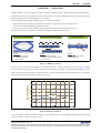
GDDR5 SGRAM is the latest generation of Elpida's high speed DRAM products. GDDR5 combines unprecedented memory
bandwidth with low system implementation costs and thus makes it the ideal DRAM platform for many applications including
graphic cards, game consoles and high performance computing.
For achieving ultra high bandwidth, GDDR5 introduces a variety of features that
• optimize the data eye by adapting I/O impedance and reference voltage to the actual system characteristics,
• allow efficient adaptation and tracking of interface timings,
• improve data integrity by adding hardware support for the detection and correction of transmission errors.
This document discusses these features and outlines the benefits for GDDR5-based applications.
'$7$(<(237,0,=$7,21
$'$37,9(,17(5)$&(7,0,1*
'$7$,17(*5,7<
' ' ' ' ' ' ' '
ǻW
' ' ' ' ' ' ' '
%HQHILWV
+LJKHVWVLJQDOTXDOLW\
+LJKHVWSHUIRUPDQFH
/RZ3&%FRVW
%HQHILWV
6WDEOHV\VWHPRSHUDWLRQ
1RQHHGIRUWUDFHOHQJWKPDWFKLQJ
/RZ3&%FRVW
%HQHILWV
+LJKHVWV\VWHPVWDELOLW\
(UURUWROHUDQFH
Figure 1: GDDR5 Key Concepts
The most obvious achievement with GDDR5 is the enormous increase in memory bandwidth as shown in Figure 2: GDDR5
provides more than twice the memory bandwidth compared to its predecessor, GDDR3. This extreme throughput enables users to
either reach new levels of performance for their applications or support an equivalent level of performance with e.g. only half the
interface width, resulting in a significant power and cost saving.
'DWDUDWHSHU3LQ>*ESV@
*''5
*''5
''5
Figure 2: Data Rate Comparison
To give an example: operated at a data rate of 5Gbps per pin or 20GB/s per device, a single GDDR5 SGRAM can read or write the
contents of 4 DVDs (4.7GB) in less than a second.
User’s Manual E1600E10 (Ver. 1.0)
5
Descriptions in this document are provided only for illustrative purpose in semiconductor product operation and application examples.
Use of this information is under the full responsibility of the customer. For details about the functions of individual products, refer to the
corresponding data sheet.
CHAPTER 1
OVERVIEW
When first introduced to the market, GDDR5-based graphic cards operated at data rates of about 3.6Gbps, while 5.0Gbps are
achieved today. Elpida is working closely with all major enablers to raise the data rate to 7Gbps and beyond in the near future.
DDR3 has been added to this bandwidth comparison as it is the latest DRAM generation originally defined for PC and server
applications, but also being adopted for graphic card applications.
User’s Manual E1600E10 (Ver. 1.0)
6
Descriptions in this document are provided only for illustrative purpose in semiconductor product operation and application examples.
Use of this information is under the full responsibility of the customer. For details about the functions of individual products, refer to the
corresponding data sheet.
CHAPTER 2
CHAPTER 2
FEATURES
FEATURES
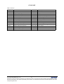
Table 1 compares the main features of DDR3 DRAM, GDDR3 SGRAM and GDDR5 SGRAM.
Table 1: Main Features of DDR3, GDDR3 and GDDR5
Item
DDR3 DRAM
GDDR3 SGRAM
GDDR5 SGRAM
Main densities
1Gbit, 2Gbit
1Gbit
1Gbit, 2Gbit
VDD, VDDQ
1.5V ±5%, (1.35V ±5%)
1.8V ±5%
1.5V ±3%, 1.35V ±3%
I/O Width
(4,) 8, 16
32
32 / 16
No. of banks
8
16
16
Prefetch
8
4
8
Burst length
4 (burst chop), 8
4 and 8
8
Access granularity
(32,) 64 / 128 bit
128 bit
256 bit
CRC
N/A
N/A
yes
Interface
SSTL
POD18
POD15, POD135
Termination
mid-level (VDDQ/2)
high-level (VDDQ)
high-level (VDDQ)
Package
BGA-78/96
BGA-136
BGA-170
GDDR5 Interface
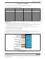
The GDDR5 SGRAM’s interface to the controller comprises 62 signals (see Figure 3):
• A 32-bit wide data bus (DQ), logically split into 4 bytes; each byte is accompanied by two additional signals /DBI (Data Bus
Inversion) and EDC (Error Detection and Correction) which are explained later in this document.
• Two differential forwarded data clocks for bytes 0 and 1 (WCK01, /WCK01) and bytes 2 and 3 (WCK23, /WCK23).
• Ten multiplexed address inputs (BA3-BA0, A12-A0, /ABI).
• Six command inputs (/RAS, /CAS, /WE, /CS, /CKE, /RESET).
• A differential clock (CK, /CK) for commands and addresses.
The other pins MF (Mirror Function), SEN (Scan Enable), VREFC (CMD/ADDR input reference), VREFD (data input reference)
and ZQ (impedance reference) are either pulled high or low or connected to external sources.
'4'4'%,('&
%\WH
:&.:&.
'DWD&ORFN%\WHV
'4'4'%,('&
%\WH
%$%$$$$%,
0X[¶HG$GGUHVV
&.&.
&RPPDQG&ORFN
5$6&$6:(&6
&.(5(6(7
&RPPDQG
'4'4'%,('&
%\WH
:&.:&.
'DWD&ORFN%\WHV
'4'4'%,('&
%\WH
1RWHV
('&SLQVDUHRXWSXWRQO\
$SLQIRU*ELWRQO\
3LQVQRWVKRZQ0)6(195()&95()'=4
Ä[[[³LQGLFDWHVDFWLYHORZVLJQDO
Figure 3: GDDR5 Interface
User’s Manual E1600E10 (Ver. 1.0)
7
Descriptions in this document are provided only for illustrative purpose in semiconductor product operation and application examples.
Use of this information is under the full responsibility of the customer. For details about the functions of individual products, refer to the
corresponding data sheet.
CHAPTER 2
FEATURES
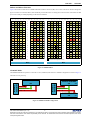
Ballout and Mirror Function
Figure 4 shows the two ballouts of a GDDR5 SGRAM with Mirror Function (MF) set to 0 and 1. The mirror function changes the
physical location of command, address, data and WCK pins and thus assists in routing devices back to back on the PCB. The MF
pin is tied to VSSQ or VDDQ depending on the desired orientation.
9664
'4
9664
'4
1&
$
95()'
'4
9664
'4
9664
9664
'4
9664
'4
1&
$
9664
'4
9664
9''4
'4
9''4
'4
966
%
966
'4
9''4
'4
9''4
9''4
'4
9''4
'4
966
%
966
'4
9''4
'4
9''4
9664
('&
9664
9664
9''
&
9''
9664
9664
('&
9664
9664
('&
9664
9664
9''
&
9''
9664
9664
('&
9664
9''4
'%,
9''4 :&. :&.
'
966
9''
9''4
'%,
9''4
9''4
'%,
9''4 :&. :&.
'
966
9''
9''4
'%,
9''4
9664
'4
9664
'4
9''4
(
9''4
'4
9664
'4
9664
9664
'4
9664
'4
9''4
(
9''4
'4
9664
'4
9664
9''4
'4
9''4
'4
9664
)
9664
'4
9''4
'4
9''4
9''4
'4
9''4
'4
9664
)
9664
'4
9''4
'4
9''4
95()' '4
9''
9''4
5$6
9''
966
*
966
9''
&6
9''4
9''
9''
9''4
&$6
9''
966
*
966
9''
:(
9''4
9''
966
9664
9''4
$
$
$
$
+
%$
$
%$
$
9''4
9664
966
966
9664
9''4
$
$
$
$
+
%$
$
%$
$
9''4
9664
966
5(6(7 &.(
$%,
$
5)8
-
6(1
&.
&.
=4
95()&
0)
$%,
$
5)8
-
6(1
&.
&.
=4
95()&
$
$
.
%$
$
%$
$
9''4
9664
966
966
9664
9''4
$
$
$
$
.
%$
$
%$
$
9''4
9664
966
0)
5(6(7 &.(
966
9664
9''4
$
$
9''
9''4
&$6
9''
966
/
966
9''
:(
9''4
9''
9''
9''4
5$6
9''
966
/
966
9''
&6
9''4
9''
9''4
'4
9''4
'4
9664
0
9664
'4
9''4
'4
9''4
9''4
'4
9''4
'4
9664
0
9664
'4
9''4
'4
9''4
9''4
1
9''4
1
9664
'4
9664
9''4
'4
9664
'4
9664
9664
'4
9664
9''4
'4
9664
'4
9664
9''4
'%,
9''4 :&. :&.
'4
3
966
9''
9''4
'%,
9''4
9''4
'%,
9''4 :&. :&.
3
966
9''
9''4
'%,
9''4
9664
('&
9664
9664
9''
5
9''
9664
9664
('&
9664
9664
('&
9664
9664
9''
5
9''
9664
9664
('&
9664
9''4
'4
9''4
'4
966
7
966
'4
9''4
'4
9''4
9''4
'4
9''4
'4
966
7
966
'4
9''4
'4
9''4
9664
'4
9664
'4
1&
8
95()' '4
9664
'4
9664
9664
'4
9664
'4
1&
8
95()'
'4
9664
'4
9664
'4
SLQLV2))ZKHQFRQILJXUHGWR[PRGH
SLQLV2))ZKHQFRQILJXUHGWR[PRGH
0) 0) Figure 4: GDDR5 Ballout
Clamshell Mode
The GDDR5 SGRAM can operate in a x32 mode or a x16 (clamshell) mode to allow a clamshell configuration as shown in Figure 5.
'4
*''56*5$0
*''56*5$0
[
[
0HPRU\
&RQWUROOHU
0HPRU\
&RQWUROOHU
The mode is set at power-up.
$GGUHVV&RPPDQG
'4
'4
0) $GGUHVV&RPPDQG
'4
*''56*5$0
[
0) Figure 5: GDDR5 Clamshell Configuration
User’s Manual E1600E10 (Ver. 1.0)
8
Descriptions in this document are provided only for illustrative purpose in semiconductor product operation and application examples.
Use of this information is under the full responsibility of the customer. For details about the functions of individual products, refer to the
corresponding data sheet.
CHAPTER 2
FEATURES
The benefit of clamshell mode is that users are able to quickly react on changing market conditions by easily creating new product
variations. E.g., by taking the same component from the inventory, utilizing the same controller, PCB layout and memory channel
width, the user can decide on the actual framebuffer size at a very late stage of the manufacturing process by
• either populating only one side of the PCB and configuring the GDDR5 to x32 mode, which results e.g. in a 1GB framebuffer
by using 8 pieces of 1Gbit with a 256-bit wide memory interface at the controller;
• or populating both sides of the PCB and configuring the GDDR5 to x16 mode, which results e.g. in a 2GB framebuffer by using
16 pieces of 1Gbit with a 256-bit wide memory interface at the controller.
Clamshell mode has no performance penalty because it preserves the point-to-point connection on the high-speed data bus. The
shared address and command interface can easily be connected by vias in the PCB and the use of mirror function mode which lets
these pins appear at the exact opposite locations.
Memory Organization
GDDR5 like DDR3 uses an 8n prefetch architecture to achieve high-speed operation. 8n prefetch architecture means that the
internal data bus to/from the memory core is 8 times as wide as the I/O interface but operated at only 1/8 of the I/O data rate. The
8n prefetch was chosen for GDDR5 as it offers the best compromise between the application’s need for fine access granularity and
fastest array speeds by using most advanced DRAM processes.
Elpida today offers 1Gbit and 2Gbit GDDR5 SGRAMs. The addressing of both densities can be depicted from Table 2: 1Gbit and
2Gbit differs only in the number of row address bits, while x32 mode and x16 mode differ only in the number of column address
bits. The number of banks and page size are the same for all configurations.
Table 2: Addressing Scheme
1Gbit
x32 mode
2Gbit
x16 mode
x32 mode
x16 mode
Memory Organization
32M x32
64M x16
64M x32
128M x16
Row Address
A0-A11
A0-A11
A0-A12
A0-A12
Column addresses
A0-A5
A0-A6
A0-A5
A0-A6
Bank address
BA0-BA3
BA0-BA3
BA0-BA3
BA0-BA3
Bank Groups
4
4
4
4
Page size
2 KB
2 KB
2 KB
2 KB
Clocking and Data Rates
The GDDR5 SGRAM runs off two different clocks as shown in Figure 6:
• Commands and addresses are referenced to the differential clock (CK, /CK); commands are registered at every rising edge of
CK; addresses are registered at every rising edge of CK and every rising edge of /CK.
• Read and write data are referenced to both edges of a free-running differential forwarded clock (WCK, /WCK) which replaces
the pulsed strobes (WDQS, RDQS) used in previous DRAMs such as GDDR3 or DDR3.
7
7
7
&.&.
&RPPDQG
$GGUHVV
*+]
5':5
%$
$&735(
&$
%$5$
5':5
*ESV
%$
*ESV
5$
*+]
:&.:&.
'DWD
([DPSOH)UHTXHQFLHVDQG'DWD5DWHV
*ESV
5' 5HDG
:5 :ULWH
$&7 $FWLYDWH
35( 3UHFKDUJH
%$ %DQN$GGUHVV
5$ 5RZ$GGUHVV
&$ &ROXPQ$GGUHVV
Figure 6: Relationship of Clock Frequencies and Data Rates
User’s Manual E1600E10 (Ver. 1.0)
9
Descriptions in this document are provided only for illustrative purpose in semiconductor product operation and application examples.
Use of this information is under the full responsibility of the customer. For details about the functions of individual products, refer to the
corresponding data sheet.
CHAPTER 2
FEATURES
It has been observed that clock frequency and data rate are sometimes mixed up when referring to the performance of a graphic
card. The specialty of GDDR5 is the 4X relationship between data rate and the CK clock, compared to the 2X relationship in DDR3
and GDDR3. In other words: a 4Gbps GDDR5 and a 2Gbps GDDR3 are both clocked at 1GHz. The GDDR5 clocking concept is
completed by the WCK data clock of 2X the command clock frequency.
Considering the CK and WCK frequency relationship as in Figure 6 and the burst length of 8, each Read or Write burst takes two
CK clock cycles. For gapless Read or Write operations READ and WRITE commands would be issued every second cycle like at
T0 and T2 in Figure 6. The intermediate command slot at T1 may be used to open (ACTIVATE) or close (PRECHARGE) a page
in one of the other banks in parallel with the ongoing Read or Write operation.
User’s Manual E1600E10 (Ver. 1.0)
10
Descriptions in this document are provided only for illustrative purpose in semiconductor product operation and application examples.
Use of this information is under the full responsibility of the customer. For details about the functions of individual products, refer to the
corresponding data sheet.
CHAPTER 3
CHAPTER 3
DATA EYE OPTIMIZATION
DATA EYE OPTIMIZATION
The performance limits when tweaking graphic cards are usually determined by crosstalk, inter-symbol interference (ISI) and all
sources of jitter in the interface between memory controller and DRAM, but not the DRAM itself.
The GDDR5 SGRAM provides a variety of features that all contribute to the dramatic improvement in data eye opening and system
stability for both Reads and Writes. Some of the features target the on-chip high-speed clocking scheme associated with the WCK
clocks, while other are dedicated to the actual signaling on the external interface or the interconnect between memory controller and
DRAM.
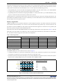
ODIC Architecture
The GDDR5 SGRAM chip architecture (see Figure 7) is called “ODIC” which stands for “outer DQ, inner control”; the architecture
is reflected by the ballout:
• The 32-bit data interface is physically split into 4 bytes, with one byte located in each corner of the package; bytes 0 and 1 share
a dedicated WCK clock and VREFD inputs; also bytes 2 and 3 share a dedicated WCK clock and VREFD inputs; both sections
are physically separated, with no data lines crossing the chip center.
• Address and command along with VREFC, the CK clock and other control signals are located in the center.
%$1.
%$1.
%$1.
%$1.
%$1.
%$1.
%$1.
%$1.
%$1.
%$1.
%$1.
%$1.
%$1.
%$1.
%$1.
%$1.
%<7(
&200$1'$''5(66
%<7(
5;7;
5;7;
&(175$/
&21752/
:&.
:&.
5;7;
5;7;
%<7(
&200$1'$''5(66
%<7(
%$1.
%$1.
%$1.
%$1.
%$1.
%$1.
%$1.
%$1.
%$1.
%$1.
%$1.
%$1.
%$1.
%$1.
%$1.
%$1.
Figure 7: GDDR5 SGRAM ODIC Architecture
The advantage of this architecture is that the internal WCK clock trees and high-speed data lines (shown in dark blue between the
RX/TX blocks and the pads) can be kept very short. The WCK clocks are also separated from the CK command clock which controls
User’s Manual E1600E10 (Ver. 1.0)
11
Descriptions in this document are provided only for illustrative purpose in semiconductor product operation and application examples.
Use of this information is under the full responsibility of the customer. For details about the functions of individual products, refer to the
corresponding data sheet.
CHAPTER 3
DATA EYE OPTIMIZATION
e.g. all internal memory array operations. Both contribute to an extremely low on-chip jitter and good supply noise immunity of the
GDDR5 SGRAM.
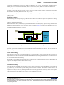
Write Data Latching and Clock Distribution
DDR3 and GDDR3 latch the Write data using a Write Data Strobe (WDQS). There is one data strobe per byte, and the strobe is
transmitted by the controller center-aligned with the Write data to provide equal setup and hold times at the DRAM’s receiver. The
DRAM must carefully maintain this phase relationship although the WDQS inside the DRAM has a fanout of 9 (8 DQ + DM) while
DQ and DM have a fanout of 1. This inherent mismatch has to be carefully compensated on-chip. This scheme has proven to be
working at the data rates of DDR3 and GDDR3, but was considered inadequate for the data rates of GDDR5.
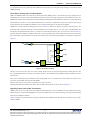
GDDR5 uses a scheme with direct latching data receivers (see Figure 8): 4 latches are directly connected to each DQ receiver. The
WCK data clock is internally divided by 2 and then distributed as a four-phase clock (0°, 90°, 180°, 270°) to the DQ latches. The
four phases correspond to the 4 data words (U.I.) which are received within two WCK cycles or one CK cycle as shown in Figure 6.
The main difference to DDR3 or GDDR3 is that there is no delay adjustment logic between DQ receiver and latch, and no fixed
phase relationship is specified between the WCK clock and data. The procedure for aligning WCK clock and data is explained in
Chapter 4.
'4
'
:&.
:&.
'
'
'
3//
4
'
4
4
'
4
4
'
4
4
'
4
Figure 8: Write Data Latching
The PLL cancels out any duty cycle error of the incoming WCK clock. It also suppresses high frequency WCK jitter above the
PLL’s bandwidth but tracks low frequency clock phase variations. The bandwidth is programmable and thus adjustable to system
characteristics.
The low jitter resulting from the combination of direct latching data receivers, short WCK clock trees and PLL have proven to be
key for the very high data rates achieved with GDDR5.
The PLL offers a bypass option which is targeted at lower speed operation.
The high-speed data path for Reads runs off the same four-phase internal WCK clocks (not shown in Figure 8).
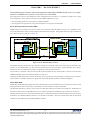
Signaling Scheme and On-Die Termination
GDDR5 carries the proven single-ended and VDDQ terminated signaling concept of GDDR3 to achieve highest data rates. By
maintaining these concepts within GDDR5 the rich experience gathered by users in system tweaking is allowing a fast and smooth
transition from GDDR3 to GDDR5.
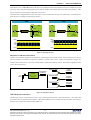
Figure 9 compares the Pseudo Open Drain (POD) signaling scheme of GDDR5 with the Stub Series Terminated Logic (SSTL)
scheme of DDR3.
User’s Manual E1600E10 (Ver. 1.0)
12
Descriptions in this document are provided only for illustrative purpose in semiconductor product operation and application examples.
Use of this information is under the full responsibility of the customer. For details about the functions of individual products, refer to the
corresponding data sheet.
CHAPTER 3
DATA EYE OPTIMIZATION
The POD driver uses a 40Ω/60Ω impedance that drives into a 60Ω equivalent on-die terminator (ODT) tied to VDDQ. Due to high
speed only single loads (P2P) being supported for the data bus. Address and command may also be dual loaded (P22P) e.g. when
used in conjunction with a clamshell configuration (see Figure 5).
The benefit of the VDDQ termination is that static power is only consumed when driving a Low which helps a system designer to
reduce the power consumption of the memory interface.
667/
32'
9''4
7;
5;
9''4
7;
î577
5;
577
=
=
î577
95()
î9''4
95()
î9''4
9''4
9''4
9,+
95()
9,/
9,+
95()
9,/
9664
9664
Figure 9: Signaling Schemes
Impedance Calibration and Offsets
The driver and terminator impedances are automatically calibrated against an external precision resistor connected to the ZQ pin.
This auto-calibration continuously compensates impedance variations from process, voltage and temperature changes. The
calibrated driver and terminator values may be further offset to optimize the matching of driver and terminator impedances to the
actual system characteristics.
2IIVHW38'ULYHU
=4
2KPV
$XWRFDOLEUDWHG
$XWR&DOLEUDWLRQ ,PSHGDQFH
(QJLQH
3URFHVV9ROWDJH
7HPSHUDWXUH
2IIVHW3''ULYHU
9664
2IIVHW7HUPLQDWLRQ
3XOOXS
,PSHGDQFH
3XOOGRZQ
,PSHGDQFH
7HUPLQDWLRQ
,PSHGDQFH
Figure 10: Impedance Offsets
VREFD Options and Offsets
The data input reference voltage VREF in Figure 9 may be either supplied externally or generated internally. A more stable data
eye has been observed using the internal VREF. A VREF offset capability allows to vertically shift the write data eye when the eye
opening is not symmetrical around the default VREF level.
User’s Manual E1600E10 (Ver. 1.0)
13
Descriptions in this document are provided only for illustrative purpose in semiconductor product operation and application examples.
Use of this information is under the full responsibility of the customer. For details about the functions of individual products, refer to the
corresponding data sheet.
CHAPTER 3
DATA EYE OPTIMIZATION
Data Bus Inversion (DBI), Address Bus Inversion (ABI)
Data Bus Inversion (DBI, see Figure 11) is a feature that reduces the supply noise induced jitter on the high-speed interface: it limits
the number of DQ lines per byte driving a Low to 4. DBI is used for Reads and Writes and operates as following: the transmitter
(the controller for Writes, the GDDR5 SGRAM for Reads) counts the number of zeros within a byte and decides whether to invert
(“0” count >4) or not invert (“0” count ≤ 4) the data conveyed on the DQs. The inversion is indicated on the additional signal /DBI
which can be considered a 9th data bit. The receiver (the GDDR5 SGRAM for Writes, the controller for Reads) performs the reverse
operation based on the level on the /DBI pin.
6LJQDOV
'4
'4
'4
'4
'4
'4
'4
'4
'%,
'DWD%XV
7UDQVPLWWHG'DWD
'%,
(QFRGH
5HFHLYHG'DWD
'%,
'HFRGH
Figure 11: Data Bus Inversion
The same function is also available for the address bus (Address Bus Inversion, ABI) and supported by the additional signal /ABI.
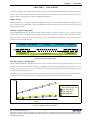
Unmatched Trace Length Routing
The DDR3 and GDDR3 data interfaces require low skew among the data lines and their associated data strobe in order to meet the
tight setup and hold timings constraints. Especially with higher data rates it is often a challenge to meet these timings, taking into
account some unavoidable skew in the system due to transistor process variation, package, power supply asymmetries or board
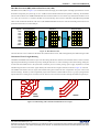
manufacturing tolerances. This leads to typical PCB layouts where the trace length is matched, as shown in Figure 12 on the left.
The GDDR5 data interface does not require such matched routing but considers the skew compensation one piece of the overall
interface trainings. The data eye will be significantly improved because the available PCB area allows e.g. larger spacing between
adjacent data lines, resulting in less cross talk. This also leads to even lower PCB cost when reducing the number of signal layers.
''5
*''5
*''5
Figure 12: PCB Routing with Unmatched and Matched Trace Length
User’s Manual E1600E10 (Ver. 1.0)
14
Descriptions in this document are provided only for illustrative purpose in semiconductor product operation and application examples.
Use of this information is under the full responsibility of the customer. For details about the functions of individual products, refer to the
corresponding data sheet.
CHAPTER 4
CHAPTER 4
ADAPTIVE INTERFACE TRAINING
ADAPTIVE INTERFACE TRAINING
The GDDR5 SGRAM provides hardware support for adaptive interface training. These trainings ensure that the GDDR5 SGRAM
is operated with the widest timing margins on all signals. They compensate for all imbalances in the interface timing resulting from
impedance mismatches, unmatched trace length in PCB routing and differences in path delays due to process, voltage and
temperature.
All interface trainings are fully orchestrated by the memory controller. The GDDR5 SGRAM assists the memory controller by
offering several unique hardware features that allow a fast and accurate training. It should be pointed out that all timing adjustments
are done at the memory controller only.
The duration of all trainings depends a lot on the specific implementation, data topology and algorithms, but in general has no
performance impact. In part this is achieved by certain hardware features inside the GDDR5 SGRAM that allow all trainings to
occur without accessing the (slower) memory core.
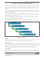
The generic interface training sequence can be depicted from Figure 13. The sophisticated sequence of interface trainings allows to
perform all training steps at the application’s maximum frequency.
The full training is performed at power-up or when certain operating conditions like clock frequency, PLL on/off or supply voltage
have changed on-the-fly during normal operation.
3RZHU8S
GHILQH[[PRGHDQGPLUURUIXQFWLRQ
$GGUHVV7UDLQLQJ
RSWLPL]HDGGUHVVLQSXWGDWDH\H
&ORFN7UDLQLQJ
VHDUFKIRULGHDO:&.WR&.FORFNDOLJQPHQW
5HDG'DWD7UDLQLQJ
VHDUFKIRUEHVWUHDGGDWDH\H
:ULWH'DWD7UDLQLQJ
VHDUFKIRUEHVWZULWHGDWDH\H
Figure 13: Interface Trainings
Power-Up
The device configuration (x32/x16 mode) and mirror function are detected at power-up. In addition, the ODT for the
address/command lines is set for normal or clamshell mode depending on the logic level on the /CKE pin.
Address Training
Once a stable CK clock is provided, commands may be issued to the GDDR5 SGRAM. The address training is optional and may
be used to center the address input data eye. The GDDR5 SGRAM supports address training by an internal signal bridge from its
address inputs to the DQ outputs. This bridge allows the controller to directly observe and adjust the address input timing.
Once the address input timing is trained, the controller may program the GDDR5 SGRAM’s configuration registers.
Clock Training
CK and WCK clocks require a certain phase relationship which may vary from device to device or after a configuration change such
as PLL-on /-off. This phase relationship ensures a reliable phase-over of write data from the (external) WCK clock domain to the
User’s Manual E1600E10 (Ver. 1.0)
15
Descriptions in this document are provided only for illustrative purpose in semiconductor product operation and application examples.
Use of this information is under the full responsibility of the customer. For details about the functions of individual products, refer to the
corresponding data sheet.
CHAPTER 4
ADAPTIVE INTERFACE TRAINING
(internal) CK clock domain for a correct write operation to the memory array. Likewise, the same phase relationship ensures a
reliable phase-over of read data from the (internal) CK clock domain to the (external) WCK clock domain and output drivers.
Clock training is initiated by the controller. The controller sweeps the WCK clocks against the CK clock, and the GDDR5 SGRAM
responds by a static signal indicating an “early” or “late” phase. The procedure continues until the optimum phase relationship is
detected which is indicated by the transition from “early” to “late”.
In most applications the phase relationship trained at power-up provides sufficient margin to cover any drift occurring during further
system operation.
Read Data Training
Read data training is the first step in aligning the data bus to the WCK clock. It includes two aspects: the alignment of the latching
clock in the memory controller to the center of the read data bit (bit training), and the detection of burst boundaries out of a
continuous read data stream (framing).
Read and Write Data Training can effectively be performed without the use of the memory array. Specific training commands utilize
the DRAM’s Read FIFO that usually acts as a temporary storage for read data. Figure 14 shows the regular data paths in green color,
and additional paths for data training in red color.
$GGUHVV
,QSXWV
0HPRU\
&RUH
5HDG
),)2
'DWD%XV
Figure 14: Data Paths for Read and Write Data Training
Initially the FIFO is pre-loaded with data being safely transmitted over the previously trained address bus. Once the FIFO has been
pre-loaded, special READ commands are issued repeatedly which return the FIFO data to the controller. The controller will then
sweeps its clock phase until the data are sampled correctly.
Write Data Training
Write data training is the final step in aligning the data bus to the respective WCK clock. It includes the same two aspects: the
alignment of the write data bits to the WCK clock at the DRAM’s data latch (bit training), and the detection of burst boundaries out
of a continuous write data stream (framing).
Knowing that the read path has been trained before, the controller iteratively writes and reads data to and from the Read FIFO and
sweeps the write data phase until the data are written correctly.
After Write Data Training all data eyes are expected to be well centered and the GDDR5 SGRAM is ready for normal operation.
Continuous Tracking
At the high data rates of GDDR5 even small changes in supply voltage or temperature will gradually shift the write and read data
eye position away from the trained optimum, making transmission errors more likely. The controller is able to observe and
compensate such data eye drift e.g. by monitoring the EDC pin which can be programmed to continuously send a clock-like pattern
(“EDC hold pattern”) to the controller. This is known as Clock and Data Recovery (CDR).
User’s Manual E1600E10 (Ver. 1.0)
16
Descriptions in this document are provided only for illustrative purpose in semiconductor product operation and application examples.
Use of this information is under the full responsibility of the customer. For details about the functions of individual products, refer to the
corresponding data sheet.
CHAPTER 4
ADAPTIVE INTERFACE TRAINING
To re-center the data eye it is suggested to repeat Write and Read Data Training at regular intervals. GDDR5 even allows to perform
such training in parallel with an ongoing regular refresh operation, a period where the data bus is settled when using other DRAMs
(e.g. DDR3). Such a carefully implemented “training during refresh” has no performance penalty.
High-End and Low-Cost Systems
The amount and accuracy of training depends a lot on the targeted data rates and other system characteristics. A high-end graphic
card will require all training steps at highest possible accuracy to tweak the data rate to a maximum. This may include a per-bit
training on the data lines to cancel out even small differences in signal flight times among the data lines.
Low-cost systems on the other side may skip address training and perform per-byte training instead of per-bit training or use more
coarse timing steps. The small differences in signal flight times or small training inaccuracies are acceptable for the target data rate.
This usually allows a more cost- and power-optimized memory controller design.
User’s Manual E1600E10 (Ver. 1.0)
17
Descriptions in this document are provided only for illustrative purpose in semiconductor product operation and application examples.
Use of this information is under the full responsibility of the customer. For details about the functions of individual products, refer to the
corresponding data sheet.
CHAPTER 5
CHAPTER 5
DATA INTEGRITY
DATA INTEGRITY
The manifold hardware features and training algorithms supported by GDDR5 already ensure very reliable
operation of GDDR5 based systems at very low bit error rates (BER).
Some applications however require BER some orders of magnitude lower than those e.g. acceptable for graphics card or game
console applications. These requests are addressed by the GDDR5 SGRAM in two ways:
• Securing the high-speed I/O’s signal integrity by adding redundancy.
• Securing partial write operations by using a more safe path for conveying the write data mask.
Error Detection and Correction (EDC)
GDDR5 supports error detection and correction (EDC) on its bidirectional DQ and /DBI lines using a cyclic redundancy check
(CRC-8) algorithm that is widely accepted in high-speed communication networks. The algorithm detects all single and double bit
errors. The procedure is as follows (see Figure 15):
0HPRU\&RQWUROOHU
*''56*5$0
:ULWH'DWD
&5&
(QJLQH
:ULWH'DWD
'DWD%XV
5HDG'DWD
"
&5&
(QJLQH
0HPRU\
&RUH
5HDG'DWD
('&
Figure 15: Error Detection and Correction
The GDDR5 SGRAM calculates the CRC checksum on-the-fly for each Read or Write burst and returns the checksum to the
controller on the dedicated EDC pin. The controller performs the same CRC calculation; if both checksums don’t match a
transmission error is assumed and the controller is supposed to repeat the command in error.
The procedure is asymmetric in the sense that only the controller performs the CRC check and takes corrective actions while the
GDDR5 SGRAM executes each command regardless of a CRC error.
Ultimately, this EDC feature may be used as an indicator for a data eye drift over time and trigger a retraining. However, the more
safe procedure is to schedule retraining on a regular basis and consider the EDC capability as additional safeguard.
Write Data Mask
Traditionally all DRAMs support partial write where individual bytes may be excluded from the write operation by the use of data
masking. This partial write is equivalent to a read-modify-write but consumes less memory bandwidth.
The data mask information is usually conveyed on an extra data mask (DM) pin associated with each data byte. The drawback of
this scheme is that a bit error on the DM signal is not recoverable, meaning that a masked byte may erroneously be overwritten.
The EDC feature would not solve the issue because the failure would be detected by the controller after the actual write has been
performed by the GDDR5 SGRAM. Therefore it was decided to implement a more safe scheme which sends the data mask
information via the address bus along with the WRITE command.
User’s Manual E1600E10 (Ver. 1.0)
18
Descriptions in this document are provided only for illustrative purpose in semiconductor product operation and application examples.
Use of this information is under the full responsibility of the customer. For details about the functions of individual products, refer to the
corresponding data sheet.
CHAPTER 6
CHAPTER 6
LOW POWER
LOW POWER
The power consumption of a GDDR5 memory interface has been widely addressed during the definition of features and device
operation. For a realistic estimation of the potential power saving it is recommended to consider the power saving of the whole
memory interface comprising memory controller, DRAM and the interface.
Supply Voltage
GDDR5 operates from a 1.5V supply voltage while GDDR3 still requires 1.8V. Elpida’s GDDR5 SGRAMs also support operation
at 1.35V. Elpida expects that the supply voltage of a GDDR5 based system will gradually decrease down to 1.2V or even 1.0V with
further technology shrinks.
Dynamic Voltage Scaling (DVS)
Elpida’s GDDR5 SGRAMs allow to change the supply voltage between 1.5V and lower voltages (e.g. 1.2V) “on-the-fly” and thus
scale the system’s power consumption to the actual system workload. The voltage transition may occur when the DRAM is set into
self refresh mode, as shown in Figure 16. The duration of the voltage transition is determined by the voltage regulator’s
characteristics and on-board buffer caps.
+,*+63(('
6(/)5()5(6+
/2:63(('
6(/)5()5(6+
+,*+63(('
&.
9'' 9
9'' 9
HJ9'' 9
Figure 16: Dynamic Voltage Scaling
Dynamic Frequency Scaling (DFS)
Elpida’s GDDR5 SGRAMs are specified to operate over a large contiguous frequency range starting from a data rate as low as
200Mbps up to the maximum rated data rate. While e.g. 400Mbps may be sufficient for displaying static images like from a web
browser or e-mail client, a data rate of e.g. 1.5Gbps may be required for HD video playback, and the maximum data rate will be
utilized by high-end gaming applications.
The memory system’s power consumption depends a lot on the clock frequency as shown in Figure 17 for one GDDR5 SGRAM.
It is therefore a good practise to scale the clock frequency on-the-fly to the actually required memory bandwidth.
,''
,''
$&735(F\FOH
,''3 3UHFKDUJHSRZHUGRZQ
,''1 $FWLYHVWDQGE\
,''5 5($'EXUVW
,'': :5,7(EXUVW
*ESV
'DWD5DWH
Figure 17: Supply Current vs. Data Rate
User’s Manual E1600E10 (Ver. 1.0)
19
Descriptions in this document are provided only for illustrative purpose in semiconductor product operation and application examples.
Use of this information is under the full responsibility of the customer. For details about the functions of individual products, refer to the
corresponding data sheet.
CHAPTER 6
LOW POWER
For optimum power saving it is recommended to combine DVS with DFS: the users define a set of operating points (data rates) for
their system, and with DVS they will scale the supply voltage to the lowest supported voltage at the specified data rates. The
DRAM’s internal voltages may be adjusted by the use of special register bits such that maximum power saving is achieved.
On-Die Termination (ODT)
The signal lines are usually terminated by a 60Ω impedance. At lower data rates it might be possible to achieve a stable operation
by using a “weak” termination of 120Ω or completely disabling ODT. In both cases the memory interface’s power consumption is
reduced. The GDDR5 SGRAM allows to control the ODT strength independently for address/command and data.
Write Latency
Write latency is the delay between a WRITE command and the actual start of a write burst. When the latency is set to small values
(i.e. WL = 3), the input receivers remain enabled; when set to large values (i.e. WL = 6 or 7), the input receivers turn on for the
duration of a write burst only. The power saving with larger WL values stems from the fact that write bursts account only for a small
percentage of the overall memory transactions. The performance penalty of a higher write latency is negligible.
Power-Down and Self Refresh
Like all other DRAMs GDDR5 supports Power-Down and Self Refresh mode.
• Power-Down disables the input buffers and internal clock trees while the external CK and WCK clocks remain active mainly to
keep the DRAM’s PLL and internal synchronization logic in a locked state; power-down supports a fast exit to quickly react on
a new memory request;
• Self refresh is the ultimate power-down state where the GDDR5 SGRAM retains the stored information without external
interaction; exit from self refresh takes longer than from power-down because the CK and WCK clocks need to be resynchronized and the PLL must re-lock.
Other Power Saving Features
Elpida’s GDDR5 SGRAMs support a few more power saving features which may be activated at lower data rates; the individual
saving potential is less than what e.g. is achieved with DVS and DFS, but helps when power consumption is a big concern or
competitive advantage:
• The DRAM’s voltage generators may be adapted to react slower on successive commands.
• The input receiver’s speed may be reduced.
• The WCK clock may be disabled during power-down.
User’s Manual E1600E10 (Ver. 1.0)
20
Descriptions in this document are provided only for illustrative purpose in semiconductor product operation and application examples.
Use of this information is under the full responsibility of the customer. For details about the functions of individual products, refer to the
corresponding data sheet.
GLOSSARY
Table 3: Glossary
ABI
Address bus inversion
GB/s
Gigabytes per second
BER
Bit error rate
GDDR3/5
Graphic double data rate 3/5
BGA
Ball grid array package
IDD
Supply current
CDR
Clock and data recovery
ODT
On-die termination
CK, /CK
Clock (true, inverted)
Mbps
Mega (one million) bits per second
CRC
Cyclic redundancy check
P2P, P22P
point-to-(two-)point
DBI
Data bus inversion
PLL
Phase locked loop
DQ
Data input/output
POD
Pseudo open-drain
DDR3
Double data rate 3
RX/TX
Receiver/transmitter
DFS
Dynamic frequency scaling
SGRAM
Synchronous graphic random access memory
DM
Data mask
SSTL
Stub series terminated logic
DRAM
Dynamic random access memory
VDD, VDDQ Supply voltage
DVS
Dynamic voltage scaling
VSS, VSSQ
Gbps
Giga (one billion) bits per second
WCK, /WCK Write clock (true, inverted)
User’s Manual E1600E10 (Ver. 1.0)
Ground
21
Descriptions in this document are provided only for illustrative purpose in semiconductor product operation and application examples.
Use of this information is under the full responsibility of the customer. For details about the functions of individual products, refer to the
corresponding data sheet.
MEMO
User’s Manual E1600E10 (Ver. 1.0)
22
Descriptions in this document are provided only for illustrative purpose in semiconductor product operation and application examples.
Use of this information is under the full responsibility of the customer. For details about the functions of individual products, refer to the
corresponding data sheet.
The information in this document is current as March 2010. The information is subject to change without notice.
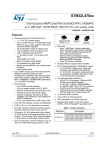
NOTES FOR CMOS DEVICES
1
PRECAUTION AGAINST ESD FOR MOS DEVICES
Exposing the MOS devices to a strong electric field can cause destruction of the gate
oxide and ultimately degrade the MOS devices operation. Steps must be taken to stop
generation of static electricity as much as possible, and quickly dissipate it, when once
it has occurred. Environmental control must be adequate. When it is dry, humidifier
should be used. It is recommended to avoid using insulators that easily build static
electricity. MOS devices must be stored and transported in an anti-static container,
static shielding bag or conductive material. All test and measurement tools including
work bench and floor should be grounded. The operator should be grounded using
wrist strap. MOS devices must not be touched with bare hands. Similar precautions
need to be taken for PW boards with semiconductor MOS devices on it.
2
HANDLING OF UNUSED INPUT PINS FOR CMOS DEVICES
No connection for CMOS devices input pins can be a cause of malfunction. If no
connection is provided to the input pins, it is possible that an internal input level may be
generated due to noise, etc., hence causing malfunction. CMOS devices behave
differently than Bipolar or NMOS devices. Input levels of CMOS devices must be fixed
high or low by using a pull-up or pull-down circuitry. Each unused pin should be connected
to VDD or GND with a resistor, if it is considered to have a possibility of being an output
pin. The unused pins must be handled in accordance with the related specifications.
3
STATUS BEFORE INITIALIZATION OF MOS DEVICES
Power-on does not necessarily define initial status of MOS devices. Production process
of MOS does not define the initial operation status of the device. Immediately after the
power source is turned ON, the MOS devices with reset function have not yet been
initialized. Hence, power-on does not guarantee output pin levels, I/O settings or
contents of registers. MOS devices are not initialized until the reset signal is received.
Reset operation must be executed immediately after power-on for MOS devices having
reset function.
CME0107
User’s Manual E1600E10 (Ver. 1.0)
23
Descriptions in this document are provided only for illustrative purpose in semiconductor product operation and application examples.
Use of this information is under the full responsibility of the customer. For details about the functions of individual products, refer to the
corresponding data sheet.
The information in this document is subject to change without notice. Before using this document, confirm that this is the latest version.
No part of this document may be copied or reproduced in any form or by any means without the prior
written consent of Elpida Memory, Inc.
Elpida Memory, Inc. does not assume any liability for infringement of any intellectual property rights
(including but not limited to patents, copyrights, and circuit layout licenses) of Elpida Memory, Inc. or
third parties by or arising from the use of the products or information listed in this document. No license,
express, implied or otherwise, is granted under any patents, copyrights or other intellectual property
rights of Elpida Memory, Inc. or others.
Descriptions of circuits, software and other related information in this document are provided for
illustrative purposes in semiconductor product operation and application examples. The incorporation of
these circuits, software and information in the design of the customer's equipment shall be done under
the full responsibility of the customer. Elpida Memory, Inc. assumes no responsibility for any losses
incurred by customers or third parties arising from the use of these circuits, software and information.
[Product applications]
Be aware that this product is for use in typical electronic equipment for general-purpose applications.
Elpida Memory, Inc. makes every attempt to ensure that its products are of high quality and reliability.
However, users are instructed to contact Elpida Memory's sales office before using the product in
aerospace, aeronautics, nuclear power, combustion control, transportation, traffic, safety equipment,
medical equipment for life support, or other such application in which especially high quality and
reliability is demanded or where its failure or malfunction may directly threaten human life or cause risk
of bodily injury.
[Product usage]
Design your application so that the product is used within the ranges and conditions guaranteed by
Elpida Memory, Inc., including the maximum ratings, operating supply voltage range, heat radiation
characteristics, installation conditions and other related characteristics. Elpida Memory, Inc. bears no
responsibility for failure or damage when the product is used beyond the guaranteed ranges and
conditions. Even within the guaranteed ranges and conditions, consider normally foreseeable failure
rates or failure modes in semiconductor devices and employ systemic measures such as fail-safes, so
that the equipment incorporating Elpida Memory, Inc. products does not cause bodily injury, fire or other
consequential damage due to the operation of the Elpida Memory, Inc. product.
[Usage environment]
Usage in environments with special characteristics as listed below was not considered in the design.
Accordingly, our company assumes no responsibility for loss of a customer or a third party when used in
environments with the special characteristics listed below.
Example:
1) Usage in liquids, including water, oils, chemicals and organic solvents.
2) Usage in exposure to direct sunlight or the outdoors, or in dusty places.
3) Usage involving exposure to significant amounts of corrosive gas, including sea air, CL 2 , H 2 S, NH 3 ,
SO 2 , and NO x .
4) Usage in environments with static electricity, or strong electromagnetic waves or radiation.
5) Usage in places where dew forms.
6) Usage in environments with mechanical vibration, impact, or stress.
7) Usage near heating elements, igniters, or flammable items.
If you export the products or technology described in this document that are controlled by the Foreign
Exchange and Foreign Trade Law of Japan, you must follow the necessary procedures in accordance
with the relevant laws and regulations of Japan. Also, if you export products/technology controlled by
U.S. export control regulations, or another country's export control laws or regulations, you must follow
the necessary procedures in accordance with such laws or regulations.
If these products/technology are sold, leased, or transferred to a third party, or a third party is granted
license to use these products, that third party must be made aware that they are responsible for
compliance with the relevant laws and regulations.
M01E0706
User’s Manual E1600E10 (Ver. 1.0)
24
Descriptions in this document are provided only for illustrative purpose in semiconductor product operation and application examples.
Use of this information is under the full responsibility of the customer. For details about the functions of individual products, refer to the
corresponding data sheet.