1
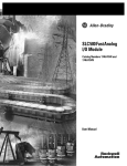
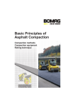
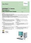
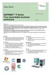
Hisp
SE + SC
Product Documentation
Split Air Conditioner for:
Cooling
Heating
Air Filtration
Indoor Ventilation
Freecooling with Outdoor Fresh Air
Emergency Cooling
English
code 272069 - rev. 13.10.2000
Issued by TDS
English
Hisp
INDEX
1 - The series . . . . . . . . . . . . . . . . . . . . . . . . . . . . . . . . . . . . . . . . . . . . . . . . . . . . . . . . . . . . . . . . . . . . 1
1.11.21.31.41.51.6-
Main features . . . . . . . . . . . . . . . . . . . . . . . . . . . . . . . . . . . . . . . . . . . . . . . . . . . . . . . . . . . . . . . . . . . . . . . . . . . .
Accessibility . . . . . . . . . . . . . . . . . . . . . . . . . . . . . . . . . . . . . . . . . . . . . . . . . . . . . . . . . . . . . . . . . . . . . . . . . . . . .
Installation . . . . . . . . . . . . . . . . . . . . . . . . . . . . . . . . . . . . . . . . . . . . . . . . . . . . . . . . . . . . . . . . . . . . . . . . . . . . . .
Metal cabinet . . . . . . . . . . . . . . . . . . . . . . . . . . . . . . . . . . . . . . . . . . . . . . . . . . . . . . . . . . . . . . . . . . . . . . . . . . . .
Refrigeration circuit . . . . . . . . . . . . . . . . . . . . . . . . . . . . . . . . . . . . . . . . . . . . . . . . . . . . . . . . . . . . . . . . . . . . . .
Evaporating section . . . . . . . . . . . . . . . . . . . . . . . . . . . . . . . . . . . . . . . . . . . . . . . . . . . . . . . . . . . . . . . . . . . . . .
1.6.1- Heat transfer coil . . . . . . . . . . . . . . . . . . . . . . . . . . . . . . . . . . . . . . . . . . . . . . . . . . . . . . . . . . . . . . . . .
1.6.2- Fan features . . . . . . . . . . . . . . . . . . . . . . . . . . . . . . . . . . . . . . . . . . . . . . . . . . . . . . . . . . . . . . . . . . . . .
1.7- Motor-condensing section . . . . . . . . . . . . . . . . . . . . . . . . . . . . . . . . . . . . . . . . . . . . . . . . . . . . . . . . . . . . . . .
1.7.1- Heat transfer coil . . . . . . . . . . . . . . . . . . . . . . . . . . . . . . . . . . . . . . . . . . . . . . . . . . . . . . . . . . . . . . . . .
1.7.2- Fan features (condensing temperature control with Variex, variable fan speed) . . . . . . . . . . .
1.8- Air filter section . . . . . . . . . . . . . . . . . . . . . . . . . . . . . . . . . . . . . . . . . . . . . . . . . . . . . . . . . . . . . . . . . . . . . . . . . .
1.9- Electric board . . . . . . . . . . . . . . . . . . . . . . . . . . . . . . . . . . . . . . . . . . . . . . . . . . . . . . . . . . . . . . . . . . . . . . . . . . .
1.10-Electronic control . . . . . . . . . . . . . . . . . . . . . . . . . . . . . . . . . . . . . . . . . . . . . . . . . . . . . . . . . . . . . . . . . . . . . . . .
1.10.1- Microface control . . . . . . . . . . . . . . . . . . . . . . . . . . . . . . . . . . . . . . . . . . . . . . . . . . . . . . . . . . . . . . . . .
1.10.2- Microface xontrol plus Hiromatic Grafic (optional) . . . . . . . . . . . . . . . . . . . . . . . . . . . . . . . . . . . . .
1.11-Freecooling (optional) . . . . . . . . . . . . . . . . . . . . . . . . . . . . . . . . . . . . . . . . . . . . . . . . . . . . . . . . . . . . . . . . . . . .
1.12-Electric heating (optional) . . . . . . . . . . . . . . . . . . . . . . . . . . . . . . . . . . . . . . . . . . . . . . . . . . . . . . . . . . . . . . . . .
1.13-Emergency cooling (optional) . . . . . . . . . . . . . . . . . . . . . . . . . . . . . . . . . . . . . . . . . . . . . . . . . . . . . . . . . . . . .
1.14-Noise level . . . . . . . . . . . . . . . . . . . . . . . . . . . . . . . . . . . . . . . . . . . . . . . . . . . . . . . . . . . . . . . . . . . . . . . . . . . . . .
1.15-Installation accessories . . . . . . . . . . . . . . . . . . . . . . . . . . . . . . . . . . . . . . . . . . . . . . . . . . . . . . . . . . . . . . . . . . .
1.16-Packing . . . . . . . . . . . . . . . . . . . . . . . . . . . . . . . . . . . . . . . . . . . . . . . . . . . . . . . . . . . . . . . . . . . . . . . . . . . . . . . . .
1.17-Tests and reference norms . . . . . . . . . . . . . . . . . . . . . . . . . . . . . . . . . . . . . . . . . . . . . . . . . . . . . . . . . . . . . . . .
1
1
1
2
2
2
2
4
4
4
4
4
4
5
5
5
6
6
6
7
8
8
8
2 - Technical data and performances . . . . . . . . . . . . . . . . . . . . . . . . . . . . . . . . . . . . . . . . . . . . . . . 9
2.1- Performances . . . . . . . . . . . . . . . . . . . . . . . . . . . . . . . . . . . . . . . . . . . . . . . . . . . . . . . . . . . . . . . . . . . . . . . . . .
2.2- Electric data . . . . . . . . . . . . . . . . . . . . . . . . . . . . . . . . . . . . . . . . . . . . . . . . . . . . . . . . . . . . . . . . . . . . . . . . . . . .
2.2.1- Standard features . . . . . . . . . . . . . . . . . . . . . . . . . . . . . . . . . . . . . . . . . . . . . . . . . . . . . . . . . . . . . . .
2.2.2- Optional features . . . . . . . . . . . . . . . . . . . . . . . . . . . . . . . . . . . . . . . . . . . . . . . . . . . . . . . . . . . . . . . .
2.2.3- Differential current protection switch and cable size, AC supply . . . . . . . . . . . . . . . . . . . . . . .
2.2.4- Main disconnector switch and cable size, DC supply . . . . . . . . . . . . . . . . . . . . . . . . . . . . . . . . .
2.3- Application ranges . . . . . . . . . . . . . . . . . . . . . . . . . . . . . . . . . . . . . . . . . . . . . . . . . . . . . . . . . . . . . . . . . . . . . .
12
27
27
28
28
28
29
Overall dimensions . . . . . . . . . . . . . . . . . . . . . . . . . . . . . . . . . . . . . . . . . . . . . . . . . . . . . . . . . . . . . . . .
Examples of installation . . . . . . . . . . . . . . . . . . . . . . . . . . . . . . . . . . . . . . . . . . . . . . . . . . . . . . . . . . .
Electrical connections . . . . . . . . . . . . . . . . . . . . . . . . . . . . . . . . . . . . . . . . . . . . . . . . . . . . . . . . . . . . .
Refrigeration connections . . . . . . . . . . . . . . . . . . . . . . . . . . . . . . . . . . . . . . . . . . . . . . . . . . . . . . . . .
30
36
39
39
English
Hisp
1 - The series
Subject
SE+SC04; SE+SC05; SE+SC06; SE+SC08: SE+SC10; SE+SC14
split air conditioners
direct expansion units with capillary (SE+SC04; SE+SC05; SE+SC06) or thermostatic valve
(SE+SC08; SE+SC10; SE+SC14)
microprocessor control
flexible installation
SE+SC05
5 kW model
Split Condensing unit (outdoor)
Split Evaporating unit (indoor)
1.1 -
Main features
Functions
Split units composed by an evaporating indoor unit for ceiling or wall installation and a motor-condensing
outdoor unit, mainly for electronic equipped shelters, process centres, telecommunications sites from 4
to 14 kW of nominal cooling capacity.
The system provides air filtration, indoor ventilation, cooling, heating, freecooling with outdoor fresh air
to assure the useful climate in the site. The unit can accept emergency power supply of 48 Vdc or 24 Vdc,
assuring indoor ventilation and freecooling.
1.2 -
Accessibility
Easy Servicing
In the evaporating unit the accessibility is granted from the bottom side; removing three screwed panels
and the air discharge grille, it's possible to operate the ordinary and the extraordinary maintenance of the
following components: air filter, coil, fan, electrical panel, heaters (opt.), freecooling module (opt.). In the
motor-condensing unit, a dedicated panel is covering the compressor, the cooling circuit and the electri
cal board; a frontal panel has to be used for the extraordinary maintenance of the axial fan. All the outdoor
fixing screws are anti-vandalism and weather-proof type (special rubber gasket as standard), requiring
a special tool to be removed (supplied with the unit).
1.3 -
Installation
Flexibility
Thanks to its special design, the evaporating unit is available for ceiling (standard factory configuration)
or wall installation (an easy setting, always possible on site, is needed) according to the specific needs.
With vertical installation, the air discharge is upflow.
1
English
1.4 -
Hisp
Metal cabinet
Compactness
Hisp frame consists of riveted steel panels, treated with powder coating colour as standard (RAL7035).
The motor-condensing unit is designed to be installed outdoor and resist to worst weather conditions.
The screws are hermetic (special rubber gasket as standard) and antivandalism (they can be removed
only with specific tools) and allow the opening from the front.
The evaporating unit SE has to be placed indoor, to supply the conditioned air inside the room or shelter:
it's available in basic version (without Freecooling option) with smaller footprint, and in Freecooling ver
sion, inclusive of the additional module for the fresh air modulating management. The air inlet is located
in the rear panel (basic version, without Freecooling option), and the air supply is done from the front sec
tion, through an integrated grille, complete with double row of orientable fins (horizontal and vertical set)
as standard.
The thermo-acoustic insulation of the panels is 10 mm thick, density 70 kg/m3 and of the type mineral
wool.
The motor-condensing unit SC takes the external air from the rear, to discharge it on the front section:
a frontal metal safety grid prevents contact with the fan, and a special design of the front panel avoids
damaging of the fan motor.
The compressor is located in the left side of the motor-condensing unit, separated from the air flow.
1.5 -
Refrigeration circuit
Efficiency
There is a single refrigeration circuit with a hermetic compressor (rotary on SC04, 05, 06 models; scroll
on SC08, 10, 14).
An internal thermal protection against overheating of the motor is provided as standard.
The circuit, for SE+SC04, SE+SC05 and SE+SC06, incorporates a capillary tube which controls the re
frigerant flow to the evaporator (SE unit); a filter dryer is provided in the liquid line to eliminate all moisture
for maximum efficiency and an increased working life.
On SE+SC08; SE+SC10 and SE+SC14 the circuit is equipped with thermostatic valve and sight glass.
The compressor is equipped with two pressure switches for protection against high condensing (HP) and
low evaporating (LP) pressures. The low pressure switch features automatic reset and a delay for winter
operation, whilst to avoid compressor cycling at high discharge pressures. The high pressure switch is
equipped with manual reset for safety reasons.
1.6 -
Evaporating section
Cooling capacity
1.6.1 - Heat transfer coil
This consists of a slab coil in copper tubes with aluminium waved fins and with a large face area so as
to increase the SHR (Sensible Heat Ratio) and optimise the EER (Energy Efficiency Ratio); this is achieved
by reducing the air pressure drop and turbulence and increasing the evaporating temperature, thus the
efficiency, of the compressor. A galvanized steel basin is provided for the drainage water: its special design
allows safe operations indifferently in horizontal or vertical position.
2
English
Hisp
Operation diagram:
SIDE VIEW
1
3
4
5
SIDE VIEW
9
6
11
8
10
2
7
Unit without freecooling
3
4
5
9
6
11
1
10
Unit with freecooling
inlet air return
conditioned air
freecooling air
13
FRONTAL VIEW
12
TOP VIEW
16
14
15
POS.
1
2
3
4
5
6
7
8
DESCRIPTION
Air return grille
Freecooling damper (Freecooling version only)
Air filter
Evaporator coil
Evaporator unit fan
Air discharge duct
Damper motor (Freecooling version only)
Air suction grille (Freecooling version only)
POS.
9
10
11
12
13
14
15
16
DESCRIPTION
Electric heaters (optional)
Heater safety thermostat (heating version only)
Electrical panel evaporating unit
Condenser fan
Electrical panel condensing unit
Refrigeration compressor
Variex
Condenser coil
3
English
Hisp
1.6.2 - Fan features
The standard SE units are equipped with two centrifugal fans with forwardly bladed impellers and housing
in deep galvanized steel plate. One electrical motor is directly coupled on the motor shaft, with internal
thermal protection. The impellers are statically and dynamically balanced with lifetime lubricated bearings
for quiet, vibration-free operation.
The motor is single-phase, IP44.
If the unit is complete with the Emergency Freecooling option, the evaporating fan section is composed
by two free wheel fans (backward curved blades), each of them direct driven by a dc electric motor.
1.7 -
Motor-condensing section
Reliability
1.7.1 - Heat transfer coil
A wide face air condensing coil is provided. It is designed in copper tubes with aluminium fins and sized
to allow operations up to 45 °C outdoor air temperature.
1.7.2 - Fan features (condensing temperature control with Variex, variable fan speed)
The units are equipped with 4-pole axial fan. The electrical motor is directly coupled on the motor shaft,
with internal thermal protection and IP44. The innovative design of the impeller allows the maximum effi
ciency with the minimum noise.
As standard, the condensing fan speed is smoothly regulated by Variex control, in order to maintain
constant the condensing pressure and therefore the temperature. Two kind of advantages: higher reliabil
ity for less start/stops of the compressor, and lower noise disturbance because the fan is running at a lower
speed, mainly during night time, and with less discontinuity.
1.8 -
Air filter section
Air Purity
The filter section is placed vertically, before the evaporating coil and provides filtration of the recirculated
or the fresh air to obtain the required degree of air cleanliness in the room. The filter can be removed from
the bottom of the unit (indoor side) by simply opening the relevant panel and unlocking the support brack
et. Hisp SE unit features 48 mm (SE 04-05-06), 60 mm (SE 08-10-14) thick, pleated type air filter, spe
cially designed to minimize the pressure drop and improve the efficiency. The standard filter class is EU3,
according to Eurovent EU4/5 standard).
1.9 -
Electric board
Power Supply with Safety
The electrical board of the indoor SE unit is housed in a compartment isolated from the air stream and
closed by a screwed dedicated panel. Power connections and auxiliary wires can be driven on right or
left side, through two couples of dedicated opening, to increase the flexibility during the installation.
The electrical board is built in accordance with IEC 204-1 recommendations.
The units are designed for the following power supply:
230
400
230
230
460
V
V
V
V
V
1 ph
3 ph
1 ph
3 ph
3 ph
50 Hz
50 Hz
60 Hz
60 Hz
60 Hz
(SE+SC
(SE+SC
(SE+SC
(SE+SC
(SE+SC
04-05-06)
08-10-14)
04-05-06)
08-10-14)
08-10-14)
One circuit breaker with magnetic and thermal protection against short circuits and current overload is
supplied for the electrical apparatus. A single phase transformer for power supply to the 24 V to the elec
tronic control and to a secondary circuit is provided for maximum safety. Automatic restart is provided after
a power failure.
The outdoor SC unit receives main power supply from the indoor unit, together with the control signals
collected in a dedicated weather-proof terminal block.
4
English
Hisp
1.10 - Electronic control
Cleverly Control
1.10.1 - Microface control
The standard microprocessor control is Microface.
Where. The Microface electronic board is located in the electrical panel (SE evaporating unit), connected
to a remote display installed in a metallic box and placed inside the room or the container.
Display. The interface with the user is a 3-digit backlighted display enabling the machine SET-UP in a
very simple way by a tree menu that, as an alternative to the parameter number (which can be easily found
in the user's manual), gives an abbreviation of the selected function.
Remote alarms. There is a warning contact with HT, LT and heater failure. There is another alarm contact
with LP, HP, fan failure, and control failure. With the Microface it is possible to have, as option, an additional
alarm board allowing further remote alarms.
Management of Freecooling. There is an intelligent management of the freecooling, starting not to a fixed
ambient temperature, but depending from the difference (Tset - Tout) compared with a settable value. At
the same time there is a control of the delivery air temperature, never allowed to go under a defined value.
Connectivity. The Microface has been produced and studied to obtain high performances concerning con
nectivity. Hirobus (the local area network of controllers) allows to connect up to 16 Microface (16 units)
controlling the group; this means sharing the adjustment parameters, rotating the units during their opera
tion keeping 1, 2 or 3 units in stand by and re-activating them when required.
Stand-by. It is sufficient to connect two units or more (up to 16) with a bus cable to create a local network:
in case of failure or overload of the running unit, the second one will start automatically.
Automatic rotation. With this control it is possible to obtain the unit rotation and also the working of the two
units at the same time if necessary.
Cascade. Two or more units can really work as a team: through the subdivision of the proportional band
from Microface, it is possible to split the heat load on the available Hisp air conditioners.
1.10.2 - Microface control plus Hiromatic Graphic (optional)
Microface is a Hi-Tech solution that enables the connection of the display for Hiromatic Graphic, for the
temperature record over the last 24 hours and the alarm report functionality The Microface (if connected
with Hiromatic Graphic) also records the number of working hours of the main components (fan, compres
sor, heating elements), controls the starts and stops of the compressor cleverly, shows the alarms avail
able in the unit, and allows the setting of the important parameters covered by 3 password levels.
Also with a serial port RS422, available as option in the Hiromatic Graphic, we can link together in a net
work by the Hirolink accessory the Hisp units located in different sites. So we can monitorize with a person
al computer all the installed air conditioners.
5
English
Hisp
1.11 - Freecooling (optional)
Energy Saving
All units can be made available with the freecooling option (FC). Please see the concept diagram.
In this way we save energy and achieve better reliability, for the lower number of compressor starts and
stops, and the shorter running time.
Inside the SE evaporating unit an internal damper modulates his position from 0 to 100% of fresh air, just
to achieve the required cooling capacity. The exhaust air is discharged outdoor through an overpressure
damper mounted on the wall and available as accessory.
The consensus to FC is given when the difference between the indoor and outdoor air temperatures is
higher than a set value. No freecooling and mechanical cooling are allowed at the same time.
Rear view:
Circular ducts version
Rectangular duct version
1.12 - Electric heating (optional)
Heating
The heating option is available with electric heaters, located in the air discharge plenum, for a total of 3
kW (SE 04-05-06) or 6 kW (SE 08-10-14) capacity. There is one stage, one contactor and ON-OFF
temperature control. Each heater is fitted with safety thermostat, with manual reset from the air discharge
grille.
1.13 - Emergency cooling (optional)
Ventilating Without Interruption
The unit is optionally equipped with an emergency cooling system that allows to supply the indoor fans,
the control and the motor damper, if fitted with 48 Vdc or 24 Vdc power supply. When it is required to
guarantee the air circulation inside the room or shelter even when the ac main electric supply is missing.
For this purpose, two free wheel fans (backward curved blades), each of them direct driven by a dc electric
motor, represent the evaporating fan section, allowing to use the 24 Vdc or 48 Vdc batteries that are gener
ally installed inside the shelter to provide emergency energy to the electronic equipment.
The emergency cooling consists of a system (evaporating fans, control and damper motor) always sup
plied by dc power (48V or 24V options are available); the remaining components are supplied by ac pow
erper motor) always supplied by dc power (48V or 24V options are available); the remaining components
are supplied by ac power (230V or 400V, according to the model of the unit). When the main supply fails,
the system takes energy from the dc batteries and the compressor is not powered. So, in this way, the
control is energized, the air recirculation inside the shelter is ensured and also the freecooling, if fitted,
is working.
6
English
Hisp
1.14 - Noise level
Silentness
Sound pressure levels, for measurement carried out with fan speed regulator (Variex).
Octave band frequency (Hz)
31.5
63
125
250
500
1000
2000
4000
8000
Sound pressure
level
[dB(A)]
58
52
56
50
48
51
49
46
42
55
48
55
61
58
56
54
52
51
49
60
SE 14
49
56
61
58
57
55
52
51
50
62
SC 04
55
57
54
46
44
40
37
28
23
46
55
58
53
49
44
40
37
28
23
47
55
55
55
50
47
41
38
28
24
48
46
52
57
56
54
50
47
46
45
56
SC 10
46
53
58
56
54
52
48
46
45
57
SC 14
53
57
60
58
57
53
49
47
45
59
Model
50Hz
SE 04
SE 05
SE 06
SE 08
SE 10
Indoor, free field at 2 m in front
Indoor
of the unit
SC 05
SC 06
SC 08
Outdoor, free field at 2 m in
front of the unit
Sound pressure levels, for measurement carried out with fan speed regulator (Variex).
Octave band frequency (Hz)
Model
60Hz
SE 04
SE 05
SE 06
SE 08
SE 10
Indoor, free field at 2 m in front
Indoor
of the unit
31.5
63
125
250
500
1000
2000
4000
8000
Sound pressure
level
[dB(A)]
48.5
53
57.5
57
53.5
49.5
47
44.5
42.5
56
60.5
60
61
56
54.5
56
54.5
52
49.5
61
SE 14
67.5
63
60.5
57.5
59
60
59
56
51.5
65
SC 04
39
43.5
47
51.5
46.5
43
39.5
36
31
49
SC 05
43
47.5
51
55
50
47.5
44
40
35.5
53
SC 06
45
49.5
53
57
52
49.5
46
42
37.5
55
52.5
57.5
62.5
57.5
54.5
50
49
44
39
57
SC 10
48.5
53.5
58
61
57
52
50.5
46
41
59
SC 14
49.5
54.5
59
64
61.5
57.5
53
48.5
45
63
SC 08
Outdoor, free field at 2 m in
front of the unit
7
English
Hisp
1.15 - Installation accessories
Finishing
The Freecooling unit can be supplied complete with all main accessories for the installation:
Wall indoor plate for Freecooling flexible duct connections (two circular holes);
Freecooling flexible ducts (ø202 mm for SE+SC04-05-06 models, ø250 mm for SE+SC08-10-14)
complete with professional fixing clamps;
Wall indoor plate for Freecooling rigid duct connection (single rectangular hole);
External rain-proof grille with metallic prefilter for Freecooling intake;
Overpressure gravity damper, to discharge outdoor the exhaust air from inside, especially designed
for this machine;
External rain-proof grille, to protect the overpressure damper from worst weather and foreign bodies;
All grilles and dampers are made of extruded aluminium, to achieve the maximum lifetime.
The motor-condensing unit can also be supplied complete with the wall mounting kit, made up of a cou
ple of shelves in galvanized steel, painted with polyester powders in the color RAL 9002 and smooth finish
ing, suitable vibration-damping supports in elastomer and all the small connecting parts in stainless
steel, with screw anchors for wall mounting (see Fig. Wall mounting).
NOTE: the screw anchors supplied in the kit are to be used only in case of shelf mounting on concrete
or brick walls (hollow bricks included). Do not use on sandwich walls (e.g. container) or with unknown
composition. In these cases the most suitable mounting system for the specific material shall be applied.
1.16 - Packing
Delivery
Standard packing consists of a wooden pallet and cardboard box. Polythene foam protects the units'
painted surfaces. On request, a cardboard box with an additional wooden crate or wooden case for sea
transport can be supplied.
1.17 - Tests and reference norms
Production System Quality
The units are planned, manufactured and tested in compliance to the European directives 98/37/CE
(89/392/CEE; 91/368/CEE; 93/68/CEE); 89/336/CEE; 73/23/CEE. More deeply, the unit is verified about
Electromagnetic Compactibility according to the following standards: EN55022, radiated and conducted
emission, class B; ENV 50/40/IEC 801-3 radiated immunity; IEC 801-6: radiated immunity on the supply/
signal cables; IEC 801-4 fast transient; IEC 801-2 ESD.
According to that, the machine is supplied complete with a test certificate and a certificate of conformity
to the European directives. Hisp units are marked ''CE".
Further, the Company Quality System of Air Conditioning Division is approved by Lloyd Register Quality
Assurance, in compliance with the standards UNI EN ISO 9001: 1994 and the product is the result of activi
ties carried out according to the provisions contained in the Quality procedures and plans.
8
English
Hisp
2 - Technical data and performances
HISP model
SE+SC04
POWER SUPPLY
SE+SC05
SE+SC06
SE+SC08
SE+SC10
230/1/50
SE+SC14
400/3/50
CABINET
Frame
galvanized steel
Painting
polyester powder
Insulation type
mineral wool, 10 mm thick
OVERALL DIMENSIONS (SE internal unit)
Height
mm
310
395
Width
mm
800
1100
Depth
mm
Weight
kg
800
(1050 included optional Freecooling)
54
Optional Freecooling module weight
= 8 kg
1095
(1395 included optional Freecooling)
110
110
120
Optional Freecooling module weight
= 12 kg
OVERALL DIMENSIONS (SC external unit)
Height
mm
537
690
Width
mm
800
1050
Depth
mm
Weight
kg
285
49
49
500
56
112
115
125
EVAPORATING COIL
Tubes material / Fins material
copper / aluminium
EVAPORATING SECTION FAN
Quantity and type
2, coupled (single motor)
Poles
4
Blades material
galvanized sheet steel
Driven
Air flow
2 (2 motors)
direct
m3/s
0.42
0.72
1.15
ROOM AIR FILTER
Quantity / Type
1 / pleated
Efficiency filter class (Eurovent EU 4/5)
EU3
ELECTRIC HEAT COIL (opt)
Type / Steps number
Total heating capacity
kW
tube / 1
wire / 1
3
6
FREECOOLING (opt)
New air max. flow rate
m3/s
0.39
0.62
1.00
COMPRESSOR
Type
rotary
Refrigerant
scroll
R22 (R407C option)
CONDENSING COIL
Tubes material / Fins material
copper / aluminium
CONDENSING SECTION FAN
Quantity and type
1 / axial
Poles
4
Control system
Max rotation speed
modulating speed (Variex)
rpm
1390
Blades material
Air flow
1210
galvanized sheet steel
m3/s
0.67
1.53
9
English
Hisp
HISP model
SE+SC04
POWER SUPPLY
SE+SC05
SE+SC06
230/1/60
CABINET
Frame
galvanized steel
Painting
polyester powder
Insulation type
mineral wool, 10 mm thick
OVERALL DIMENSIONS (SE internal unit)
Height
mm
310
Width
mm
800
Depth
mm
Weight
kg
800
(1050 included optional Freecooling)
58
Optional Freecooling module weight = 8 kg
OVERALL DIMENSIONS (SC external unit)
Height
mm
537
Width
mm
800
Depth
mm
285
Weight
kg
54
ELECTRIC HEAT COIL (opt)
Tubes material / Fins material
copper / aluminium (wave type)
EVAPORATING SECTION FAN
Quantity and type
2, coupled (1 motor)
Poles
4
Blades material
galvanized sheet steel
Driven
Air flow
direct
m3/s
0.399
ROOM AIR FILTER
Quantity / Type
1 / pleated
Efficiency filter class (Eurovent EU 4/5)
EU3
ELECTRIC HEAT COIL (opt)
Type / Steps number
Total heating capacity
tube / 1
kW
3
FREECOOLING (opt)
New air max. flow rate
m3/s
0.324
COMPRESSOR
Type
rotary
Refrigerant
R22 or R407C
CONDENSING COIL
Tubes material / Fins material
copper / aluminium
CONDENSING SECTION FAN
Quantity and type
1 / axial
Poles
4
Control system
Max rotation speed
modulating speed (Variex)
rpm
Blades material
Air flow
10
1610
galvanized sheet steel
m3/s
0.722
English
Hisp
HISP model
SE+SC08
SE+SC10
POWER SUPPLY
SE+SC14
SE+SC08
SE+SC10
230/3/60
SE+SC14
460/3/60
CABINET
Frame
galvanized steel
Painting
polyester powder
Insulation type
mineral wool, 10 mm thick
OVERALL DIMENSIONS (SE internal unit)
Height
mm
395
Width
mm
1100
Depth
mm
Weight
kg
1095
(1395 included optional Freecooling)
125
115
105
135
Optional Freecooling module weight = 12 kg
OVERALL DIMENSIONS (SC external unit)
Height
mm
690
Width
mm
1050
Depth
mm
Weight
kg
EVAPORATING SECTION FAN
500
kg
113
117
Tubes material / Fins material
120
113
117
120
copper / aluminium (wave type)
EVAPORATING SECTION FAN
Quantity and type
2, coupled (1 motor)
2, coupled
(2 motors)
Poles
2 (2 motors)
4
Blades material
galvanized sheet steel
Driven
Air flow
2, coupled (1 motor)
direct
m3/s
0.779
1.12
0.779
1.12
0.619
0.865
ROOM AIR FILTER
Quantity / Type
1 / pleated
Efficiency filter class (Eurovent EU 4/5)
EU3
ELECTRIC HEAT COIL (opt)
Type / Steps number
Total heating capacity
wire / 1
kW
6
FREECOOLING (opt)
New air max. flow rate
m3/s
0.619
0.865
COMPRESSOR
Type
scroll
Refrigerant
R22 or R407C
CONDENSING COIL
Tubes material / Fins material
copper / aluminium
CONDENSING SECTION FAN
Quantity and type
1 / axial
Poles
4
Control system
Max rotation speed
modulating speed (Variex)
rpm
1440
Blades material
Air flow
galvanized sheet steel
m3/s
1.38
1.38
11
English
2.1 -
Hisp
Performances
Cooling capacities, absorbed power and current, compressor running mode-SE+SC04
model
Outdoor temperature [C]
230 V / 1 Ph / 50 Hz
25
30
35
40
45
230 / 1 / 50
230 / 1 / 50
230 / 1 / 50
230 / 1 / 50
230 / 1 / 50
Indoor conditions: 21C, 50% r.h.
Total cooling capacity
kW
4.2
4.1
3.9
3.8
3.6
Sensible cooling capacity
kW
4.0
3.9
3.9
3.8
3.6
Compressor absorbed power
kW
0.9
1.0
1.1
1.3
1.4
Compressor absorbed current
A
3.9
4.3
4.8
5.3
5.9
Total cooling capacity
kW
4.5
4.4
4.2
4.1
3.9
Sensible cooling capacity
kW
4.1
4.1
4.0
4.0
3.9
Compressor absorbed power
kW
0.9
1.0
1.2
1.3
1.4
Compressor absorbed current
A
4.0
4.4
4.9
5.4
6.0
Total cooling capacity
kW
4.9
4.6
4.5
4.3
4.1
Sensible cooling capacity
kW
4.5
4.4
4.4
4.3
4.1
Compressor absorbed power
kW
1.0
1.1
1.2
1.3
1.4
Compressor absorbed current
A
4.0
4.4
4.9
5.4
6.0
Total cooling capacity
kW
5.0
4.9
4.8
4.6
4.4
Sensible cooling capacity
kW
5.0
4.9
4.8
4.6
4.4
Compressor absorbed power
kW
1.0
1.1
1.2
1.3
1.4
Compressor absorbed current
A
4.1
4.5
5.0
5.5
6.0
Indoor conditions: 24C, 50% r.h.
Indoor conditions: 27C, 47% r.h.
Indoor conditions: 30C, 40% r.h.
Max cooling capacities, freecooling mode-SE+SC04 model
Outdoor temperature [C]
230 V / 1 Ph / 50 Hz
10
15
20
230 / 1 / 50
230 / 1 / 50
230 / 1 / 50
kW
5.1
2.8
0.5
kW
6.6
4.2
1.9
kW
8.0
5.6
3.3
kW
9.4
7.0
4.7
Indoor temperature: 21C
Sensible cooling capacity
Indoor temperature: 24C
Sensible cooling capacity
Indoor temperature: 27C
Sensible cooling capacity
Indoor temperature: 30C
Sensible cooling capacity
Note:
12
Capacities are quoted for R22 (5 m equivalent distance between SE and SC units). For details of R407C capacities, please contact the
Technical Support Department. Quoted capacities are gross capacities: for net capacities, subtract fan motor heat.
English
Hisp
Cooling capacities, absorbed power and current, compressor running mode-SE+SC05
model
Outdoor temperature [C]
230 V / 1 Ph / 50 Hz
25
30
35
40
45
230 / 1 / 50
230 / 1 / 50
230 / 1 / 50
230 / 1 / 50
230 / 1 / 50
Indoor conditions: 21C, 50% r.h.
Total cooling capacity
kW
5.1
4.9
4.7
4.5
4.4
Sensible cooling capacity
kW
4.5
4.5
4.4
4.3
4.2
Compressor absorbed power
kW
1.2
1.3
1.5
1.6
1.8
Compressor absorbed current
A
5.4
5.7
6.2
6.8
7.6
Total cooling capacity
kW
5.5
5.3
5.1
4.9
4.8
Sensible cooling capacity
kW
4.7
4.6
4.6
4.5
4.4
Compressor absorbed power
kW
1.3
1.4
1.5
1.7
1.8
Compressor absorbed current
A
5.6
5.9
6.3
7.0
7.8
Total cooling capacity
kW
5.8
5.6
5.5
5.2
5.0
Sensible cooling capacity
kW
5.0
5.0
4.9
4.8
4.8
Compressor absorbed power
kW
1.3
1.4
1.5
1.7
1.8
Compressor absorbed current
A
5.7
6.0
6.4
7.1
7.9
Total cooling capacity
kW
6.0
5.7
5.6
5.4
5.2
Sensible cooling capacity
kW
5.8
5.7
5.6
5.4
5.2
Compressor absorbed power
kW
1.3
1.4
1.5
1.7
1.9
Compressor absorbed current
A
5.8
6.1
6.5
7.3
8.2
Indoor conditions: 24C, 50% r.h.
Indoor conditions: 27C, 47% r.h.
Indoor conditions: 30C, 40% r.h.
Max cooling capacities, freecooling mode - SE+SC05 model
Outdoor temperature [C]
230 V / 1 Ph / 50 Hz
10
15
20
230 / 1 / 50
230 / 1 / 50
230 / 1 / 50
kW
5.1
2.8
0.5
kW
6.6
4.2
1.9
kW
8.0
5.6
3.3
kW
9.4
7.0
4.7
Indoor temperature: 21C
Sensible cooling capacity
Indoor temperature: 24C
Sensible cooling capacity
Indoor temperature: 27C
Sensible cooling capacity
Indoor temperature: 30C
Sensible cooling capacity
Note:
Capacities are quoted for R22 (5 m equivalent distance between SE and SC units). For details of R407C capacities, please contact the
Technical Support Department. Quoted capacities are gross capacities: for net capacities, subtract fan motor heat.
13
English
Hisp
Cooling capacities, absorbed power and current, compressor running mode-SE+SC06
model
Outdoor temperature [C]
230 V / 1 Ph / 50 Hz
25
30
35
40
45
230 / 1 / 50
230 / 1 / 50
230 / 1 / 50
230 / 1 / 50
230 / 1 / 50
Indoor conditions: 21C, 50% r.h.
Total cooling capacity
kW
5.9
5.6
5.5
5.3
5.0
Sensible cooling capacity
kW
5.2
5.1
5.0
4.9
4.8
Compressor absorbed power
kW
1.5
1.6
1.8
2.0
2.2
Compressor absorbed current
A
6.6
7.2
8.0
8.8
9.7
Total cooling capacity
kW
6.3
6.1
5.9
5.7
5.5
Sensible cooling capacity
kW
5.3
5.3
5.1
5.1
5.0
Compressor absorbed power
kW
1.5
1.7
1.8
2.0
2.2
Compressor absorbed current
A
6.7
7.3
8.1
8.9
9.9
Total cooling capacity
kW
6.7
6.5
6.3
6.0
5.8
Sensible cooling capacity
kW
5.7
5.7
5.6
5.5
5.4
Compressor absorbed power
kW
1.5
1.7
1.9
2.1
2.3
Compressor absorbed current
A
6.8
7.4
8.2
9.1
10.1
Total cooling capacity
kW
6.9
6.7
6.4
6.2
6.1
Sensible cooling capacity
kW
6.5
6.4
6.4
6.2
6.1
Compressor absorbed power
kW
1.5
1.7
1.9
2.1
2.3
Compressor absorbed current
A
6.8
7.5
8.3
9.2
10.2
Indoor conditions: 24C, 50% r.h.
Indoor conditions: 27C, 47% r.h.
Indoor conditions: 30C, 40% r.h.
Max cooling capacities, freecooling mode - SE+SC06 model
Outdoor temperature [C]
230 V / 1 Ph / 50 Hz
10
15
20
230 / 1 / 50
230 / 1 / 50
230 / 1 / 50
kW
5.1
2.8
0.5
kW
6.6
4.2
1.9
kW
8.0
5.6
3.3
kW
9.4
7.0
4.7
Temperatura interna: 21C
Sensible cooling capacity
Indoor temperature: 24C
Sensible cooling capacity
Indoor temperature: 27C
Sensible cooling capacity
Indoor temperature: 30C
Sensible cooling capacity
Note:
14
Capacities are quoted for R22 (5 m equivalent distance between SE and SC units). For details of R407C capacities, please contact the
Technical Support Department. Quoted capacities are gross capacities: for net capacities, subtract fan motor heat.
English
Hisp
Cooling capacities, absorbed power and current, compressor running mode-SE+SC08
model
Outdoor temperature [C]
400 V / 3 Ph / 50 Hz
25
30
35
40
45
400 / 3 / 50
400 / 3 / 50
400 / 3 / 50
400 / 3 / 50
400 / 3 / 50
Indoor conditions: 21C, 50% r.h.
Total cooling capacity
kW
7.5
7.5
7.2
7.0
6.8
Sensible cooling capacity
kW
7.5
7.5
7.2
7.0
6.8
Compressor absorbed power
kW
1.4
1.5
1.7
1.9
2.1
Compressor absorbed current
A
2.9
3.0
3.2
3.5
3.9
Total cooling capacity
kW
8.1
7.9
7.8
7.6
7.2
Sensible cooling capacity
kW
8.1
7.9
7.8
7.6
7.2
Compressor absorbed power
kW
1.4
1.5
1.7
1.9
2.1
Compressor absorbed current
A
3.1
3.1
3.2
3.5
3.9
Total cooling capacity
kW
8.7
8.5
8.2
8.0
7.8
Sensible cooling capacity
kW
8.7
8.5
8.2
8.0
7.8
Compressor absorbed power
kW
1.4
1.5
1.7
1.9
2.1
Compressor absorbed current
A
3.1
3.1
3.2
3.5
3.9
Total cooling capacity
kW
9.2
9.0
8.7
8.5
8.2
Sensible cooling capacity
kW
9.2
9.0
8.7
8.5
8.2
Compressor absorbed power
kW
1.4
1.5
1.7
1.9
2.2
Compressor absorbed current
A
3.0
3.1
3.3
3.6
3.6
Indoor conditions: 24C, 50% r.h.
Indoor conditions: 27C, 47% r.h.
Indoor conditions: 30C, 40% r.h.
Max cooling capacities, freecooling mode - SE+SC08 model
Outdoor temperature [C]
400 V / 3 Ph / 50 Hz
10
15
20
400 / 3 / 50
400 / 3 / 50
400 / 3 / 50
kW
7.8
4.3
0.7
kW
10.0
6.4
2.8
kW
12.1
8.5
5.0
kW
14.2
10.7
7.1
Indoor temperature: 21C
Sensible cooling capacity
Indoor temperature: 24C
Sensible cooling capacity
Indoor temperature: 27C
Sensible cooling capacity
Indoor temperature: 30C
Sensible cooling capacity
Note:
Capacities are quoted for R22 (5 m equivalent distance between SE and SC units). For details of R407C capacities, please contact the
Technical Support Department. Quoted capacities are gross capacities: for net capacities, subtract fan motor heat.
15
English
Hisp
Cooling capacities, absorbed power and current, compressor running mode-SE+SC10
model
Outdoor temperature [C]
400 V / 3 Ph / 50 Hz
25
30
35
40
45
400 / 3 / 50
400 / 3 / 50
400 / 3 / 50
400 / 3 / 50
400 / 3 / 50
Indoor conditions: 2x1C, 50% r.h.
Total cooling capacity
kW
10.0
9.7
9.3
9.0
8.8
Sensible cooling capacity
kW
9.4
9.3
9.1
9.0
8.8
Compressor absorbed power
kW
2.1
2.3
2.5
2.8
3.0
Compressor absorbed current
A
3.9
4.2
4.6
4.9
5.3
Total cooling capacity
kW
10.8
10.5
10.1
9.7
9.4
Sensible cooling capacity
kW
9.7
9.6
9.5
9.3
9.2
Compressor absorbed power
kW
2.1
2.3
2.5
2.8
3.1
Compressor absorbed current
A
4.0
4.3
4.6
5.0
5.4
Total cooling capacity
kW
11.3
11.0
10.7
10.4
9.9
Sensible cooling capacity
kW
10.4
10.3
10.2
10.1
9.9
Compressor absorbed power
kW
2.1
2.3
2.6
2.8
3.1
Compressor absorbed current
A
4.0
4.3
4.6
5.0
5.4
Total cooling capacity
kW
11.9
11.5
11.2
10.9
10.5
Sensible cooling capacity
kW
11.9
11.5
11.2
10.9
10.5
Compressor absorbed power
kW
2.1
2.4
2.6
2.8
3.1
Compressor absorbed current
A
4.0
4.3
4.7
5.1
5.4
Indoor conditions: 24C, 50% r.h.
Indoor conditions: 27C, 47% r.h.
Indoor conditions: 30C, 40% r.h.
Max cooling capacities, freecooling mode - SE+SC10 model
Outdoor temperature [C]
400 V / 3 Ph / 50 Hz
10
15
20
400 / 3 / 50
400 / 3 / 50
400 / 3 / 50
kW
7.8
4.3
0.7
kW
10.0
6.4
2.8
kW
12.1
8.5
5.0
kW
14.2
10.7
7.1
Indoor temperature: 21C
Sensible cooling capacity
Indoor temperature: 24C
Sensible cooling capacity
Indoor temperature: 27C
Sensible cooling capacity
Indoor temperature: 30C
Sensible cooling capacity
Note:
16
Capacities are quoted for R22 (5 m equivalent distance between SE and SC units). For details of R407C capacities, please contact the
Technical Support Department. Quoted capacities are gross capacities: for net capacities, subtract fan motor heat.
English
Hisp
Cooling capacities, absorbed power and current, compressor running mode-SE+SC14
model
Outdoor temperature [C]
400 V / 3 Ph / 50 Hz
25
30
35
40
45
400 / 3 / 50
400 / 3 / 50
400 / 3 / 50
400 / 3 / 50
400 / 3 / 50
Indoor conditions: 21C, 50% r.h.
Total cooling capacity
kW
14.0
13.5
13.0
12.4
11.8
Sensible cooling capacity
kW
13.0
12.8
12.6
12.4
11.8
Compressor absorbed power
kW
3.3
3.7
4.1
4.6
5.1
Compressor absorbed current
A
7
7.4
8
8.5
9.1
Total cooling capacity
kW
15.1
14.6
13.8
13.3
12.7
Sensible cooling capacity
kW
13.4
13.3
13.0
12.8
12.7
Compressor absorbed power
kW
3.4
3.8
4.2
4.7
5.2
Compressor absorbed current
A
7.0
7.4
7.9
8.4
9.0
Total cooling capacity
kW
15.8
15.3
14.7
14.1
13.5
Sensible cooling capacity
kW
14.4
14.3
14.1
14.1
13.5
Compressor absorbed power
kW
3.4
3.8
4.3
4.8
5.3
Compressor absorbed current
A
7.1
7.6
8.0
8.5
9.1
Total cooling capacity
kW
16.3
15.9
15.4
15.0
14.4
Sensible cooling capacity
kW
16.3
15.9
15.4
15.0
14.4
Compressor absorbed power
kW
3.5
3.9
4.3
4.8
5.4
Compressor absorbed current
A
7.2
7.7
8.1
8.7
9.3
Indoor conditions: 24C, 50% r.h.
Indoor conditions: 27C, 47% r.h.
Indoor conditions: 30C, 40% r.h.
Max cooling capacities, freecooling mode - SE+SC14 model
Outdoor temperature [C]
400 V / 3 Ph / 50 Hz
10
15
20
400 / 3 / 50
400 / 3 / 50
400 / 3 / 50
kW
11.6
6.3
1.1
kW
14.7
9.5
4.2
kW
17.9
12.6
7.4
kW
21.1
15.8
10.5
Indoor temperature: 21C
Sensible cooling capacity
Indoor temperature: 24C
Sensible cooling capacity
Indoor temperature: 27C
Sensible cooling capacity
Indoor temperature: 30C
Sensible cooling capacity
Note:
Capacities are quoted for R22 (5 m equivalent distance between SE and SC units). For details of R407C capacities, please contact the
Technical Support Department. Quoted capacities are gross capacities: for net capacities, subtract fan motor heat.
17
English
Hisp
Cooling capacities, absorbed power and current, compressor running mode-SE+SC04
model
Outdoor temperature [C]
230 V / 1 Ph / 60 Hz
25
30
35
40
45
230 / 1 / 60
230 / 1 / 60
230 / 1 / 60
230 / 1 / 60
230 / 1 / 60
Indoor conditions: 21C, 50% r.h.
Total cooling capacity
kW
4.3
4.2
4.0
4.0
3.8
Sensible cooling capacity
kW
4.3
4.2
4.0
4.0
3.8
Compressor absorbed power
kW
0.9
1.0
1.1
1.2
1.3
Compressor absorbed current
A
4.5
4.5
4.8
5.2
5.8
Total cooling capacity
kW
4.6
4.5
4.4
4.2
4.1
Sensible cooling capacity
kW
4.6
4.5
4.4
4.2
4.1
Compressor absorbed power
kW
0.9
1.0
1.1
1.2
1.4
Compressor absorbed current
A
4.1
4.3
4.7
5.2
5.8
Total cooling capacity
kW
5.0
4.8
4.7
4.5
4.3
Sensible cooling capacity
kW
5.0
4.8
4.7
4.5
4.3
Compressor absorbed power
kW
0.9
1.0
1.1
1.2
1.4
Compressor absorbed current
A
3.8
4.3
4.8
5.3
5.9
Total cooling capacity
kW
5.3
5.2
5.0
4.8
4.7
Sensible cooling capacity
kW
5.3
5.2
5.0
4.8
4.7
Compressor absorbed power
kW
0.9
1.0
1.1
1.3
1.4
Compressor absorbed current
A
3.8
4.3
4.8
5.4
5.9
Indoor conditions: 24C, 50% r.h.
Indoor conditions: 27C, 47% r.h.
Indoor conditions: 30C, 40% r.h.
Max cooling capacities, freecooling mode-SE+SC04 model
Outdoor temperature [C]
230 V / 1 Ph / 60 Hz
10
15
20
230 / 1 / 60
230 / 1 / 60
230 / 1 / 60
kW
4.3
2.3
0.4
kW
5.4
3.5
1.6
kW
6.6
4.7
2.7
kW
7.8
5.8
3.9
Indoor temperature: 21C
Sensible cooling capacity
Indoor temperature: 24C
Sensible cooling capacity
Indoor temperature: 27C
Sensible cooling capacity
Indoor temperature: 30C
Sensible cooling capacity
Note:
18
Capacities are quoted for R22 (5 m equivalent distance between SE and SC units). For details of R407C capacities, please contact the
Technical Support Department. Quoted capacities are gross capacities: for net capacities, subtract fan motor heat.
English
Hisp
Cooling capacities, absorbed power and current, compressor running mode-SE+SC05
model
Outdoor temperature [C]
230 V / 1 Ph / 60 Hz
25
30
35
40
45
230 / 1 / 60
230 / 1 / 60
230 / 1 / 60
230 / 1 / 60
230 / 1 / 60
Indoor conditions: 21C, 50% r.h.
Total cooling capacity
kW
5.0
4.9
4.7
4.5
4.3
Sensible cooling capacity
kW
4.7
4.6
4.5
4.5
4.3
Compressor absorbed power
kW
1.1
1.2
1.4
1.5
1.7
Compressor absorbed current
A
5.2
5.4
5.8
6.3
7.0
Total cooling capacity
kW
5.5
5.2
5.1
4.9
4.7
Sensible cooling capacity
kW
4.9
4.7
4.7
4.6
4.6
Compressor absorbed power
kW
1.1
1.2
1.4
1.5
1.7
Compressor absorbed current
A
5.1
5.4
5.8
6.4
7.1
Total cooling capacity
kW
5.7
5.6
5.4
5.2
5.0
Sensible cooling capacity
kW
5.2
5.2
5.1
5.0
5.0
Compressor absorbed power
kW
1.1
1.3
1.4
1.5
1.7
Compressor absorbed current
A
5.1
5.4
5.9
6.5
7.2
Total cooling capacity
kW
5.9
5.8
5.6
5.5
5.3
Sensible cooling capacity
kW
5.9
5.8
5.6
5.5
5.3
Compressor absorbed power
kW
1.1
1.3
1.4
1.6
1.7
Compressor absorbed current
A
5.2
5.5
6.0
6.6
7.4
Indoor conditions: 24C, 50% r.h.
Indoor conditions: 27C, 47% r.h.
Indoor conditions: 30C, 40% r.h.
Max cooling capacities, freecooling mode - SE+SC05 model
Outdoor temperature [C]
230 V / 1 Ph / 60 Hz
10
15
20
230 / 1 / 60
230 / 1 / 60
230 / 1 / 60
kW
4.3
2.3
0.4
kW
5.4
3.5
1.6
kW
6.6
4.7
2.7
kW
7.8
5.8
3.9
Indoor temperature: 21C
Temperatura interna: 21C
Sensible cooling capacity
Indoor temperature: 24C
Sensible cooling capacity
Indoor temperature: 27C
Sensible cooling capacity
Indoor temperature: 30C
Sensible cooling capacity
Note:
Capacities are quoted for R22 (5 m equivalent distance between SE and SC units). For details of R407C capacities, please contact the
Technical Support Department. Quoted capacities are gross capacities: for net capacities, subtract fan motor heat.
19
English
Hisp
Cooling capacities, absorbed power and current, compressor running mode-SE+SC06
model
Outdoor temperature [C]
230 V / 1 Ph / 60 Hz
25
30
35
40
45
230 / 1 / 60
230 / 1 / 60
230 / 1 / 60
230 / 1 / 60
230 / 1 / 60
Indoor conditions: 21C, 50% r.h.
Total cooling capacity
kW
5.6
5.5
5.3
5.1
4.9
Sensible cooling capacity
kW
4.9
4.9
4.8
4.7
4.6
Compressor absorbed power
kW
1.4
1.5
1.7
1.9
2.1
Compressor absorbed current
A
5.7
6.5
7.3
8.2
9.0
Total cooling capacity
kW
6.1
5.9
5.7
5.5
5.3
Sensible cooling capacity
kW
5.1
5.0
5.0
4.9
4.9
Compressor absorbed power
kW
1.4
1.6
1.7
1.9
2.1
Compressor absorbed current
A
5.7
6.6
7.5
8.3
9.1
Total cooling capacity
kW
6.4
6.3
6.1
5.9
5.7
Sensible cooling capacity
kW
5.5
5.4
5.3
5.3
5.2
Compressor absorbed power
kW
1.4
1.6
1.7
1.9
2.1
Compressor absorbed current
A
5.8
6.7
7.6
8.4
9.2
Total cooling capacity
kW
6.7
6.5
6.3
6.0
5.9
Sensible cooling capacity
kW
6.3
6.2
6.1
6.0
5.9
Compressor absorbed power
kW
1.4
1.6
1.8
1.9
2.1
Compressor absorbed current
A
5.9
6.8
7.6
8.5
9.3
Indoor conditions: 24C, 50% r.h.
Indoor conditions: 27C, 47% r.h.
Indoor conditions: 30C, 40% r.h.
Max cooling capacities, freecooling mode - SE+SC06 model
Outdoor temperature [C]
230 V / 1 Ph / 60 Hz
10
15
20
230 / 1 / 60
230 / 1 / 60
230 / 1 / 60
kW
4.3
2.3
0.4
kW
5.4
3.5
1.6
kW
6.6
4.7
2.7
kW
7.8
5.8
3.9
Temperatura interna: 21C
Sensible cooling capacity
Temperatura interna: 24C
Sensible cooling capacity
Temperatura interna: 27C
Sensible cooling capacity
Temperatura interna: 30C
Sensible cooling capacity
Note:
20
Capacities are quoted for R22 (5 m equivalent distance between SE and SC units). For details of R407C capacities, please contact the
Technical Support Department. Quoted capacities are gross capacities: for net capacities, subtract fan motor heat.
English
Hisp
Cooling capacities, absorbed power and current, compressor running mode-SE+SC08
model
Outdoor temperature [C]
230 V / 3 Ph / 60 Hz
25
30
35
40
45
230 / 3 / 60
230 / 3 / 60
230 / 3 / 60
230 / 3 / 60
230 / 3 / 60
Indoor conditions: 21C, 50% r.h.
Total cooling capacity
kW
7.0
6.9
6.7
6.5
6.3
Sensible cooling capacity
kW
7.0
6.9
6.7
6.5
6.3
Compressor absorbed power
kW
1.3
1.4
1.5
1.7
1.9
Compressor absorbed current
A
4.2
4.5
5.0
5.5
6.0
Total cooling capacity
kW
7.5
7.3
7.2
6.9
6.8
Sensible cooling capacity
kW
7.5
7.3
7.2
6.9
6.8
Compressor absorbed power
kW
1.3
1.3
1.5
1.7
1.9
Compressor absorbed current
A
4.6
4.8
5.2
5.5
5.9
Total cooling capacity
kW
7.9
7.9
7.7
7.4
7.2
Sensible cooling capacity
kW
7.9
7.9
7.7
7.4
7.2
Compressor absorbed power
kW
1.2
1.3
1.5
1.7
1.9
Compressor absorbed current
A
4.9
5.0
5.2
5.5
6.0
Total cooling capacity
kW
8.5
8.4
8.2
7.9
7.7
Sensible cooling capacity
kW
8.5
8.4
8.2
7.9
7.7
Compressor absorbed power
kW
1.2
1.3
1.5
1.7
1.9
Compressor absorbed current
A
4.7
4.8
5.1
5.5
6.1
Indoor conditions: 24C, 50% r.h.
Indoor conditions: 27C, 47% r.h.
Indoor conditions: 30C, 40% r.h.
Max cooling capacities, freecooling mode - SE+SC08 model
Outdoor temperature [C]
230 V / 3 Ph / 60 Hz
10
15
20
230 / 3 / 60
230 / 3 / 60
230 / 3 / 60
kW
8.2
4.5
0.7
kW
10.4
6.7
3.0
kW
12.6
8.9
5.2
kW
14.9
11.1
7.4
Temperatura interna: 21C
Sensible cooling capacity
Temperatura interna: 24C
Sensible cooling capacity
Temperatura interna: 27C
Sensible cooling capacity
Temperatura interna: 30C
Sensible cooling capacity
Note:
Capacities are quoted for R22 (5 m equivalent distance between SE and SC units). For details of R407C capacities, please contact the
Technical Support Department. Quoted capacities are gross capacities: for net capacities, subtract fan motor heat.
21
English
Hisp
Cooling capacities, absorbed power and current, compressor running mode-SE+SC10
model
Outdoor temperature [C]
230 V / 3 Ph / 60 Hz
25
30
35
40
45
230 / 3 / 60
230 / 3 / 60
230 / 3 / 60
230 / 3 / 60
230 / 3 / 60
Indoor conditions: 2x1C, 50% r.h.
Total cooling capacity
kW
9.4
9.3
9.0
8.9
8.6
Sensible cooling capacity
kW
9.1
9.0
9.0
8.9
8.6
Compressor absorbed power
kW
1.9
2.1
2.4
2.7
3.0
Compressor absorbed current
A
6.9
7.5
8.0
8.6
9.2
Total cooling capacity
kW
10.5
10.2
9.9
9.6
9.2
Sensible cooling capacity
kW
9.5
9.5
9.4
9.3
9.2
Compressor absorbed power
kW
1.9
2.2
2.5
2.8
3.1
Compressor absorbed current
A
7.3
7.7
8.1
8.6
9.3
Total cooling capacity
kW
11.3
10.9
10.4
10.1
9.7
Sensible cooling capacity
kW
10.5
10.3
10.1
10.1
9.7
Compressor absorbed power
kW
2.0
2.2
2.5
2.8
3.1
Compressor absorbed current
A
7.3
7.6
8.1
8.7
9.4
Total cooling capacity
kW
11.7
11.3
11.0
10.8
10.4
Sensible cooling capacity
kW
11.7
11.3
11.0
10.8
10.4
Compressor absorbed power
kW
2.0
2.3
2.5
2.8
3.1
Compressor absorbed current
A
7.2
7.6
8.1
8.7
9.5
Indoor conditions: 24C, 50% r.h.
Indoor conditions: 27C, 47% r.h.
Indoor conditions: 30C, 40% r.h.
Max cooling capacities, freecooling mode - SE+SC10 model
Outdoor temperature [C]
230 V / 3 Ph / 60 Hz
10
15
20
230 / 3 / 60
230 / 3 / 60
230 / 3 / 60
kW
8.2
4.5
0.7
kW
10.4
6.7
3.0
kW
12.6
8.9
5.2
kW
14.9
11.1
7.4
Temperatura interna: 21C
Sensible cooling capacity
Temperatura interna: 24C
Sensible cooling capacity
Temperatura interna: 27C
Sensible cooling capacity
Temperatura interna: 30C
Sensible cooling capacity
Note:
22
Capacities are quoted for R22 (5 m equivalent distance between SE and SC units). For details of R407C capacities, please contact the
Technical Support Department. Quoted capacities are gross capacities: for net capacities, subtract fan motor heat.
English
Hisp
Cooling capacities, absorbed power and current, compressor running mode-SE+SC14
model
Outdoor temperature [C]
230 V / 3 Ph / 60 Hz
25
30
35
40
45
230 / 3 / 60
230 / 3 / 60
230 / 3 / 60
230 / 3 / 60
230 / 3 / 60
Indoor conditions: 21C, 50% r.h.
Total cooling capacity
kW
13.5
13.1
12.7
12.2
11.6
Sensible cooling capacity
kW
12.7
12.5
12.3
12.2
11.6
Compressor absorbed power
kW
3.1
3.5
3.9
4.4
5.0
Compressor absorbed current
A
10.0
10.8
11.7
12.8
14.0
Total cooling capacity
kW
14.5
14.0
13.7
13.0
12.6
Sensible cooling capacity
kW
13.1
12.9
12.8
12.5
12.6
Compressor absorbed power
kW
3.2
3.5
3.9
4.4
5.0
Compressor absorbed current
A
10.0
10.9
11.8
12.9
14.0
Total cooling capacity
kW
15.4
15.0
14.4
13.8
13.3
Sensible cooling capacity
kW
14.2
13.9
13.8
13.8
13.3
Compressor absorbed power
kW
3.3
3.6
4.0
4.5
5.1
Compressor absorbed current
A
10.1
11.1
12.1
13.1
14.2
Total cooling capacity
kW
15.9
15.6
15.1
14.6
14.1
Sensible cooling capacity
kW
15.9
15.6
15.1
14.6
14.1
Compressor absorbed power
kW
3.3
3.7
4.1
4.6
5.1
Compressor absorbed current
A
10.2
11.2
12.2
13.3
14.4
Indoor conditions: 24C, 50% r.h.
Indoor conditions: 27C, 47% r.h.
Indoor conditions: 30C, 40% r.h.
Max cooling capacities, freecooling mode - SE+SC14 model
Outdoor temperature [C]
230 V / 3 Ph / 60 Hz
10
15
20
230 / 3 / 60
230 / 3 / 60
230 / 3 / 60
kW
11.4
6.2
1.0
kW
14.5
9.3
4.2
kW
17.6
12.5
7.3
kW
20.8
15.6
10.4
Temperatura interna: 21C
Sensible cooling capacity
Temperatura interna: 24C
Sensible cooling capacity
Temperatura interna: 27C
Sensible cooling capacity
Temperatura interna: 30C
Sensible cooling capacity
Note:
Capacities are quoted for R22 (5 m equivalent distance between SE and SC units). For details of R407C capacities, please contact the
Technical Support Department. Quoted capacities are gross capacities: for net capacities, subtract fan motor heat.
23
English
Hisp
Cooling capacities, absorbed power and current, compressor running mode-SE+SC08
model
Outdoor temperature [C]
460 V / 3 Ph / 60 Hz
25
30
35
40
45
460 / 3 / 60
460 / 3 / 60
460 / 3 / 60
460 / 3 / 60
460 / 3 / 60
Indoor conditions: 21C, 50% r.h.
Total cooling capacity
kW
6.9
6.8
6.7
6.5
6.2
Sensible cooling capacity
kW
6.9
6.8
6.7
6.5
6.2
Compressor absorbed power
kW
1.3
1.4
1.6
1.8
2.0
Compressor absorbed current
A
2.4
2.5
2.7
2.9
3.1
Total cooling capacity
kW
7.4
7.3
7.1
6.9
6.7
Sensible cooling capacity
kW
7.4
7.3
7.1
6.9
6.7
Compressor absorbed power
kW
1.4
1.4
1.6
1.8
2.0
Compressor absorbed current
A
2.5
2.6
2.7
2.9
3.1
Total cooling capacity
kW
8.0
7.9
7.7
7.4
7.2
Sensible cooling capacity
kW
8.0
7.9
7.7
7.4
7.2
Compressor absorbed power
kW
1.4
1.5
1.6
1.8
2.0
Compressor absorbed current
A
2.7
2.7
2.8
2.9
3.1
Total cooling capacity
kW
8.5
8.4
8.2
7.9
7.7
Sensible cooling capacity
kW
8.5
8.4
8.2
7.9
7.7
Compressor absorbed power
kW
1.3
1.4
1.6
1.8
2.1
Compressor absorbed current
A
2.8
2.8
2.8
2.9
3.1
Indoor conditions: 24C, 50% r.h.
Indoor conditions: 27C, 47% r.h.
Indoor conditions: 30C, 40% r.h.
Max cooling capacities, freecooling mode - SE+SC08 model
Outdoor temperature [C]
460 V / 3 Ph / 60 Hz
10
15
20
460 / 3 / 60
460 / 3 / 60
460 / 3 / 60
kW
8.2
4.5
0.7
kW
10.4
6.7
3.0
kW
12.6
8.9
5.2
kW
14.9
11.1
7.4
Temperatura interna: 21C
Sensible cooling capacity
Temperatura interna: 24C
Sensible cooling capacity
Temperatura interna: 27C
Sensible cooling capacity
Temperatura interna: 30C
Sensible cooling capacity
Note:
24
Capacities are quoted for R22 (5 m equivalent distance between SE and SC units). For details of R407C capacities, please contact the
Technical Support Department. Quoted capacities are gross capacities: for net capacities, subtract fan motor heat.
English
Hisp
Cooling capacities, absorbed power and current, compressor running mode-SE+SC10
model
Outdoor temperature [C]
460 V / 3 Ph / 60 Hz
25
30
35
40
45
460 / 3 / 60
460 / 3 / 60
460 / 3 / 60
460 / 3 / 60
460 / 3 / 60
Indoor conditions: 2x1C, 50% r.h.
Total cooling capacity
kW
9.4
9.3
9.0
8.9
8.6
Sensible cooling capacity
kW
9.1
9.0
9.0
8.9
8.6
Compressor absorbed power
kW
1.9
2.1
2.4
2.7
3.0
Compressor absorbed current
A
3.6
3.8
4.0
4.3
4.6
Total cooling capacity
kW
10.5
10.2
9.9
9.6
9.2
Sensible cooling capacity
kW
9.5
9.5
9.4
9.3
9.2
Compressor absorbed power
kW
1.9
2.2
2.5
2.8
3.1
Compressor absorbed current
A
3.4
3.7
4.0
4.3
4.7
Total cooling capacity
kW
11.3
10.9
10.4
10.1
9.7
Sensible cooling capacity
kW
10.5
10.3
10.1
10.1
9.7
Compressor absorbed power
kW
2.0
2.2
2.5
2.8
3.1
Compressor absorbed current
A
3.3
3.6
4.0
4.4
4.8
Total cooling capacity
kW
11.7
11.3
11.0
10.8
10.4
Sensible cooling capacity
kW
11.7
11.3
11.0
10.8
10.4
Compressor absorbed power
kW
2.0
2.3
2.5
2.8
3.1
Compressor absorbed current
A
3.2
3.6
4.0
4.4
4.8
Indoor conditions: 24C, 50% r.h.
Indoor conditions: 27C, 47% r.h.
Indoor conditions: 30C, 40% r.h.
Max cooling capacities, freecooling mode - SE+SC10 model
Outdoor temperature [C]
460 V / 3 Ph / 60 Hz
10
15
20
460 / 3 / 60
460 / 3 / 60
460 / 3 / 60
kW
8.2
4.5
0.7
kW
10.4
6.7
3.0
kW
12.6
8.9
5.2
kW
14.9
11.1
7.4
Temperatura interna: 21C
Sensible cooling capacity
Temperatura interna: 24C
Sensible cooling capacity
Temperatura interna: 27C
Sensible cooling capacity
Temperatura interna: 30C
Sensible cooling capacity
Note:
Capacities are quoted for R22 (5 m equivalent distance between SE and SC units). For details of R407C capacities, please contact the
Technical Support Department. Quoted capacities are gross capacities: for net capacities, subtract fan motor heat.
25
English
Hisp
Cooling capacities, absorbed power and current, compressor running mode-SE+SC14
model
Outdoor temperature [C]
460 V / 3 Ph / 60 Hz
25
30
35
40
45
460 / 3 / 60
460 / 3 / 60
460 / 3 / 60
460 / 3 / 60
460 / 3 / 60
Indoor conditions: 21C, 50% r.h.
Total cooling capacity
kW
13.5
13.1
12.7
12.2
11.6
Sensible cooling capacity
kW
12.7
12.5
12.3
12.2
11.6
Compressor absorbed power
kW
3.1
3.5
3.9
4.4
5.0
Compressor absorbed current
A
5.9
5.9
6.2
6.5
7.0
Total cooling capacity
kW
14.5
14.0
13.7
13.0
12.6
Sensible cooling capacity
kW
13.1
12.9
12.8
12.5
12.6
Compressor absorbed power
kW
3.2
3.5
3.9
4.4
5.0
Compressor absorbed current
A
5.7
5.9
6.2
6.6
7.0
Total cooling capacity
kW
15.4
15.0
14.4
13.8
13.3
Sensible cooling capacity
kW
14.2
13.9
13.8
13.8
13.3
Compressor absorbed power
kW
3.3
3.6
4.0
4.5
5.1
Compressor absorbed current
A
5.7
5.9
6.3
6.6
7.0
Total cooling capacity
kW
15.9
15.6
15.1
14.6
14.1
Sensible cooling capacity
kW
15.9
15.6
15.1
14.6
14.1
Compressor absorbed power
kW
3.3
3.7
4.1
4.6
5.1
Compressor absorbed current
A
5.7
6.0
6.3
6.7
7.0
Indoor conditions: 24C, 50% r.h.
Indoor conditions: 27C, 47% r.h.
Indoor conditions: 30C, 40% r.h.
Max cooling capacities, freecooling mode - SE+SC14 model
Outdoor temperature [C]
460 V / 3 Ph / 60 Hz
10
15
20
460 / 3 / 60
460 / 3 / 60
460 / 3 / 60
kW
11.4
6.2
1.0
kW
14.5
9.3
4.2
kW
17.6
12.5
7.3
kW
20.8
15.6
10.4
Temperatura interna: 21C
Sensible cooling capacity
Temperatura interna: 24C
Sensible cooling capacity
Temperatura interna: 27C
Sensible cooling capacity
Temperatura interna: 30C
Sensible cooling capacity
Note:
26
Capacities are quoted for R22 (5 m equivalent distance between SE and SC units). For details of R407C capacities, please contact the
Technical Support Department. Quoted capacities are gross capacities: for net capacities, subtract fan motor heat.
English
Hisp
2.2 -
Electric data
2.2.1 - Standard features
50 Hz - Electrical characteristics - SE evaporating unit
EVAPORATOR FAN
MODEL
Power supply
OA
[A]
FLA
[A]
LRA
[A]
absorbed
power
[kW]
230/1/50
1.1
1.2
1.75
0.2
400/3/50
/ /
3 20
3.20
5
2.5 x 2
3.6 x 2
Hisp SE04
Hisp SE05
Hisp SE06
Hisp SE08
–
Hisp SE10
Hisp SE14
07
0.7
–
–
0.6 x 2
60 Hz - Electrical characteristics - SE evaporating unit
EVAPORATOR FAN
MODEL
Power supply
OA
[A]
FLA
[A]
LRA
[A]
absorbed
power
[kW]
230/1/60
1.4
1.6
2.1
0.32
38
3.8
45
4.5
61
6.1
0 82
0.82
2 x 3.4
2x5
2 x 8.0
2 x 0.8
38
3.8
45
4.5
61
6.1
0 82
0.82
2 x 3.4
2x5
2 x 8.0
2 x 0.8
Hisp SE04
Hisp SE05
Hisp SE06
Hisp SE08
Hisp SE10
230/3/60
Hisp SE14
Hisp SE08
Hisp SE10
460/3/60
/ /
Hisp SE14
50 Hz - Electrical characteristics - SC motor condensing unit (external)
CONDENSER FAN
COMPRESSOR
OA
[A]
FLA
[A]
LRA
[A]
absorbed
power
[kW]
5.9
10
34
1.4
7.1
12
37
1.7
Hisp SC06
8.8
15
48
2.0
Hisp SC08
3.9
4.8
31
2.1
5.3
6.6
43
3.0
8.5
12.4
65
4.7
MODEL
Power supply
OA
[A]
FLA
[A]
LRA
[A]
absorbed
power
[kW]
230/1/50
1.3
1.4
3.0
0.3
Hisp SC04
Hisp SC05
Hisp SC10
400/3/50
/ /
3.4
3.5
7.4
0.8
Hisp SC14
60 Hz - Electrical characteristics - SC motor condensing unit (external)
CONDENSER FAN
COMPRESSOR
OA
[A]
FLA
[A]
LRA
[A]
absorbed
power
[kW]
Hisp SC04
4.8
7.7
33.2
1.1
Hisp SC05
5.9
9.2
38.0
1.4
Hisp SC06
7.6
11.2
49.5
1.7
Hisp SC08
5.2
7.3
45.0
1.5
MODEL
Hisp SC10
Power supply
230/1/60
OA
[A]
2.4
FLA
[A]
2.9
LRA
[A]
7.4
absorbed
power
[kW]
0.54
8.1
10.9
77.0
2.5
Hisp SC14
12.1
15.5
91.0
4.0
Hisp SC08
2.8
3.8
22.4
1.6
4.0
5.5
39.0
2.5
6.3
7.4
50.0
4.0
Hisp SC10
Hisp SC14
230/3/60
460/3/60
/ /
3.1
3.1
3.8
3.8
8.0
8.0
0.71
0.71
27
English
Hisp
2.2.2 - Optional features
Electrical characteristics - SE evaporating unit (optional)
EVAPORATOR FAN 48 Vdc (*)
MODEL
ELECTRIC HEATING
(optional)
EVAPORATOR FAN 24 Vdc (**)
FLA
[A]
absorbed
power
[W]
FLA
[A]
absorbed
power
[W]
FLA
[A]
absorbed
power
[kW]
3.0x2
140x2
5.8x2
140x2
13.1
3
9 6x2
9.6x2
230x2
NA
NA
Hisp SE04
Hisp SE05
Hisp SE06
Hisp SE08
Hisp SE10
8.4x2
400x2
Hisp SE14
OA:
Operating Amps, absorbed current in standard operation;
FLA:
Full Load Amps;
8.7 (400/3/50)
15.1 (230/3/60)
6
7.5 (460/3/60)
LRA:
Locked Rotor Amps
NA:
Not available at the current time. This feature will be available in the near future: please contact the Technical Support Department
(*)
With emergency cooling 48 Vdc option
(**)
With emergency cooling 24 Vdc option
2.2.3 - Differential current protection switch and cable size, AC supply
UNIT VERSION (50 Hz)
Cooling
Cooling + Heating
Cooling + Heating
+ Freecooling
Cooling + Heating
Cooling
C
li + Heating
H ti
+ Freecooling
Cable sizing
230V / 1 / 50Hz
400V / 3 / 50Hz
HISP 04-05-06
20 A
-
2 x 10 mm2 + T x 10 mm2
HISP 08-10-14
-
20 A
4 x 10 mm2 + T x 10 mm2
HISP 04-05-06
20 A
-
2 x 10 mm2 + T x 10 mm2
HISP 08-10-14
-
20 A
4 x 10 mm2 + T x 10 mm2
HISP 04-05-06
20 A
-
2 x 10 mm2 + T x 10 mm2
HISP 08-10-14
-
20 A
4 x 10 mm2 + T x 10 mm2
UNIT VERSION (60 Hz)
Cooling
Protection switch with differential current In = 0.3 A
Protection switch with differential current In = 0.3 A
Cable sizing
230V / 1 / 60Hz
230V / 3 / 60Hz
460V / 3 / 60Hz
HISP 04-05-06
20 A
-
-
2 x 10 mm2 + T x 10 mm2
HISP 08-10-14
-
32 A
-
4 x 16 mm2 + T x 16 mm2
HISP 08-10-14
-
-
25 A
4 x 10 mm2 + T x 10 mm2
HISP 04-05-06
20 A
-
-
2 x 10 mm2 + T x 10 mm2
HISP 08-10-14
-
32 A
-
4 x 16 mm2 + T x 16 mm2
HISP 08-10-14
-
-
25 A
4 x 10 mm2 + T x 10 mm2
HISP 04-05-06
20 A
-
-
2 x 10 mm2 + T x 10 mm2
HISP 08-10-14
HISP 08-10-14
-
32 A
-
25 A
4 x 16 mm2 + T x 16 mm2
4 x 10 mm2 + T x 10 mm2
2.2.4 - Main disconnector switch and cable size, DC supply
UNIT VERSION
Emergency cooling
(24 or 48 Vdc)
Cable sizing
24 Vdc (**)
HISP 04-05-06
10 A
16 A
2 x 2.5 mm2
HISP 08-10-14
20 A
32 A
2 x 4 mm2
(*)
With emergency cooling 48 Vdc option
(**)
With emergency cooling 24 Vdc option
28
Switch
48 Vdc (*)
English
Hisp
2.3 -
Application ranges
The Hisp (50 Hz) units are provided for operation within the following ranges. The limits are intended for
new or correctly installed and maintained units.
MODEL
SE+SC 04
SE+SC 05
SE+SC 06
230 V ac ± 10%/1/50 Hz
Indoor conditions with
running compressor
Storing conditions
Note:
(*)
(**)
SE+SC 10
SE+SC 14
400 V ca ± 10%/3/50 Hz
24±17% Vdc with emergency cooling (*)
48±17% Vdc with emergency cooling (*)
Power supply voltage
Outdoor conditions (**)
SE+SC 08
from:
to:
-25°C
52°C
52°C
48°C
from:
49°C
48°C
46°C
20°C, 30% R.H. and 20°C, 80% R.H.
to:
30°C, 40% H.R.
from:
-40°C, 5% H.R.
to:
55°C, 90% H.R.
Values are referred to R22. For details of R407C limits, please contact the Technical Support Department.
Emergency Cooling option is requested.
Maximum outdoor temperature referred to indoor air temperature = 24C (5 m equivalent distance between SE and SC units).
The Hisp (60 Hz) units are provided for operation within the following ranges. The limits are intended for
new or correctly installed and maintained units.
MODEL
HISP 04
HISP 05
HISP 06
230 V ac ± 10%/1/60 Hz
Indoor conditions with run
ning compressor
Storing conditions
Note:
(*)
(**)
HISP 08
HISP 10
HISP 14
460 V ca ± 10%/3/60 Hz
24±17% Vdc with emergency cooling (*)
48±17% Vdc with emergency cooling (*)
Power supply voltage
Outdoor conditions ((**))
HISP 08
HISP 10
HISP 14
230 V ca ± 10%/3/60 Hz
from
:
to:
from
:
-25°C
52°C
50°C
48°C
52°C
49°C
46°C
52°C
49°C
46°C
20°C, 30% R.H. and 20°C, 80% R.H.
to:
30°C, 40% H.R.
from
:
-40°C, 5% H.R.
to:
55°C, 90% H.R.
Values are referred to R22. For details of R407C limits, please contact the Technical Support Department.
Emergency Cooling option is requested.
Maximum outdoor temperature referred to indoor air temperature = 24C (5 m equivalent distance between SE and SC units).
The information contained in this publication is only intended as a guide; the manufacturer reserves the right to make any alterations without prior
notice.
29
English
Hisp
Overall dimensions
Evaporator version without freecooling - SE 04-05-06
FRONT VIEW
SIDE VIEW
310
800
29
800
E
29
air return
TOP VIEW
800
350
60
conditioned air
350
N.6 HOLES ø8
40
E
E
834
12
12
REAR VIEW
I
U
S
POS.
30
Description
E
Electrical connections
S
Condensate drain
U
Refrigerant outlet
I
Refrigerant inlet
English
Hisp
Evaporator version with freecooling - SE 04-05-06
FRONT VIEW
SIDE VIEW
310
1050
29
800
29
E
TOP VIEW
inlet air return
250
conditioned air
800
350
60
freecooling air
350
N.6 HOLES ø8
E
40
E
12
834
12
REAR VIEW
Rectangular duct version
REAR VIEW
Circular ducts version
185
30
S
300
280
POS.
I
190
U
310
310
I
220
COLLAR 190 X 560 HEIGHT 35 mm
U
90
125
N.2 COLLARS 200 HEIGHT 35 mm
S
90
560
150
Description
E
Electrical connections
S
Condensate drain
U
Refrigerant outlet
I
Refrigerant inlet
31
English
Hisp
Evaporator version without freecooling - SE 08-10-14
FRONT VIEW
SIDE VIEW
395
1100
30
1055
E
30
air return
TOP VIEW
320
1100
320
90
conditioned air
320
N.6 HOLES ø8
E
50
E
1086
12
12
REAR VIEW
395
I
U
S
POS.
32
Description
E
Electrical connections
S
Condensate drain
U
Refrigerant outlet
I
Refrigerant inlet
English
Hisp
Evaporator version with freecooling - SE 08-10-14
FRONT VIEW
SIDE VIEW
395
1395
30
1055
30
E
TOP VIEW
inlet air return
295
conditioned air
1100
320
320
90
freecooling air
320
N.6 HOLES ø8
50
E
E
REAR VIEW
Rectangular duct version
REAR VIEW
Circular ducts version
COLLAR 250 X 600 HEIGHT 35 mm
U
I
250
I
95
S
395
U
220
395
175
50
N.2 COLLARS 250 HEIGHT 35 mm
S
310
350
POS.
395
185
600
270
Description
E
Electrical connections
S
Condensate drain
U
Refrigerant outlet
I
Refrigerant inlet
33
English
Hisp
Condensing unit - SC 04-05-06
SIDE VIEW
FRONT VIEW
537
285
42
190
40
15
770
15
N.2+2 SQUARE CAGED NUTS M6
N.2+2 SQUARE CAGED NUTS M6
800
TOP VIEW
REAR VIEW
AIR FLOW
U
E
I
AIR FLOW
POS.
34
Description
E
Electrical connections
U
Refrigerant outlet
I
Refrigerant inlet
English
Hisp
Condensing unit - SC 08-10-14
FRONT VIEW
SIDE VIEW
I
500
690
690
U
1050
REAR VIEW
E
TOP VIEW
AIR FLOW
N.4 x ø8
AIR FLOW
526
AIR FLOW
887
=
=
AIR FLOW
POS.
Description
E
Electrical connections
U
Refrigerant outlet
I
Refrigerant inlet
35
English
Hisp
Examples of installation
Hisp SE with freecooling option
1
11
2
6
7
8
9
3
5
10
4
POS
POS.
36
DESCRIPTION
CODE
SE+SC 04-05-06
SE+SC 08-10-14
Overpressure damper
134948
134992
Grille for overpressure damper
270206
117832
400 x 200 mm
600 x 400 mm
270190
270191
Wall plate for FC circular duct
135038
135361
8
Aluminuim grille with metallic prefilter
270202
270219
9
Metallic prefilter (included in (8))
10
11
Hole in the wall
Wall plate for FC rectangular duct
550 x 210 mm
135018
590 x 230 mm
135360
1
Hisp SE with FC option (optional rectangular hole)
2
Hisp SE with FC option (standard circular hole)
3
4
5
Hole in the wall
6
2 FC flexible ducts with fixing clamps, l = 0.5 m
7
English
Hisp
Hisp SE without freecooling option (ceiling installation)
Hisp SE with freecooling option (wall
installation)
Hisp SE without freecooling option (wall
installation)
SIDE
SIDE
AIR RETURN
min. 200
1300 (SE 08-10-14)
1100 (SE 08-10-14)
1000 (SE 04-05-06)
800 (SE 04-05-06)
AIR CONDITIONED
1895 (SE 08-10-14)
1550 (SE 04-05-06)
1050 (SE 04-05-06)
1395 (SE 08-10-14))
AIR CONDITIONED
AIR RETURN
min. 500
OUTSIDE AIR
37
English
Hisp
Wall fixing of condensing unit
screw
anchor
4 - nut
5 - serrated lock washer
6 - washer
2 - washer
3 - screw
7 - anti-vibrating mount
8 - bracket
6 - washer
5 - serrated lock washer
4 - nut
POS
POS.
DESCRIPTION
1-2-3-4-5 Condensing unit installation kit (optional)
-6-7-8
38
CODE
SC 04-05-06
SC 08-10-14
129160
-
-
129161
English
Hisp
Electrical connections
AC
DC
(optional)
AC power supply
DC power supply (optional)
SC control
ÄÄÄ
ÄÄÄ
ÄÄÄ
Microface display
H max = 3 m
H max = 3 m
Refrigeration connections (max. line length: see Service manual)
39
Liebert HIROSS S.p.A.
Zona Industriale Tognana
Via Leonardo da Vinci, 8
35028 Piove di Sacco (PD)
ITALY
TEL. +39.049.97.19.111
FAX +39.049.58.41.257
Internet: www.Liebert-HIROSS.com