1
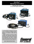
Gen-Eye Vista™ Video Pipe Inspection/Location System Operating Instructions Your Gen-Eye Video Pipe Inspection/ Location System is designed to give you years of trouble-free, profitable service. However, no machine is better than its operator. Read, understand and follow all safety warnings and instructions provided with the product. Failure to follow the warnings and instructions may result in electric shock and/or serious injury. Save all warnings and instructions for future reference. SAVE THESE INSTRUCTIONS! Gen-Eye Vista™ Video Pipe Inspection/Location System To reduce the risk of injury, user must read instruction manual. Failure to follow operating instructions could result in death or serious injury. Electric shock resulting in death can occur if you plug this machine into an improperly wired outlet. If the ground wire is electrified, you can be electrocuted by just touching the machine, even when the power switch is off. A ground fault circuit interrupter will not protect you in this situation. Use a UL listed tester to determine if the outlet is safe. WARNING Read all safety warnings and all instructions. Failure to follow the warnings and instructions may result in electric shock, fire and/or serious injury. Save all warnings and instructions for future reference. Replacement manuals are available upon request at no charge, or may be downloaded from our website, www.drainbrain.com. Instructional videos are available for download on our website, and may be ordered. If you have any questions or problems, please call General’s customer service department at 412-771-6300. Do not operate power tools in explosive atmospheres, such as in the presence of flammable liquids, gases, or dust. Power tools create sparks which may ignite the dust or fumes. SAVE THESE INSTRUCTIONS! These instructions are intended to familiarize all personnel with the safe operation and maintenance procedures for the Gen-Eye Vista Video Pipe Inspection/Location System. Always wear safety glasses and rubber soled, non-slip shoes. Use of this safety equipment may prevent serious injury. SAFETY SYMBOLS This is the safety alert symbol. It is used to alert you to potential personal injury hazards. Obey all safety messages that follow this symbol to avoid possible injury or death. DANGER indicates a hazard with a high level of risk which, if not avoided, will result in death or serious injury. WARNING indicates a hazard with a medium level of risk which, if not avoided, could result in death or serious injury. CAUTION indicates a hazard with a low level of risk which, if not avoided, will result in minor or moderate injury. 2 Gen-Eye Vista™ Video Pipe Inspection/Location System GENERAL POWER TOOL SAFETY WARNINGS 4. WARNING Read all safety warnings and all instructions. Failure to follow all instructions listed below may result in electric shock, fire, and/or serious injury. Equipment Use and Care SAVE ALL WARNINGS AND INSTRUCTIONS FOR FUTURE USE! Work Area Safety 1. Keep work area clean and well lit. Cluttered or dark areas invite accidents. 2. Do not operate power tools in explosive atmospheres, such as in the presence of flammable liquids, gases, or dust. Power tools create sparks which may ignite the dust or fumes. 3. Keep children and bystanders away while operating a power tool. Distractions can cause you to lose control. 1. Do not force equipment. Use the correct equipment for your application. The correct equipment will do the job better and safer at the rate for which it is designed. 2. Do not use the equipment if the switch does not turn it on and off. Any equipment that cannot be controlled with the switch is dangerous and must be repaired. 3. Disconnect the plug from the power source and/or battery pack from the power tool before making any adjustments, changing accessories, or storing. Such preventive safety measures reduce the risk of injury. 4. Store idle equipment out of reach of children and do not allow persons unfamiliar with the equipment or these instructions to operate the equipment. Equipment can be dangerous in the hands of untrained users. 5. Maintain equipment. Check for misalignment or binding of moving parts, breakage of parts and any other condition that may affect the equipment’s operation. If damaged, have the equipment repaired before use. Many accidents are caused by poorly maintained equipment. 6. Use the equipment and accessories in accordance with these instructions, taking into account the working conditions and the work to be performed. Use of the equipment for operations different from those intended could result in a hazardous situation. Electrical Safety 1. Power tool plugs must match the outlet. Never modify the plug in any way. Do not use any adapter plugs with earthed (grounded) power tools. Unmodified plugs and matching outlets will reduce risk of electric shock. 2. Avoid body contact with earthed or grounded surfaces such as pipes, radiators, ranges and refrigerators. There is an increased risk of electric shock if your body is earthed or grounded. Dress properly. Do not wear loose clothing or jewelry. Keep your hair, clothing, and gloves away from moving parts. Loose clothes, jewelry, or long hair can be caught in moving parts. 3. Do not expose equipment to rain or wet conditions. Water entering a power tool will increase the risk of electric shock. 4. Do not abuse the cord. Never use the cord carrying, pulling or unplugging the power tool. Keep cord away from heat, oil, sharp edges or moving parts. Damaged cords increase the risk of electric shock. 7. Use only accessories that are recommended by the manufacturer for your equipment. Accessories that may be suitable for one piece of equipment may become hazardous when used with other equipment. 5. When operating a power tool outdoors, use an extension cord suitable for outdoor use. Use of a cord suitable for outdoor use reduces the risk of electric shock. 8. Keep handles dry, clean, and free from oil and grease. This allows for better control of the equipment. 6. Keep all electric connections dry and off the ground. Reduces the risk of electric shock. 7. Do not touch plugs or tools with wet hands. Reduces the risk of electric shock. Service Ensure a qualified repair person services your equipment using only identical replacement parts to maintain the safety of the tool. This will ensure that the safety of the equipment is maintained. Remove the batteries and refer servicing to qualified service personnel under any of the following conditions: Personal Safety 1. 2. 3. Stay alert, watch what you are doing and use common sense when operating a power tool. Do not use a power tool while you are tired or under the influence of drugs, alcohol, or medication. A moment of inattention while operating power tools may result in serious personal injury. Use personal protective equipment. Always wear eye protection. Protective equipment such as dust mask, non-skid safety shoes, hard hat, or hearing protection used for appropriate conditions will reduce personal injuries. Do not overreach. Keep proper footing and balance at all times. This enables better control of the power tool in unexpected situations. 3 • • If liquid has been spilled or objects have fallen into product. • • If the product has been dropped or damaged. If the product does not operate normally when following the operating instructions. When the product exhibits a distinct change in performance. Gen-Eye Vista™ Video Pipe Inspection/Location System FEATURES SPECIFIC SAFETY INFORMATION WARNING This section contains important safety information that is specific to the Gen-Eye Vista. Read these precautions carefully before using the Gen-Eye Vista to reduce the risk of electrical shock, fire, or other serious injury. 1 2 SAVE ALL WARNINGS AND INSTRUCTIONS FOR FUTURE USE! 1. 2. 3. 4. 5. 6. 7. 8. 11 3 The equipment is intended for indoor use when used with the AC power supply. When powered by battery, protect it from exposure to weather. This product is not water resistant. Do not expose the equipment to moisture or rain. Water entering the unit housing can increase the risk of safety hazards and electrical shock. Only the camera and cable in a Gen-Eye Pipe Inspection Reel are water-resistant. 5 12 4 13 14 15 16 6 7 8 10 An improperly grounded electrical outlet can cause electrical shock and/or severely damage equipment. Always check work area for a properly grounded electrical outlet. Presence of a three-prong or GFCI outlet does not ensure that the outlet is properly grounded. If in doubt, have the outlet inspected by a licensed electrician. Do not operate this equipment if operator or Gen-Eye Vista is standing in water. Operating the Vista while in water increases the risk of electrical shock. 9 17 18 19 The Vista is not waterproof. It is dust resistant and splashresistant. Only the camera and push rod are waterproof. Do not expose the equipment to water or rain. This increases the risk of electrical shock. Do not use where a danger of high voltage contact is present. The equipment is not designed to provide high voltage protection and isolation. Read and understand this operator’s manual, the reel operator’s manual, the instructions for any other equipment in use and all warnings before operating the Vista. Failure to follow all instructions and warnings may result in property damage and/ or serious personal injury. Always use appropriate personal protective equipment when handling and using equipment in drains. Drains may contain chemicals, bacteria, and other substances that may be toxic, infectious, cause burns or other issues. Appropriate personal protective equipment always includes safety glasses and may include drain cleaning gloves or mitts, latex or rubber gloves, face shields, goggles, protective clothing, respirators, and steel toed footwear. If using drain cleaning equipment at the same time as drain inspection equipment, only wear leather gloves. Never grasp the rotating drain cleaning cable with anything else, including other gloves or a rag. These items could become wrapped around the cable and cause serious injury. 1. 2. 3. 4. 5. 8” LCD Color Monitor Camera Test Port Reel Connection LED Dimmer Control Voice Over Microphone & Switch 6. DC Power Input 7. AC Power Input 8. Power Switch 9. DVR Recorder 10. Full Keyboard With 9 Pages of Memory 4 11. 12. 13. 14. 15. 16. 17. 18. 19. Fuses SD Card Reader Low Battery Alarm Silencer Reel Selector Switch Battery Level Indicator Video/Audio Out Jacks USB Port SD Card Reader Controller 4 hr. Battery (not shown) Gen-Eye Vista™ Video Pipe Inspection/Location System AC Power Input 8” LCD COLOR MONITOR Plug the socket end of the AC cord into the AC socket on the panel of the Command Module. When using 120 volts AC, care should be taken to ensure that it is plugged into a properly grounded receptacle to prevent damage to the unit. Be sure that “Video 1” is selected. SD CARD READER AND SD CARD READER CONTROLLER The SD Recorder is located in the control panel, to the right of the monitor. 1. Make sure you have established a live image on the monitor prior to recording. 2. Insert an SD card into the SD card recorder. Slide the card into the slot, metal tabs to the right. Press the card all the way in, then release. 3. To start the recording process, press the [REC] button on the SD Recorder Remote Control. 4. To end the recording, press the [STOP] button on the SD Recorder Remote Control. 5. You may playback the recording using the Remote Control. 6. To remove the SD card, press the card into the slot and release. The card will extend out far enough to remove. DC Power Input Plug the socket end of the DC cord into the DC socket on the panel of the Command Module. Plug the unit into your vehicle’s cigarette lighter for 12VDC. It is recommended that the vehicle engine should be running to operate the camera system. THE AC OR DC CORD SHOULD ALWAYS BE PLUGGED INTO THE SD COMMAND MODULE FIRST, THEN INTO THE WALL OR 12VDC SOCKET. NEVER PLUG INTO THE AC SOCKET OR DC SOURCE FIRST. INTERNAL BATTERY - BATTERY STRENGTH INDICATOR - LOW BATTERY ALARM The Vista includes a rechargeable battery for operating in a remote location far from a power source. The battery lasts up to 4 hours, depending on air temperature and condition of the battery. See SD Recorder manufacturer’s manual for further instructions. DVD RECORDER The Battery Strength Indicator will show three green LED’s when fully charged. Yellow LED’s indicate the battery is partially charged. The red LED’s will strobe and the Low Battery Alarm will sound when the battery is nearly depleted. Press Alarm Silencer to stop the alarm. It will ring again in 3 minutes to remind you to recharge the battery. To access the DVD Recorder, lift the knob to the right of the keyboard to open the storage compartment. 1. Press the DVD power button. 2. Press the DVD eject button. 3. Place a blank, DVD-R into the disc tray, recording side down, and push the disc tray to close it. Note: Do not touch the recording side of the disc. Battery Strength Indicator - Table 1 Indicator Color Battery Strength See DVD Recorder manufacturer’s manual for further instructions. USB PORT Green Fully Charged Yellow Partially Charged Red (Strobing) Nearly Depleted Low Battery Alarm Low Battery Alarm will sound. Press reset to silence alarm for 3 minutes. The battery can be recharged from either an AC outlet, or from the DC outlet in your car or truck. Recharging time is approximately 3 hours, depending upon air temperatures and the condition of the battery. The battery does not have to be deep cycled, but the battery may have to be replaced over time depending on usage and conditions. To record video directly to a computer via USB cord. Do not charge the battery if the air temperature is below 30° F or above 104° F. 5 Gen-Eye Vista™ Video Pipe Inspection/Location System CAMERA TEST PORT DISTANCE COUNTER Use this connector to troubleshoot video and light problems in the field. (See Maintenance Section for details.) Make sure the Reel Selector switch is set for the reel you are using. Before starting the inspection, place the camera in the line and zero your counter. This is your starting point for measurements. TITLER/KEYBOARD The Vista has a built-in full keyboard titler. It gives you nine pages of text to easily add your company name and job location to your inspection videos. 1. To set the counter to +0000.0, press [F4] followed by [ENTER]. 2. To set the counter to a preset value, press [F4], then press either [− + ||] or [− − ||] followed by five digits (numbers). To save a page to memory: SETTING TIME/DATE 1. Go to the page you wish to save by pressing [ESC] followed by 1-9 (example: [ESC]+[5]). 1. Hold [CTRL] and press [D]. −YYMMDDHHMMSSam|| appears on the screen. 2. Type text on screen. 2. 3. Press [F5] to save screen text to selected page. Type in the correct time and date in this order: year, month, day, hour, minutes, seconds, am/pm (‘a’ for AM and ‘p’ for PM). 3. If you wish to quit, simply hit the [ENTER] button and date and time entry line will disappear. 4. Note: The clock mode is 12 hour - i.e., 01 to 12. KEYBOARD/COUNTER OPERATING INSTRUCTIONS LED DIMMER CONTROL You can adjust the camera LED light level by using the Dimmer located on the control panel. Rotate knob clockwise to increase brightness. KEY FUNCTION F1 Cursor ON/OFF F2 Clear screen and place cursor at home position (i.e. top left corner) F4 Press [F4] followed by [+] or [-] and five digits. Press [ENTER] to confirm F5 Save current on-screen text to memory page Connect the interface cord from large or mini-reel to Reel Connector, located on the control panel. F6 Time and Date ON/OFF toggle VIDEO/AUDIO OUT JACKS [ENTER] Move cursor to next line Backspace erases letter and goes back one position. [ESC] [ESC] followed by 1-9 recalls saved pages on screen [CTRL]-D Set Time/Date. [ENTER] to quit [CTRL]-C Reposition counter in one of the four corners and the bottom center of the screen [CTRL]-B Type black characters with white border [CTRL]-F Turn flashing characters ON [CTRL]-N Turn flashing characters OFF [CTRL]-W Type white characters VOICE OVER MICROPHONE & SWITCH The Vista includes an internal microphone so you can add commentary to your videos. Turn the switch ON to activate the Mic and OFF to mute it. REEL CONNECTION Video and audio can be recorded on an external device. Use the ports located on the control panel to connect to the external device. FUSES Fuses are located on the control panel underneath the 8” LCD Color Monitor. STORAGE COMPARTMENT (UNDER KEYBOARD) Lift the knob located to the right of the keyboard to open compartment. AC and DC power cords, SD Card, Wrench, and other accessories are stored in this compartment. PADDED CASE The padded case protects the electronics inside. The Command Module should not be used in wet locations or in the rain, as moisture may cause damage to the unit. 6 Gen-Eye Vista™ Video Pipe Inspection/Location System CONNECTING COMMAND MODULE TO DOCKING ARM 1. Loosen the knob on the lower docking arm tube and slide the upper portion out. 2. Place the closed Vista Command Module upside down on a surface. INTERNAL 512 Hz TRANSMITTER The camera system includes a 512 Hz transmitter, located in the spring behind the camera. When the Command Module is turned on, the transmitter will automatically activate. Care should be taken when bending and twisting the spring more than 180 degrees, as damage to the transmitter may occur. CARE SHOULD BE TAKEN WHEN USING THE TRANSMITTER IN THE SPRING AS EXCESSIVE BENDING AND TWISTING MORE THAN 180 DEGREES MAY DAMAGE THE UNIT. 3. Align the screw and guide pin in the block to the holes in the bottom of the Command Module. 4. Thread the screw into the base and tighten firmly. 5. Hold the Command Module and Docking Arm Assembly above the reel and align the upper tube with the lower tube, which is mounted on the reel. 6. Slide the upper tube into the lower tube to desired position and tighten knob. SKIDS If the pipe is large enough, be sure to use the Trap Skid. It keeps the camera centered in the pipe for a better view while reducing the drag on longer runs. Standard reels include both 3” and 6” trap skids that protect the camera from abrasion as it slides through cast iron traps. Mini-Reels include only the 3” trap skid. An optional 3-in-1 skid set for 4”, 6” and 8” lines, and a Universal Roller Skid are also available. Note: the Gen-Eye Vista and Gen-Eye SD Docking Arms are NOT interchangeable. TO INSTALL TRAP SKID 1. Clean the camera head of any debris. 2. Slide the trap skid over the front of the camera so that the lip in the skid presses firmly against the front of the camera. 3. Tighten the set screws only until they touch the camera body. Do not over-tighten, as you could damage the camera housing. OPERATING INSTRUCTIONS SET-UP Table 2—Reel Selection Guide Reel Type Pipe Sizes Lengths Available 1. Place the camera system on a level surface near the drain line to be inspected. 2. Release the latch and open the Command Module case. Unwind the Interface cord from the reel and plug it into the reel connector on the panel of the Command Module. Standard Reel 3” to 10” (75 to 250mm) 200, 300. or 400 ft. (60, 90 or 120m) 3. Mini Reel 1-1/2” to 4” (38 to 100mm) 100 or 200 ft. (30 or 60m) 4. Be sure that the Reel Selector Switch matches the reel you are using - standard or mini - so that the distance counter measures accurately. 5. Plug the AC cord into the AC connection, or the DC cord into the DC connection, on the panel of the Command Module. 6. Turn on the Vista by switching the Power Switch to AC for AC power, or DC for DC power from your truck. 7. If using the internal battery, turn on the unit by switching to DC. Remember to turn off the unit when not in use to conserve battery power. 8. Turn on the LCD screen by pressing the monitor power button (Iocated on the front of the monitor). SELF-LEVELING COLOR CAMERA The self-leveling color camera automatically keeps the picture right side up as the camera glides through the line. You always have an upright picture on the monitor, making it easier for you and your customer to follow the action. The self-leveling camera is only available for standard size reels. 7 Gen-Eye Vista™ Video Pipe Inspection/Location System OPERATION 11. When you can only receive the signal in a small, one-foot square area, you’ve located the camera. Mark the spot. 1. Pull the reel lock pin to release, then loosen the drag brake on the side of the reel. 2. Pull the camera from the reel and slowly push it into the drain line. Make sure the spring does not kink or double back on itself. 3. Be sure that the push rod is rated for the pipe you are inspecting. Be careful not to force the camera around tight bends. If you see an obstruction, STOP. Do not attempt to clear the pipe by using the camera head. Always use the proper tool for the job. 4. Once the camera is in the pipe, adjust the camera lights with the LED Dimmer control on the panel of the Command Module to the level that produces the best picture with the least amount of light. This will vary depending on pipe conditions. You may also adjust the brightness and contrast controls on the monitor. 5. Push slowly and carefully during the inspection. Take note of possible hazards, root entanglements, or breaks in the pipe that may trap or damage the camera on retrieval. Radiated Signal Note: It is helpful to jet the line first to give the camera the best possible view of the pipe. Cameras see under water as well as you do. If the water is murky, the picture from the camera will be too. Camera An instructional video is available at www.drainbrain.com. Locator Ghost Signal Peak Signal Ghost Signal CAMERA LOCATION 1. Turn the Gen-Eye Vista power switch to ON. DEPTH MEASUREMENT Tip: It’s much easier to locate the camera when it’s closer to the drain opening than when it’s 100 feet away. Push the camera five or ten feet into the line, then do your first location. Mark the spot and push the camera ahead another five or ten feet, then repeat. When you’re done, you’ll have the whole line traced and marked. 1. Recheck the camera location using the steps outlined above. 2. Rest the tip of Locator on the ground, holding it vertically above the pinpointed position of the camera head. 3. Press the DEPTH button. The LCD screen will indicate the depth of the camera. 4. You can select the unit of measurement (feet, inches, meters, centimeters) by pressing the DEPTH button and the DOWN arrow at the same time. 2. Switch the Locator ON and check that the battery level indicator shows at least one bar. Replace batteries as needed. 3. Make sure the Locator is set for the same frequency as the transmitter by pressing the Frequency button (FREQ) until the desired frequency appears on the display. (The camera transmits at 512 Hz.) 4. Press Antenna Select (ANT SEL) so that the indicator arrow points to TWIN PEAK. 5. Press the UP arrow so that the gain bar is at the maximum setting. 6. Hold the Locator blade vertical and in line with the camera head (handle of the Locator at 90 degrees to the camera head). If you are not sure of the direction of the pipe, hold the locator above the drain opening and rotate it until you obtain the maximum signal. Note: An indication of four dashes on the display can be caused by too much or too little signal strength. Adjust the gain and recheck the depth measurement. See complete Locator instruction manual for more information. An instructional video is available at www.drainbrain.com. Note: The camera must be stationary to be precisely pinpointed. 7. Move the Locator forward and backward, and side to side along the camera path until you obtain a peak response on the display. 8. If the display indicates a maximum signal of 100, reduce the gain by pressing the DOWN arrow to keep the display at approximately 50% – 70%. 9. Repeat step 7 and 8 as you narrow your search area. 10. A small ghost signal may appear in front and behind the peak reading. Lower the gain button until you receive only one signal. 8 Gen-Eye Vista™ Video Pipe Inspection/Location System CAMERA REMOVAL MAINTENANCE DISCONNECT MACHINE FROM POWER SOURCE BEFORE REMOVING CAMERA FROM, OR RECONNECTING CAMERA TO, REEL ASSEMBLY! DISCONNECT MACHINE FROM POWER SOURCE BEFORE PERFORMING MAINTENANCE ON MACHINE! The camera is manufactured for harsh environments; however, it should be treated carefully as damage may occur if dropped or butted severely against the pipe or any other hard surface. The stainless steel camera housing is made to protect the camera and electronics; however it can be damaged by harsh use. This may cause failure of the watertight O-ring seals and can cause the camera to fail. Check the connection after each use to ensure that the screws have not loosened during the inspection. The camera housing and viewing lens should be checked thoroughly for signs of damage after each use, and repaired if needed prior to further use. To prevent degradation of the video picture, clean and check the camera lens and lights after every use for damage to the lens or light covers and to prevent a build up of dirt and grime. TO PREVENT DAMAGE TO THE CAMERA AND/OR SYSTEM, DISCONNECT POWER FROM THE COMMAND MODULE BEFORE REMOVING OR RECONNECTING THE CAMERA TO THE REEL. The camera is not user serviceable. Servicing should be left to qualified personnel. (Contact the factory if you have questions.) In the event the camera needs to be returned to the factory, remove the camera using the following instructions: 1. The camera and spring assembly is attached to the Push-Rod with three (3) 4-40 x 1/2” stainless steel hex socket cap screws. Remove the screws using the Xcelite allen wrench supplied with the unit. Screws should be removed carefully and simultaneously. Each screw should be turned approximately one full turn, alternatively, so as not to damage the connector. While backing out each screw, hold the coupling together until all three screws are out. Then, unplug the camera from the Push-Rod, taking care not to lose the O-ring or screws. 2. After unplugging the camera, inspect the O-ring for damage or wear. If worn, replace with a new one. When replacing, make sure there is no dirt in the connection area, as this will prevent it from sealing properly. Apply silicone grease or petroleum jelly to the O-ring for a proper seal. 3. To reconnect, carefully align the camera assembly connector and the Push-Rod coupling. Push the connectors together and replace the screws. If the connectors do not align properly, turn the camera body slowly while slightly pushing the two connectors together until you feel them align. CAMERA CLEANING After every use, the camera should be cleaned and checked for possible damage that may have occurred during the inspection. External scuffing of the camera housing is normal and should be of no concern; however, you can protect the camera and help it slide around elbows more easily by using the trap skid. The camera lens is made of sapphire and should be cleaned with a soft, damp cloth. Grease, dirt, or scratches will affect the quality of the video picture. PUSH-ROD & REEL ASSEMBLY CLEANING The Push-Rod and Reel should be kept clean. When rewinding the Push-Rod back in to the reel after an inspection, it is good practice to use a clean rag to wipe off debris. DO NOT FORCE THE CONNECTORS TOGETHER. DAMAGE MAY OCCUR TO THE CONNECTORS. Caution: When cleaning Push-Rod and Reel Assembly, DO NOT USE A POWER WASHER. Water may get into the unsealed areas, such as the hub assembly and slip ring housing and cause damage, voiding the warranty. 4. LED LIGHT REPLACEMENT The cameras use LED lights that cannot be replaced by the operator. Unless physically damaged or extreme voltage is applied to them, the LED’s should last indefinitely. If replacement is necessary, the camera should be returned to the factory. CAMERA FOCUS All Gen-Eye cameras are pre-focused at the factory from approximately 3” to infinity. Should focus adjustments be require, please contact the factory. CAMERA TEST PORT Use this connector to trouble shoot video and light problems. 1. Disconnect the system from the power source. 2. Remove camera from Push-Rod Assembly. (See Camera Removal Section) 3. Plug camera into Test Port. 4. If lights or video are working, the problem is likely to be in the Push-Rod or reel. If the lights or video are not working, the problem is likely to be in the camera. (Always check the fuses first.) When removing the camera assembly for any reason (to replace seals, etc.), always do so in a clean environment. Clean the camera first, before disassembly. Take extra precaution to avoid getting dirt into the camera body and any mating components or connectors. FUSES The Command Module contains three replaceable fuses. Fuses for line voltage (3 amp), camera (.5 amp), and camera LED lights (.25 amp) are located on the main panel under the monitor. Should replacement become necessary, replace only with the same value and type as the original. Never substitute fuses as damage may occur and void the warranty. 9 Gen-Eye Vista™ Video Pipe Inspection/Location System Bad or Grainy Picture TROUBLESHOOTING COMMAND MODULE Check the camera lens for dirt, grime, scratches or other foreign matter. No Picture AND No Lights: Check the Light Head to see if it is not supplying sufficient light due to weak, dirty, or burned out bulbs. Check to see if the Main Power switch is ON. Check that the SD Recorder power is ON. Check that Monitor Power is ON and SOURCE is set to the proper position. Check to make sure that the camera lens is not covered or looking at a surface that provides no detail, therefore any image detail. Check all connections and connectors from the camera back to the Command Module, including the cable reel. Disconnect main power and contact the factory service department. Check for external electrical noise being radiated by outside sources, such as a power station, etc. Check the cable for possible breaks or intermittent open circuits by flexing the cable. Remove the camera from the cable assembly and plug it into the Camera Test Terminal. Disconnect the main power source and contact the factory service department. Picture BUT No Lights: Not Recording Check if Main Power switch is ON, and in correct position. Check to see if LIGHT power switch is ON and intensity control is turned up. Check cable for possible breaks or intermittent open circuits by flexing the cable. Always check record and play functions prior to inspections to ensure that the SD/DVD recorder is working properly. Check that there is enough memory available on the SD card/disc. Check whether the inserted SD card/disc is formatted correctly. No Picture, Lights OK Check whether the disc has already been used for recording by another DVD recorder. (DVD recording) Check Monitor power switch is ON. Check to make sure the power source is “live” (for 120 volt AC) or check to see if the light is lit on the cigarette lighter plug (for 12 volt DC). Check whether you have inserted a recordable disc. (DVD recording) Check to see if the CAMERA power fuse has “tripped”. If so, replace with same value. Check that the SD card hasn’t been “locked”. Disconnect the main power source and contact the factory service department. Check to see if the monitor brightness and contrast controls are turned up. Check the interface cord for possible damage or intermittent problem by flexing the cable. FOR ALL OTHER FUNCTIONS RELATIVE TO THE SD/DVD RECORDER OR MONITOR UNIT, PLEASE CONSULT YOUR RECORDER OR MONITOR OWNER’S MANUAL. Check the cable for possible breaks or intermittent open circuits by flexing the cable. Remove the camera from the cable assembly and plug it into the Camera Test Terminal. Disconnect the main power and contact the factory service department. Dark Picture FOR MORE INFORMATION CONTACT THE DRAIN BRAINS® AT: Check to see if the monitor brightness and contrast controls are turned up. Check the Light Head to see if it is not supplying sufficient light due to weak, dirty, or burned out bulbs. Check to see if the Light Head intensity control is turned up. Disconnect the main power source and contact the factory service department. 412-771-6300 or 800-245-6200 www.drainbrain.com [email protected] 10 Gen-Eye Vista™ Video Pipe Inspection/Location System GENERAL'S LIMITED WARRANTY General’s Gen-Eye Vista video pipe inspection/location system carries a two-year warranty against defect in materials except as noted below. Should any part break or fail to work properly in the two years following purchase, it will be repaired or replaced at our discretion at no charge. Damage due to negligence, improper usage, failure to follow instructions, accidents, or alteration from original design is not covered by this warranty. In order to handle any adjustment with a minimum of delay, please follow this procedure: 1. Return the part to your wholesaler, and have them notify us immediately, with complete information on the problem. 2. We must have the serial number, the date of purchase, and the name of the wholesaler from whom you tool was purchased. To activate your Gen-Eye warranty, your warranty card, which has this information, must be filled out and sent to us immediately after your machine is purchased. 3. We will then advise your wholesaler if the part should be returned to us and assign a return goods authorization (RGA) number. Ship freight prepaid, and you will be compensated for these charges if it is determined that the part is defective. If repairs are necessary due to conditions beyond our control, or if the item is out of warranty, we will do the work at the lowest possible cost, but a charge will be made. This warranty is made in place of all other warranties, express, statutory or implied, including those of merchantability and of fitness for purpose. General shall not be responsible for any incidental or consequential damages. This warranty gives you specific legal rights, and you may also have other rights which vary from state to state. Some states do not allow the exclusion of limitation of incidental or consequential damages, so these limitations may not apply to you. 11 Gen-Eye Vista™ Video Pipe Inspection/Location System General Wire Spring Co, 1101 Thompson Avenue McKees Rocks, PA 15136 412-771-6300 www.drainbrain.com © General Wire Spring Co. 2012 C-GVOI-1212