1
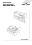
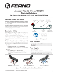
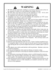
I-95™
Operating Instructions
For 1-1/4” through 4”
(30mm—100mm)
Your I-95 is designed to give you years
of trouble-free, profitable service. However, no machine is better than its operator.
Read, understand and follow all safety
warnings and instructions provided with
the product. Failure to follow the warnings
and instructions may result in electric
shock and/or serious injury. Save all warnings and instructions for future reference.
SAVE THESE INSTRUCTIONS!
I-95™
Electric shock resulting in
death can occur if you plug
this machine into an improperly wired outlet. If the ground
wire is electrified, you can be
electrocuted by just touching
the machine, even when the
power switch is off. A ground
fault circuit interrupter will not protect you in this situation. Use a
UL approved tester to determine
if the outlet is safe.
WARNING!
Read and understand all
instructions. Failure to follow all instructions
listed below may result in electric shock, fire
and/or serious personal injury. Replacement
manuals are available upon request at no
charge, or may be downloaded from our website, www.drainbrain.com. Instructional videos
are available for download on our website, and
may be ordered. If you have any questions or
problems, please call General’s customer
service department at 412-771-6300.
Do not operate power tools in
explosive atmospheres, such
as in the presence of flammable liquids, gases, or dust.
Power tools create sparks which
may ignite the dust of fumes.
SAVE THESE INSTRUCTIONS!
These instructions are intended to
familiarize all personnel with the safe
operation and maintenance
procedures for the I-95.
Only wear leather gloves.
Never use any other type of
glove, such as cloth, rubber, or
coated gloves. Never grasp a
rotating cable with a rag.
These items could become
wrapped around the cable and
cause serious injury.
SAFETY SYMBOLS
This is the safety alert symbol. It is
used to alert you to potential personal
injury hazards. Obey all safety messages that follow this symbol to avoid
possible injury or death.
Always wear safety glasses
and rubber soled, non-slip
shoes. Use of this safety equipment may prevent serious injury.
DANGER indicates a hazard with a high level of risk
which, if not avoided, will result in death or serious injury.
Never operate machine with
belt guard removed. Fingers
can get caught between belt and
pulley.
WARNING indicates a hazard with a medium level of risk
which, if not avoided, could result in death or serious injury.
Do not overstress cables.
Overstressing cables may cause
twisting, kinking, or breaking of
the cable and may result in serious injury.
CAUTION indicates a hazard with a low level of risk which,
if not avoided, will result in minor or moderate injury.
2
I-95™
GENERAL SAFETY RULES
Personal Safety
1.
Stay alert, watch what you are doing and use common sense
when operating a power tool. Do not use tool while tired or
under the influence of drugs, alcohol, or medication. A moment of inattention while operating power tools may result in
serious personal injury.
2.
1. Keep work area clean and well lit. Cluttered benches and dark
areas invite accidents.
Dress properly. Do not wear loose clothing or jewelry. Contain long hair. Keep your hair, clothing, and gloves away
from moving parts. Loose clothes, jewelry, or long hair can be
caught in moving parts.
3.
2. Do not operate power tools in explosive atmospheres, such as
in the presence of flammable liquids, gases, or dust. Power
tools create sparks which may ignite the dust or fumes.
Avoid accidental starting. Be sure switch is off before plugging in. Carrying tools with your finger on the switch or plugging
in tools that have the switch on invites accidents.
4.
Remove adjusting keys or switches before turning the tool
on. A wrench or key that is left attached to a rotating part of the
tool may result in personal injury.
5.
Do not overreach. Keep proper footing and balance at all
times. Proper footing and balance enables better control of the
tool in unexpected situations.
6.
Use safety equipment. Always wear eye protection. Dust
mask, non-skid safety shoes, hard hat, or hearing protection
must be used for appropriate conditions.
WARNING
Read and understand all instructions. Failure to follow all instructions listed below may result in electric shock, fire, and/or
serious injury.
SAVE THESE INSTRUCTIONS!
Work Area
3. Keep bystanders, children, and visitors away while operating
a power tool. Distractions can cause you to lose control.
Electrical Safety
1. Grounded tools must be plugged into an outlet, properly installed and grounded in accordance with all codes and ordinances. Never remove the grounding prong or modify the
plug in any way. Do not use any adapter plugs. Check with a
qualified electrician if you are in doubt as to whether the outlet is properly grounded. If the tool should electrically malfunction or break down, grounding provides a low resistance path to
carry electricity away from the user.
Tool Use and Care
1.
2. Avoid body contact with grounded surfaces such as pipes,
radiators, ranges and refrigerators. There is an increased risk of
electric shock if your body is grounded.
Use clamps or other practical way to secure and support the
workpiece to a stable platform. Holding the work by hand or
against your body is unstable and may lead to loss of control.
2.
3. Do not expose power tools to rain or wet conditions. Water
entering a power tool will increase the risk of electric shock.
Do not force tool. Use the correct tool for your application.
The correct tool will do the job better and safer at the rate for
which it is designed.
3.
4. Do not abuse the cord. Never use the cord to carry the tools
or pull the plug from an outlet. Keep cord away from heat, oil,
sharp edges or moving parts. Replace damaged cords immediately. Damaged cords increase the risk of electric shock.
Do not use tool if switch does not turn it on or off. Any tool
that cannot be controlled with the switch is dangerous and must
be repaired.
4.
Disconnect the plug from the power source before making
any adjustments, changing accessories, or storing the tool.
Such preventative safety measures reduce the risk of starting the
tool accidentally.
5.
Store idle tools out of reach of children and other untrained
persons. Tools are dangerous in the hands of untrained users.
6.
Maintain tools with care. Keep cutting tools sharp and clean.
Properly maintained tools, with sharp cutting edges are less likely
to bind and are easier to control.
7.
Check for misalignment or binding of moving parts, breakage of parts, and any other condition that may affect the
tool’s operation. If damaged, have the tool serviced before
using. Many accidents are caused by poorly maintained tools.
8.
Only use accessories that are recommended by the manufacturer for your model. Accessories that may be suitable for
one tool may become hazardous when used on another tool.
5. When operating a power tool outside use an outdoor extension cord marked “W-A” or “W”. These cords are rated for outdoor use and reduce the risk of electric shock.
6. Test the Ground Fault Circuit Interrupter (GFCI) provided with
the power cord to insure it is operating correctly before operating machine. Machine must have a properly functioning ground
fault circuit interrupter on the power cord. GFCI reduces the risk of
electric shock.
7. Extension cords are not recommended unless they are
plugged into a Ground Fault Circuit Interrupter (GFCI) found
in circuit boxes or outlet receptacles. The GFCI on the machine
power cord will not prevent electric shock from the extension
cords.
8. Only use proper three-wire extension cords in good condition
which have three-prong grounding plugs and three-pole receptacles which accept the tool’s plug. Use of damaged, inferior, or other extension cords will not ground the tool. Increases
the risk of electric shock and bodily injury or death.
Service
9. Keep all electric connections dry and off the ground. Reduces
the risk of electric shock.
10. DO NOT touch plugs or tools with wet hands. Reduces the risk
of electric shock.
3
1.
Tool service must be performed only by qualified repair personnel. Service or maintenance performed by unqualified repair
personnel could result in a risk of injury.
2.
When servicing a tool, use only identical replacement parts.
Follow instructions in the Maintenance section of this manual. Use of unauthorized parts or failure to follow Maintenance
Instructions may create a risk of electric shock or injury.
I-95™
SPECIFIC SAFETY RULES
3.
4.
This is the safety alert symbol. It is used to alert
you to potential personal injury hazards. Obey all
safety messages that follow this symbol to avoid
possible injury or death.
If light does not go out when test button is pushed, equipment
should not be used until proper repairs can be made.
To restore power after test, push reset button. With the reset
button depressed, if the machine doesn't start, stops while running, or if the operator experiences a mild shock, do not use the
machine! Tag the machine out of service and take it to a motor
repair center or return it to the factory for repairs.
Electric shock resulting in death can occur if you
plug this machine into an improperly wired outlet. If
the ground wire is electrified, you can be electrocuted
by just touching the machine, even when the power
switch is off. A ground fault circuit interrupter will not
protect you in this situation. Use a UL approved tester to
determine if the outlet is safe.
THE SECTION OF CORD BETWEEN THE WALL PLUG
AND THE GFCI IS NOT IN THE PROTECTED CIRCUIT.
FEATURES
Do not overstress cables. Overstressing cables may
cause twisting, kinking, or breaking of the cable and may
result in serious injury.
1.
Do not overstress cables. Keep leather-gloved hand on the
cable for control when machine is running. Overstressing cables
because of an obstruction may cause twisting, kinking, or breaking of the cable and may result in serious injury.
3.
Place the machine at a distance not greater than two feet
from the opening. Greater distances can result in cable twisting
or kinking.
4.
Machine is designed for ONE-PERSON operation. Operator
must control foot switch and cable.
5.
Be careful when cleaning drains where cleaning chemicals
have been used. Avoid direct contact with skin and eyes. Drain
cleaning chemicals can cause serious burns as well as damage
the cable.
6.
Do not operate machine if operator or machine is standing
in water. Will increase risk of electrical shock.
7.
Wear safety glasses and rubber soled, non-slip shoes. Use
of this safety equipment may prevent serious injury.
8.
Before starting each job, check that the cable is not broken
or kinked, by checking for wear or breakage. Always replace
worn out (kinked or broken) cables with genuine GENERAL replacement cables.
9.
Chuck
Cover
Only wear leather gloves. Never use any other type of glove,
such as cloth, rubber, or coated gloves. Never grasp a rotating
cable with a rag. These items could become wrapped around the
cable and cause serious injury.
2.
Chuck Handle/
Lifting Handle
Rear Guide
Hose
Cable
Motor Switch
Cutter
Cover
Retaining
Knob
NOTE: Do not operate machine if warning labels on the Motor Housing and power cord are missing or illegible.
Cables and Connectors
Your machine comes with “R” type cable connectors to match Ridgid ®
-type cables.
To couple “R” cables, put the T-shaped
slot in the female connector next to the
T-shaped male connector. Slide the
two together and the spring pin will
snap into place.
Only use this tool in the application for which it was designed. Follow the instructions on the proper use of the machine. Other uses or modifying the drain cleaner for other applications may increase risk of injury.
To disconnect, push the coupling key into
the hole just below the slot in the female
connector, then slide connectors apart
Ground Fault Circuit Interrupter (GFCI)
Your machine is equipped with a ground fault circuit interrupter, which
protects you against shock if a short circuit should occur. Check that
receptacle is properly grounded. Test the GFCI before each use.
1. Plug into 120-volt receptacle.
2. Push test button. Indicator light will go out and power to machine
should cut off.
4
I-95™
OPERATION
Sectional Cables Compatible with Ridgid® Cables
7.5R-7
5/8” x 7-1/2 ft. Close-Wound
7.5R-8
5/8” x 7-1/2 ft. Open-Wound
15R-10
7/8” x 15 ft. Open-Wound
15R-10-P
7/8” x 15 ft. Proflex
Set-Up - 5/8” and 7/8” Cables
MAKE SURE THE MOTOR SWITCH
IS IN THE ‘OFF’ POSITION!
Adjustable Chuck Set-Up
The chuck has two sets of notches, one for 5/8” cables and one for
7/8” cables. Use the following procedure to switch between cable
sizes:
General makes cables and cutters to fit equipment manufactured by others. We have no affiliation with these companies.
1. Remove the chuck cover by unscrewing retaining knob.
Cable Application Chart (Table 1)
Cable Size
Pipe Size
Typical Applications
Max.Distance
2. The chuck cone has three small notches for 5/8” cables and three
large ones for 7/8” cables. They are marked accordingly.
5/16”
(Container)
1-1/2””
to 2”
Small lines, tubs,
showers
50 ft.
3. Squeeze the three jaws together while rotating the chuck cone to
the desired setting.
3/8”
(Container)
2” to 3”
Sinks, basins, small
drains
35 ft.
5/8”
Sections
1-1/4” to
3”
Roof stacks, small
drains
125 ft.
7/8”
Sections
2” to 4”
Medium Lines, Floor
Drains
125 ft.
4. Replace the chuck cover and screw in the retaining knob.
Cutter Application Chart (Table 2)
Cutter
Cat. #
Machine Set-Up
1. Place machine at a distance of
not greater than two feet (.6m) of
drain opening. If you can’t place
the machine this close to the
drain opening, run the cable
through a pipe or a metal guide
tube to prevent cable whipping.
Typical Applications
Cutters for 5/8” Cables
Arrow
Head
1-1/2”
U-Cutter
Boring
Gimlet
Small
Retrieving
Tool
R-AH
R-1-1/2UC
Starting Tool, ideal for cutting
and scraping.
Finishing tool, works well in
grease stoppages.
R-BG
To remove or retrieve loose
objects.
R-RTR-1
To remove or retrieve loose
objects.
2. Attach Rear Guide Hose (66-RGH) by aligning knob on guide hose
with indent on rear of machine and tighten.
3. Slide cable, female connector first, into front of machine. Never
use more than one cable at a time.
4. Insert cutting tool into male connector at other end of cable. Start
with the small cutters to get the line open. After the line is opened,
follow with larger blades, which scrape the inside walls of the pipe,
assuring a real cleaning job.
Cutters for 7/8” Cables
Spear
Head
R-SHD-10
Starting Drill—gets water flowing.
2”
U-Cutter
R-2UC-10
For Cutting and Scraping
R-3UC-10
For Cutting and Scraping
R-HA-10
To remove or retrieve loose
objects
R-RTR-2
For removing loose objects or
broken cables.
3”
U-Cutter
Hook
Auger
Large
Retrieving
Tool
OPERATION - 5/8” and 7/8” CABLES
MAKE SURE THE MOTOR SWITCH
IS IN THE ‘OFF’ POSITION!
1. Push the cable into the drain opening as far as it will go. Then pull
an additional foot of cable from the machine so that an arc is
formed.
2. Turn the motor switch to the forward position. The motor will start
running.
3. Put one gloved hand on the cable then push the chuck handle
down with the other. The cable will spin into the line. Guide the
cable into the line with a firm even pressure. Do not force the
cable. You won’t clear the line any faster and you could damage
the cable. Too much cable between the machine and drain will
cause the cable to whip and kink.
Note: There are no fixed rules for what cutter to use. If one tool doesn’t take care of a stoppage, simply try another.
5
I-95™
OPERATION - 5/16” and 3/8” CABLES
DO NOT USE TOO MUCH FORCE –
LET THE CUTTER DO THE WORK.
4. When the slack in the cable is gone, release the handle and pull
another foot of cable from the machine. Pull handle down again
and continue to feed the cable.
MAKE SURE THE MOTOR SWITCH IS IN
THE ‘OFF’ POSITION!
1. Push the cable into the drain opening as far as it will go. Then pull
an additional foot of cable from the machine so that an arc is
formed.
2. Turn the motor switch to the forward position. The motor will start
running.
3. Put one leather-gloved hand on the cable then push the chuck
handle down with the other. The cable will spin into the line.
DO NOT ALLOW TOO MUCH SLACK IN THE CABLE
BETWEEN MACHINE AND DRAIN OPENING SINCE
THIS CAN CAUSE CABLE WHIPPING.
5. When you reach the end of the sectional cable, pull it out of the
machine and slide another cable into the machine, female end
first. couple the ends together and continue feeding.
6. When you reach the stoppage, move the cable back and forth as
the cable is rotating until the stoppage is cleared.
7. When the obstruction is cleared, retract the cable. Keep the motor
switch in the forward position. Running in reverse can damage
the cable. Use reverse only if the cable gets caught in the line.
Using the machine in reverse for more than a few seconds can
damage the cable.
Note: To insure that the feed grips the cable properly without excessive wear to clutch jaws, pull the chuck handle down sharply when
engaging the feed. Pull handle back fully to disengage the feed. Pulling the handle back will activate a brake that stops the container used
for 5/16” and 3/8” cables from spinning.
4. Guide the cable into the line with a firm even pressure. Do not
force the cable. You won’t clear the line any faster and you could
damage the cable. Too much cable between the machine and
drain will cause the cable to whip and kink.
DO NOT USE REVERSE TO PULL THE CABLE OUT
OF THE DRAIN. RUNNING MACHINE IN REVERSE
FOR EXTENDED PERIODS CAN DAMAGE CABLE.
DO NOT USE TOO MUCH FORCE –
LET THE CUTTER DO THE WORK.
8. Push the cable against the lip of the pipe while holding the chuck
handle down. The cable with corkscrew out of the line. When
about a foot of cable emerges from the drain, release the clutch
handle and slide the cable into the machine. Repeat until a complete section is removed from the line. Then disconnect the cable
and remove it from the machine. Continue until all sections are
removed.
5. When the slack in the cable is gone, release the handle and pull
another foot of cable from the machine. Pull handle down again
and continue to feed the cable.
Hint: It's often helpful to have a small stream of water running in the
line to wash the cuttings away while the machine is in operation and
after.
6.
When you reach the stoppage, move the cable back and forth as
the cable is rotating until the stoppage is cleared.
7.
When the obstruction is cleared, retract the cable. Keep the
motor in the forward position. Running in reverse can damage
the cable. Use reverse only if the cable gets caught in the line.
Using the machine in reverse for more than a few seconds can
damage the cable.
DO NOT ALLOW TOO MUCH SLACK IN THE CABLE
BETWEEN MACHINE AND DRAIN OPENING SINCE
THIS CAN CAUSE CABLE WHIPPING.
OPERATION
Set-Up - 5/16” and 3/8” Cables
MAKE SURE THE MOTOR SWITCH
IS IN THE ‘OFF’ POSITION!
DO NOT USE REVERSE TO PULL THE CABLE OUT
OF THE DRAIN. RUNNING MACHINE IN REVERSE
FOR EXTENDED PERIODS CAN DAMAGE CABLE.
Container Set-Up
To attach container to machine:,
1. Pull cable out of container about a foot. Then slide container onto
rear of machine allowing cable to slide through the machine body.
2. Depress the chuck handle to relieve spring pressure and allow the
container casting to fully seat.
3. Align knob on container with indent at rear of machine and tighten.
Hint: It's often helpful to have a small stream of water running in the
line to wash the cuttings away while the machine is in operation and
after.
Machine Set-Up
1. Attach a cutter to the 3/8” cable by sliding the cutter into the slot in
the female connector at the end of cable, then tighten in place
firmly with connecting screw and lock washer.
2. Place machine at a distance of not
greater than two feet (.6m) of drain
opening. If you can’t place the machine this close to the drain opening,
run the cable through a pipe or a
metal guide tube to prevent cable
whipping.
6
I-95™
MAINTENANCE
TO CLEAN OR REPLACE JAWS
1. Remove chuck cover by unscrewing retaining knob.
DISCONNECT MACHINE FROM POWER SOURCE
BEFORE PERFORMING MAINTENANCE!
2. Remove the slot head screw from the chuck cone.
3. Squeeze the three jaws together and rotate the chuck cone until a
jaw becomes accessible in the open space.
To keep your machine operating smoothly, it is essential that all bearings be lubricated. Oiling moving parts is particularly important where
machine comes in contact with sand, grit, and other abrasive material.
4. Follow the same procedure to remove and clean or replace each
chuck jaw.
CABLE MAINTENANCE
5. When complete, be sure to replace the slot head screw to prevent
accidental removal of a jaw.
To get maximum service from your cables, be
sure that they are clean and well oiled. Some
users periodically pour oil directly into the container. This not only provides running lubrication, but greatly extends the life of the cables
as well. Our SNAKE OIL is ideally suited for
this purpose, since it not only lubricates the
cables, it deodorizes them as well.
6. Replace the chuck cover and screw in the retaining knob.
TO RESET THERMAL OVERLOAD SWITCH
The motor is equipped with thermal overload protection to guard
against damage from overheating. If the motor shuts down:
1. Unplug the machine and let the motor cool down.
2. Then, insert a pencil into the hole at the back of the motor housing
to press the red reset button.
Trouble Shooting Guide (Table 3)
Problem
Cable kinks, tangles or
breaks.
Probable Cause
Solution
Operator forcing the cable.
Do not force the cable. Let the cutter do the work.
Too much slack between machine and drain.
Do not allow slack between machine and drain.
Cable used in wrong size drain line.
A cable that is too large or too small in diameter for a line is more
likely to kink. (Consult Table 1—Cable Applications.)
Cable exposed to acid
Clean and oil cables regularly.
Motor running in reverse.
Motor must rotate in forward direction when feeding and retracting
cable.
Dirt build-up or lack of lubrication.
Disassemble chuck, clean and lubricate assembly. Lubricate
regularly as per instructions. Badly worn jaws must be replaced.
Kinked Cables.
Kinked cables will not fit through chuck. Repair or replace damaged sections.
Motor turns in one direction
but not other.
Reverse switch failure.
Replace reverse switch.
Ground Fault Circuit Interrupter trips and will not reset.
Damaged power cord or extension cord.
Replace cords.
Short circuit in motor.
Take motor to authorized repair center.
Faulty ground fault circuit interrupter.
Replace Ground Fault Circuit Interrupter.
Thermal overload protection engaged.
Unplug machine and let motor cool down. Then, press reset button at back of motor.
Chuck slips.
Motor will not run.
7
I-95™
I-95 PARTS LIST
CAT. NO.
95-100
95-101
95-102
95-103
95-104
95-106
95-107
95-110
95-111
95-115
95-116
95-117
95-118
95-200
95-201
95-201-A
95-201-B
95-201-C
95-202
95-202-A
95-202-B
95-203
95-204
95-205
95-210
95-211
95-212
95-213
95-215
95-216
95-220
95-224
95-225
95-226
95-230
95-230-A
95-230-C
95-233
95-234
95-235
95-240
95-240-A
95-242
95-245
95-245-A
95-245-B
95-245-C
95-245-D
DESCRIPTION
Frame Complete
Frame Only
Rubber Feet, Bolts, Nuts & Lock Washers (2)
Rubber Leg Tips (2)
End Plugs (2)
Cutter Holder
Screws & Washers (2)
Motor Guard
Screws for Motor Guard (4)
Belt Guard
Belt Guard Retaining Knob
Washer (glued to belt guard)
Belt Tension Adjustment Screw
Chuck Assembly
Chuck Housing
Chuck Housing Bolts (4)
Grease Fitting
Cover w/Screw
Rear Housing
Rear Housing Bolts (2)
Grease Fitting
Brake Stop, Screw & Washer
Brake Spring
Brake Sleeve
Linkage (4)
Sleeves (6)
Button Head Cap Screw (6)
Linkage Spacers (4)
Yoke
Self Locking Nuts (2)
Chuck Slide
Threaded Collar w/Screws
Chuck Shaft
Ball Bearing
Chuck Body
Set Screws (2)
Jaw Locating Ring
Jaw Springs (3)
Chuck Jaws w/Rings (3)
Thrust Bearing & Races
Chuck Cone
Limit Screw & Lock Washer
Return Spring
Handle Assembly
Handle Only
Rubber Grip
Bolt & Nut
Handle Adjustment Screw
CAT. NO.
95-25-0
95-401
95-403
95-404
95-404-A
95-404-B
95-404-C
95-405
95-407
95-408
95-409
95-410
95-411
95-35-0
95-451
95-451-A
95-451-B
95-451-C
95-452
95-456
95-457
95-465
95-600
95-601
95-602
95-603
95-604
95-605
95-605-A
95-605-B
95-605-C
95-605-G
95-605-H
95-605-J
95-610
95-611
95-611-1
95-612
95-612-1
95-613
95-RGH
8
DESCRIPTION
Small Container (for 5/16" Cables)
Small Container Shell & Spindle
Ball Bearing
Mounting Collar w/Knob
Knob
Set Screws (3)
Grease Fitting
Flange Bearing Set (2)
Fiber Washers (3)
Brake Disc
Spacer
Slotted Tube
Snap Ring
Large Container (for 3/8" Cables)
Large Conatiner Shell
Container Front
Container Back
Screws & Clips (3)
Spindle for Large Container
Washer (2)
Thrust Bearing Race
Nut
1/3 hp Motor w/Reverse Switch & GFCI
Motor Pulley w/Set Screw
Mounting Bolts, Nuts & Washers
Notched V-Belt
GFCI w/10 ft. Power Cord
Reverse Switch Assembly
Terminal Boot
Wire Loom
Cord Clamp & Screw
Reverse Switch Only
Toggle Boot
Toggle Guard
Baffle
Baffle Nuts (2)
Baffle Nuts (2)
Baffle Spacer Washers (4)
Baffle Spacer Washers (2)
Baffle Bolts (2)
Rear Guide Hose
I-95™
General Wire Spring Co,
1101 Thompson Avenue
McKees Rocks, PA 15136
412-771-6300
www.drainbrain.com
© General Wire Spring Co. 2010
C-I95OI-0810