1
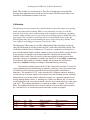
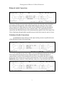
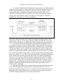
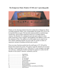
The Dangerous Music 2-Bus Manual
Thank you for choosing products from the exciting line of Dangerous Music
recording equipment. Many years of dependable and trouble-free
performance can be expected from our gear. This has been made possible by
careful design, construction, and top-shelf component choices by recording
industry veterans. This manual will assist the user with installation of the
2-Bus, as well as calibration of the system.
Contents
Introduction………………………………..
Safety review……………………………...
Overview and Hook up…………………...
Front Panel and Use……………………….
Calibration………………………………...
Grounding and Interface ………………….
Balanced and Unbalanced connections.......
Grounding revisited……………………….
Connector Pin-Outs………………...……..
Specifications……………………………..
1
2
3
4
5
6
7
8
10
11
Dangerous Music 2-Bus Manual
Safety Review
Certain precautions should be taken when using electrical products. Please observe the safety hints by
reading the manual and obtaining qualified help if necessary to adhere to the precautions. The power
supply must be switched to the proper mains voltage. PLEASE CHECK THE RED WINDOW ON
THE POWER SUPPLY TO VERIFY THE CORRECT SETTING FOR YOUR LOCATION
BEFORE CONNECTING THE MAINS PLUG!
1. Always use a properly grounded power supply cord with this product. Please do
not defeat the ground pin on the mains plug. This connection provides earth to the chassis and
signal grounds inside the device for clean and quiet operation. The “Grounding and interface”
section can help the user/installer clear up a buzz problem if one develops.
2. Avoid high temperature operation in equipment racks by providing air
circulation. The number one killer of electronic gear is HEAT. Vented rack panels may look like
wasted space to an interior decorator, but they look like beauty to a technician or equipment
designer! If the front panel is hot, it is roasting inside the box.
3. Avoid areas of high magnetic fields. The steel chassis of the Dangerous 2-Bus is
designed to shield the circuits from EMI and RFI (magnetic and radio interference). When
installing equipment in racks, it is prudent to put power amplifiers and large power supplies at
least several rack spaces, if not in a different rack, away from equipment that deals with low-level
signals. Separation of high level and low level equipment can pre-empt trouble caused by heat
and EMI.
4. Care should be taken to avoid liquid spills around equipment. If a spill occurs,
please shut off the gear and disconnect the mains. A qualified technician should investigate
accidents to prevent further equipment damage or personnel hazards caused by spills.
5. If one is uncomfortable with opening gear and changing jumpers or making
adjustments, please seek qualified help if necessary.
6. If adjustments or jumper changes are required, please disconnect the mains plug
before opening the top. Dropped screws or tools on a live circuit board can manifest themselves
as burn marks and smoked components. While we feel your pain, (been there) subsequent damage
is not covered by the warranty.
Dangerous Music Incorporated reserves the right to change the specifications or modify the designs
of its equipment. Sending in the registration card is our way of keeping in touch with users of our
equipment should this become necessary. Registration information is always kept confidential and never
disclosed to third parties for any reason. Company contact information is on the last page of this manual.
The CE sign on this product signifies the fact that the 2-Bus has been tested and
verified to conform to the applicable standards of 89/336/EEC. EN55103-1
(emissions) EN61000-2 (immunity) and EN60065:2002 (safety requirements)
2
Dangerous Music 2-Bus Manual
Overview
The 2-Bus is a 16x2 summing amplifier designed to help the users of digital audio
workstations achieve better mix performance through the use of cutting-edge analog
circuit design in conjunction with the existing equipment in their studios. The designers
and their colleagues have noted that while DAWs offer unprecedented flexibility in
multi-track recording and editing, the resulting mixes from these systems generally don’t
equal those of high-end analog recording systems in terms of sound quality, preservation
of spatial detail, headroom and ‘no latency’ ergonomics. In today’s portable environment
and with the cost of maintaining and housing legendary recording equipment, the choice
of a big desk is impractical for many users of DAW systems. We want to bring together
the best of both worlds. It is in this spirit that the Dangerous engineering team is
designing and manufacturing an exciting array of summing, mixing, monitoring,
metering, and mastering equipment to meet the needs of today’s recording engineers,
producers, and artists.
Hook up
The 2-Bus is designed to mix the outputs of up to 16 D/A converters to any stereo
recorder (16x2). The 2-Bus is easily stackable to increase channel numbers and system
functions when linked with other 2-Busses, Monitor, Monitor ST or 2-Bus LT. All of the
XLRs are pin 2 hot, and the connector groups are described as follows:
INPUT
The inputs are arranged into eight pairs of XLRs. They can be plugged
into directly from the D/A converters but system flexibility (and fun) goes way up with
the addition of a patch bay for ease of outboard equipment use.
OUTPUT
There are two stereo outputs on the 2-Bus. The Main output goes to the
mixdown recorder or A to D converter (or through mix buss compressors/EQs first, if
desired). The Monitor output is identical to the main and is intended to feed a monitor
controller (Dangerous Monitor or Monitor ST.).
REM/EXP The remote/expansion connector allows for expandability of the system.
The 2-Bus has a mix buss input on this connector to stack multiple 2-Buses or link with a
2-Bus LT. The pinout is on the Connector Pinouts page (p.10).
DC IN
There is a grey power cable to hook the 2-Bus to its power supply. It is
best to make sure that the power supply is off or unplugged when connecting the DC
power cable to prevent damage to contacts in the connectors.
3
Dangerous Music 2-Bus Manual
CHASSIS and GROUND The banana jacks are strapped together during assembly.
They are provided to accommodate grounding systems where the chassis and audio
ground need to be separate.
Front Panel and Use
There are three types of front panel controls on the 2-Bus.
+6dB gain switches boost the signal patched to any pair of inputs
MONO switches put the signals of a pair, normally panned hard left and right, up
the middle of a mix.
The Output Level Trim is a mix fine gain adjustment used to get the signal level
just right to the mixdown A/D converter, recorder (or EQ/Compressor if in the
chain).
The switches on the front panel are laid out so that the inputs can be treated as stereo
pairs (also known as “stems”) or as individual inputs panned up the middle of a mix. For
sounds that are panned somewhere in between the two extremes, a pair of D/A converters
is used, panning is done with your DAW’s software mixer and the Mono button is not
engaged.
For example, let’s say that one wants to mix a drum kit with bass, guitars, a lead
vocal, and reverb signals together. To keep things simple, let’s say that the engineer has a
DAW with 8 D/A channels available to patch to analog output processing if desired, and
then the 2-Bus. This mix has 8 tracks of drums, one bass, two guitars, one vocal, with
reverb and effects for maybe 2 dozen tracks total. Usually, a DAW user would mix this to
2 tracks and then bounce the result to a new pair of tracks, but by using 4 pairs of outputs,
audio flexibility can be improved by assigning the drums to DAW outputs 1 and 2, the
bass and vocal to 3 and 4, the guitars to 5 and 6, and finally, the effects returns to 7 and 8.
The bass and vocal want their own channels, so they are assigned straight to mono or
direct outputs with no panning, and the MONO button on the 2-Bus is pressed to pan
them up the middle. Maybe the drums need gain so the other outputs can be run hot. The
Gain button for inputs 1 and 2 would take care of this. The 2-Bus Main Output is then
sent to an A/D converter that is recording back into the DAW (or an external device such
as an editing system, tape machine, or CD burner) using the Output Trim Level to set the
gain precisely. Since the tracks are spread among several busses in the computer, the
individual levels can be run much hotter ‘inside the box’ resulting in a mix that has better
clarity, detail, and punch. The use of outboard processing means that individual stems can
be made to slam without using ‘outboard loops’ in the DAW and suffering another A/D
conversion with the inherent time delay issues and another digital fader with its loss of
4
Dangerous Music 2-Bus Manual
detail. This example is a bare bones mix. The effect of setting up a system like this
becomes more apparent as more tracks need to be mixed. The 2-Bus and 2-Bus LT are
stackable to accommodate systems of any size.
Calibration
The following sections provide a more detailed look at some of the aspects of recording
studio setup and trouble-shooting. While it is not absolutely necessary to read this
material, we feel that a basic understanding of the principles of calibration, equipment
interface, and grounding issues can go a long way to helping engineers before the going
gets rough. If one encounters inconsistent levels or hum problems in the studio, the
following hints may help in understanding the issues and resolving the problems. These
issues apply to recording gear in general, not just the 2-Bus.
The Dangerous 2-Bus comes to you fully calibrated and ready to hook up. In order to
enjoy the full benefits of a 2-Bus system, the D/A’s used with it should be aligned. This
can be done with the aid of a Voltmeter or VU meter in a compressor or other piece of
gear on hand) and the digital oscillator found as a plug-in in most DAW systems. While it
is not necessary to align the system, better and more consistent mix results will be
obtained if this is done. There are two levels that most digital recording systems have
seemed to converge on depending on whether the situation is for recording or mastering.
The difference between the two worlds is whether the maximum electrical stress is
imposed by amplitude limiting (recording) or slew-rate limiting (mastering).
Professional recording systems in the US have historically used the VU meter for
system alignment and level monitoring, so naturally, with many years of precedent, there
are holdovers today from that system (derived from the telephone and broadcast
industries). The standard of ‘0VU’ comes from the Bell Telephone engineers needing a
convenient way to measure signal levels in phone lines and switching systems. 600 ohm
balanced lines were the norm and 1 milliwatt of energy was a pertinent amount of juice
moving through phone circuits. A ‘building out’ resistor was added to the VU meter to
avoid loading the audio circuit down and the reference level cranked back up so the meter
read ‘0VU’. The resulting standard level wound up at +4dBu, or roughly 1.23 volts AC
RMS. This standard has been with us for more than 60 years now the world over and is
the ‘reference level’ to which most professional audio systems are aligned.
Alignment Chart
U
U
U
U
Volts AC
9.76 v
6.16 v
1.23 v
VU
Tilt
Tilt
0 VU
dBu
+22
+18
+4dBu
dBfs (recording)
0 (full scale)
-4dBfs
-18dBfs
5
dBfs (mastering)
Tilt
0 (full scale)
-14dBfs
Dangerous Music 2-Bus Manual
A/D converters in a recording situation are usually set to have a +22dBu maximum input
level to achieve full scale. This allows for occasional loud hits to not clip the converter.
D/A’s for this system would typically be aligned to have unity gain with the A/D’s. This
is done by running a -18dBfs signal at 1 kHz with the digital oscillator to the individual
D/A outputs one channel at a time. Turn the 2-Bus output gain knob all the way up and
measure the voltage across pins 2 and 3 of the 2-Bus output connector. If there is a device
in the studio that has a calibrated VU meter (Dangerous MQ, tape machine, compressor)
patching the 2-Bus into it makes for convenient adjustment. Set the D/A converter gain
so that the volume indicator reads 0 VU or 1.23 volts AC on the voltmeter.
After the D/A’s are aligned, the A/D’s are aligned by using the oscillator and one
of the D/A’s as a source. Feed that signal into the A/D’s one at a time and meter it in the
DAW. Adjust the A/D for -18dB full scale. Once all the converters are aligned, the
system becomes easier to handle because there is a wonderful consistency from channel
to channel. This makes cross patching and bussing assignment seamless.
Mastering systems are typically calibrated at -14dB from full scale for a
maximum analog signal level of +18dBu. The reason for this is because mastered signals
tend to be compressed and bright. There is a lot of rapid change (slew-rate) in the signal
that overloads processing gear and converters before the amplitude gets up to +22dBu.
Some savvy 2-Bus users set their D/A converters as if they were mastering to be
able to take full advantage of the dynamic range such a calibrated system has to offer. In
other words, A/D’s are set to avoid clipping for recording and D/A’s are set to avoid
overloading the mixdown converter. This is done by aligning one D/A at -18dBfs and
using it to calibrate the A/D’s as above. Then set the all the D/A’s so that -14dB full scale
is 0VU by running the digital oscillator at -14dB and adjusting the D/A output levels to
read 1.23 volts AC or 0VU. This allows one to run the stems at hot levels without
overloading the mixdown A/D converter.
Grounding and Interface
In order to achieve maximum performance of any recording system, the cables need to be
wired properly. Following are diagrams of frequently encountered wiring scenarios to
help explain some of the possibilities. We’ll start with professional, balanced, +4dBu
levels encountered in most studio systems and then cover some contingencies that happen
when interfacing -10dBV, unbalanced systems. Understanding this next bit is the key to
quiet, reliable, and consistent studio operation.
The balanced world is the easiest to deal with because the audio signals and the
shield are kept separate down the interconnect cables. Properly wired systems with
balanced interfaces can achieve impressive signal to noise ratios with the least amount of
bother. Unbalanced equipment (RCA connectors or _” connectors with tip/sleeve) can be
made to perform well but can be more bother because the signal reference voltage (the
low side or ground) and the cable shield are one and the same, unbalanced connections
having only 2 conductors in the cable. This sharing of signal and ground can cause
trouble because stray ground currents become the reference for the audio signal. This
situation can manifest itself as hum or buzzing sounds coming from the speakers and can
be remedied with some tinkering and jumper placement. The 2-Bus is designed to make
both types of connections easy and painless if some simple suggestions are followed.
6
Dangerous Music 2-Bus Manual
Balanced Audio Connections
The beauty of balanced connections is that they promote the idea that current should be
prevented from flowing down cable shields while letting the audio pass. Pins 2 and 3
carry a signal across them (transverse mode) and any interference that gets through the
shield is picked up equally by the wires (common mode). The common mode noise is
canceled by the differential action of the instrumentation amplifier in the first stage of the
2-Bus. Signal gets through and the grounds stay put inside their respective pieces of gear.
Unbalanced Audio Connections
An unbalanced source driving a 2-Bus input usually presents no problem because
of the differential action of the input stage.
It is a good idea to use 3 wire cables even in an unbalanced situation because the
2-Bus input can keep stray noise away from the signal even without the benefit of
common mode rejection. If an unbalanced source gives one trouble, then this is usually
because the source doesn’t have a proper ground reference. This is why there are Input
Shield Lift jumpers inside the 2-Bus (and many other pieces of professional audio gear).
7
Dangerous Music 2-Bus Manual
If a buzz is encountered, a quick test to see whether or not the jumper position should be
changed is to hold a wire (a piece of speaker cable with bare ends or guitar cable tips)
against a chassis screw of the source and the grounding post of the 2-Bus. If the buzz
goes away, then the 2-Bus top should come off and the jumper position should be
changed. We’ll repeat the appropriate cautionary notes from page two here:
5. If one is uncomfortable with opening gear and changing jumpers or making
adjustments, please seek qualified help if necessary.
6. If adjustments or jumper changes are required, please disconnect the mains plug
before opening the top. Dropped screws or tools on a live circuit board can manifest themselves
as burn marks and smoked components. While we feel your pain, (been there) subsequent damage
is not covered by the warranty.
The jumpers are located on the main audio board where the input wires connect. The
inputs are labeled and in order so finding the correct jumper is easy. These tactics rarely
need to be performed but if they do, please work on a well-lit table or workbench. We
always clean off enough space to have plenty of room so as not to lose screws and tools.
Using a cloth or other pad underneath the equipment will prevent scratches and damage
both to the gear and to the table.
Next is a quick set of hints about where to look when trying to cure buzz troubles
in a recording studio. While the techniques are not meant to be taken as Gospel (some
techs might disagree with this treatise, so be it) these bits of knowledge were gleaned
from decades of experience in test equipment use, manual reading, facility design,
construction, trouble-shooting and being the chief of maintenance in some of the world’s
top studios, as well as problem solving in the home studios of rock stars and remote
recording/live sound situations. These hints have proven to work in many situations while
keeping systems safe and quiet.
Grounding Revisited
While the usual scenario in hooking up equipment is that one plugs in the cables and
starts to work, the more complicated a system, the more likely it is that something will
not work correctly as far as hum and noise performance is concerned. While some would
blame the equipment, this is the equivalent of blaming the eggs for a bad soufflé. Usually,
hum and noise problems (and jitter or clock troubles in digital interfaces) can be traced to
poor planning and implementation of the studio’s grounding situation. It is illuminating
to realize that the engineers of yore in the recording, broadcast, and communications
industries have been through these troubles and figured out the solutions. History can
teach us a lot about how to avoid ground loops and their associated problems. The
manuals of many test instrument and recording equipment manufacturers from the ‘50’s
to the 80’s had chapters on how to fix hum and noise problems, and it is from this wealth
of information that the writer draws ideas from for trouble free grounding schemes.
8
Dangerous Music 2-Bus Manual
To comply with international standards and wiring practices, recording equipment
manufacturers are required to connect all the shield pins of audio and data connectors to
the chassis grounds of their gear. Sometimes, this can cause noise problems in large
systems where pieces of equipment are spread out around a facility because two
‘grounds’ are never quite at the same potential. This can cause ground loops (hums or
buzzing) if the cable shields are allowed to connect two chassis that are at different
potentials due to location, circuit wiring, or induction.
If the audio cables between the racks connect the equipment grounds together via the
shields and the racks are at even slightly different potentials (on different circuits with
different loads, long distance, etc) the shields will try to equalize the potential difference.
Juice will flow down the shields and broadcast hum into the signal wires they
were supposed to protect or wind up imposed on the reference ground of the receiving
equipment. This situation manifests itself as the all too familiar buzz of a ‘ground loop’.
The intensity depends on many variables but can go from unnoticeable to raging. Some
people in desperation resort to using AC plug “ground lifts” to defeat the mains safety
grounds in a random fashion until the system quiets down a bit. This in our view (and the
view of the safety standards organizations) is an unacceptable method of taming ground
buzzes. The simpler way is to make sure that all the gear has a good mains ground and to
lift the shields on the receiving ends of the audio cables. The principals at Dangerous
Music have wired up large, world-class facilities using this scheme and have brought
room after room online with no buzz problems from the moment of power up. This is
why many gear manufacturers have shield lift jumpers inside their equipment. If a noise
problem crops up, changing the jumper position will almost always cure the problem.
Planning out the wiring system to minimize the formation of ground loops solves
problems before they happen.
Many powered speakers seem to get their audio reference ground from the input
cable. This means that these shields should not be lifted at the XLR. One favored
technique for trouble shooting buzz issues is to make a short XLR cable with the shield
lifted on the Male connector and use this to test whether or not an interface warrants a
shield lift wiring permanently into its receiving end connector.
9
Dangerous Music 2-Bus Manual
Sometimes problems that sound like ground loops are caused by other situations. These
require trouble shooting beyond the scope of this section and a qualified technician may
have to make a visit if help is needed.
Expansion Inputs and Connector Pin-Outs
The 2-Bus has an expansion input port that allows connecting other 2-Buses and 2-Bus
LT’s, to increase the system size and capability. The 25-way ‘D’ connector on the rear
panel labeled REM/EXP is used for this purpose. The REM/EXP port is wired according
to the following chart. A pre wired expansion adapter for the 2-Bus is available when
multiple units are bought or additional units are ordered for a facility already using one.
Pin#
10
23
11
24
12
25
function
right +
right –
right shield
left +
left –
left shield
All the XLR connectors are pin 2 hot.
Pin 1 shield
Pin 2 + signal
Pin 3 - signal
So far, we have not seen Pin 1 hot (+), except after too many drinks…
The AC Mains cable
The mains cable uses a standard IEC connector. Please check the mains voltage
selector (the little red window next to the IEC connector on the power supply) to
make sure that it is correct for your location. The fuses for the voltage selection block
are _ ampere, fast blow AGC type. PLEASE DON’T PUT A FUSE OF LARGER
RATING IN THE BLOCK! Disconnect the mains cable before changing the voltage
or replacing a fuse. If a fuse blows repeatedly, this is a sign from Mother Nature that
something is wrong and the factory should be contacted for help at the link provided on
the Specifications page.
Please use pre-wired AC cables for this device unless a technically qualified person
makes the connections to a mains plug. In this case, use only high quality mains plugs
like Hubbel, Thomas & Betts, or similar. Remember, in America, Black is hot, White is
neutral, and Green is ground. In Europe, Brown is hot, Blue is Neutral, and Green with a
Yellow stripe is ground. It is critical to get this correct. Double check that it is!
10
Dangerous Music 2-Bus Manual
Specifications
Frequency response………………….
THD + Noise…………………………
IMD60 4:1…………………………...
Crosstalk Rejection………………….
Noise floor…………………………...
Maximum signal level………………..
Nominal operating level……………...
Input impedance……………………...
Output impedance…………………….
Gain accuracy………………………...
Power consumption……………….…..
Warranty…………………………….
1 Hz – 100 kHz within 0.1dB
0.0045% +4 dBu input level
0.0008% +22 dBu input level
0.0055% +4 dBu input level
0.0015% +22 dBu input level
>101dB @ 1 kHz
<-83 dBu audio band limited
+27dBu
+4dBu
12k ohms bridging
50 ohms
>0.02dB for any setting
25 watts
Free 2 year extended warranty with online registration.
Standard warranty: 90 days parts and labor, subject to
inspection. Does not include damage incurred through
abusive operation or modifications/attempted repair by
unauthorized technicians.
Dangerous Music, Inc.
USA
Europe
Dangerous Music, Inc.
231 Stevens Road
Edmeston, NY 13335
Dangerous Music, Inc.
Stieleichenweg 55
50999 Köln
Email: [email protected]
Tel: +49 2236 393731
E-mail: [email protected]
11