1
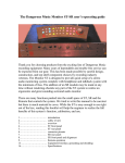
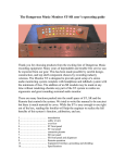
The Dangerous Monitor Manual
Thank you for choosing products from the exciting line of Dangerous
recording equipment. Many years of dependable and trouble free service can
be expected from our gear. This has been made possible by careful design,
construction, and top shelf component choices by recording industry
veterans. We are committed to providing equipment that brings you the
highest quality for your purchase.
This manual will assist you in the installation and use of the Monitor. There
are helpful hints for safety, grounding, and terminology that apply to all
recording equipment. Please take a few minutes to read the manual and
familiarize yourself with the outstanding features of your purchase.
Contents
Introduction ……………………….
Safety Review …………………….
Overview and hook up ……………
Usage Examples …………………..
Meter Wiring ……………………...
Balanced Audio Connections……...
Internal Jumpers …………………..
Equipment Interface……………….
Alignment …………………………
Specifications and Pinouts ………...
1
2
3
5
6
7
8
9
10
11
Safety Review
Certain precautions should be taken when using electrical products. Please observe the safety hints by
reading the manual and obtaining qualified help if necessary to adhere to the precautions. The power
supply must be switched to the proper mains voltage. Please check the red window on the power
supply’s IEC mains input module to verify the correct setting for your location before connecting the
mains plug.
1. Always use a properly grounded power supply cord with this product. Please do
not defeat the ground pin on the mains plug. This connection provides earth to the chassis and
signal grounds inside the device for clean and quiet operation. The “Grounding and interface”
section can help the user/installer clear up a buzz problem if one develops.
2. Avoid high temperature operation in equipment racks by providing air
circulation. The number one killer of electronic gear is HEAT. Vented rack panels may look like
wasted space to an interior decorator, but they look like beauty to a technician or equipment
designer! If the front panel is hot, it is roasting inside the box.
3. Avoid areas of high magnetic fields. The steel chassis of Monitor is designed to
shield the circuits from EMI and RFI (magnetic and radio interference). When installing
equipment in racks, it is prudent to put power amplifiers and large power supplies at least several
rack spaces, if not in a different rack, away from equipment that deals with low level signals.
Separation of high level and low level equipment can pre-empt trouble caused by heat and EMI.
4. Care should be taken to avoid liquid spills around equipment. If a spill occurs,
please shut off the gear and disconnect the mains. A qualified technician should investigate
accidents to prevent further equipment damage or personnel hazards caused by spills.
5. If one is uncomfortable with opening gear and changing jumpers or making
adjustments, please seek qualified help if necessary.
6. If adjustments or jumper changes are required, please disconnect the mains plug
before opening the top. Dropped screws or tools on a live circuit board can manifest themselves
as burn marks and smoked components. While we feel your pain, (been there) subsequent damage
is not covered by the warranty.
Dangerous Music Incorporated reserves the right to change the specifications or modify the designs
of its equipment. Sending in the registration card is our way of keeping in touch with users of our
equipment should this become necessary. Registration information is always kept confidential and never
disclosed to third parties for any reason. Company contact information is on the last page of this manual.
The CE sign on this product signifies the fact that the Monitor has been tested
and verified to conform to the applicable standards of 89/336/EEC. EN55103-1
(emissions) EN61000-2 (immunity) and EN60065:2002 (safety requirements)
-2-
Overview
The Monitor is designed to be the cornerstone of a recording studio by
providing a convenient method for listening to and metering the different
stages of the recording process. Careful attention to detail has resulted in a
unit of stunning ergonomic clarity and unprecedented performance in a
compact enclosure. The user will discover that the ability to select between
different analog and digital sources as implemented in Monitor allows
accurate assessment of program material without quality differences in the
signal paths clouding the user’s judgment.
The built in digital to analog converter provides a solid basis for comparing
digital sources directly without being subjected to the inevitable differences
in calibration and sound quality between the converters in separate pieces of
gear. Many times, the engineer can be fooled by differences in sound quality
of “clones” (DAT from a CD) because the different brands of equipment
don’t sound the same even though the data on the carriers is the same. The
topology of Monitor lets the engineer concentrate on the music and not the
process.
Hooking up your Dangerous Monitor
The connectors on the back of Monitor are arranged into 5 groups. The first
is the AES IN and THRU connectors. The user is to plug AES signals into
the female XLR connectors. Up to four devices are selectable for routing to
the built in D/A converter and digital meter feed. The XLR male connector
provide an uninterrupted through.
The second connector group is the “meter feeds” group. These jacks allow
the selected analog and digital sources to be sent to meters and/or phase
scopes to allow visual aid to the monitoring process. A breakout cable is
provided for the A-MTR feed.
-3-
The pinout of this connector is in the “Specifications” section of this booklet
and there is a circuit example for those who wish to set up a pair of VU
meters in the “Metering Circuits” section. The D-MTR jack feeds the
selected AES signal to a digital meter or phase scope.
The 3rd group of connectors is the ANALOG IN group. There are three
stereo inputs selectable by the switch group marked “ANALOG” on the
front panel. Note that the fourth switch selects the built in D/A converter.
Next are the OUPUT amplifier feeds. There is a MAIN and MINI set of
sends to drive power amplifiers. These feeds are balanced and low
impedance feeds capable of driving long cables.
The AC IN jack is where the power supply cable goes. It is best to make sure
that the power supply is turned off before connecting this cable to avoid
arcing the contacts. There are banana jacks provided for accommodating
different grounding schemes. The chassis and audio grounds are strapped
together at the factory. This works for most cases but the jacks are provided
for situations needing a different grounding scheme. If hum or buzz
problems are encountered, please consult the chapter on “Internal Jumpers”
for hints to clear up the situation.
The 25 way ‘D’ connector is to connect the Dim Command from a
Dangerous MQ and other expansion capabilities.
-4-
Usage Examples
The ANALOG switches select from four sources to be listened to. The
selected source is sent to the “Functions” group and the “A-MTR” feed on
the back panel. The fourth analog selection is a built in D/A converter which
is fed by the selected “Digital” switch.
The “Functions” group allows channel phase reversal, speaker mutes, mono,
volume dim, alternate speaker selection, and a VU meter offset (to keep
from thrashing the meter movements when listening to high level program
material). The volume control is a 21 position stepped attenuator. It was
decided in the design process to use an attenuator for its accuracy and
repeatability. It was also found that attenuators provide consistent sound
quality at all volume settings whereas pots tend to change sonic
characteristics and balance depending on the setting. Pots also require DC
blocking to reduce scratching noises on adjustment. The gain of most power
amps today is set very high so the attenuator range is set for about 30 dB of
loss. Since it is desirable to occasionally listen to the noise floor, which
requires unity gain at the volume control, the last two steps are pretty big.
Please use caution near the top of the volume control.
-5-
Meter wiring
The “A-MTR” feed is a buffered output designed to drive the VU meters and
headphone amp in the MQ metering and cue box. The feed can also drive a standard VU
meter circuit. The Monitor’s D/A is calibrated so that a digital sine wave of 1 kHz
frequency at -14dBfs will provide a +4dBu signal level. Calibration tones are available
from the oscillator in the DAW or a test CD.
Standard VU meter circuit
The selected Digital Input to be monitored is fed to the “D-MTR” XLR on the rear panel.
This output is a standard AES digital output that goes to MQ’s AES input or another
digital meter or phase scope.
Interface
The following section is intended to help installers set the system up for quiet,
dependable operation. If trouble is encountered setting up the Monitor, the suggestions
may help in understanding the issues and resolving the problems. The techniques
discussed while not infallible, have been used for many years by the engineers at
Dangerous Music with a fantastic success rate setting up dozens of world class facilities.
6-
Balanced Audio Connections
The beauty of balanced connections is that they promote the idea that current should be
prevented from flowing down cable shields while letting the audio pass. Pins 2 and 3
carry a signal across them (transverse mode) and any interference that gets through the
shield is picked up equally by the wires (common mode). The common mode noise is
canceled by the differential action of the instrumentation amplifiers in the first stage of
the Monitor. Signal gets through and the grounds stay put inside their respective pieces of
gear.
Unbalanced Audio Connections
An unbalanced source driving a Monitor input usually presents no problem
because of the differential action of the input stage.
It is a good idea to use 3 wire cables even in an unbalanced situation because the
Monitor input can keep stray noise away from the signal even without the benefit of
common mode rejection. If an unbalanced source gives one trouble, then this is usually
because the source doesn’t have a proper ground reference. This is why there are Input
Shield Lift jumpers inside the Monitor (and many other pieces of professional audio
gear).
The next section covers how to access the jumpers and how they work.
-7-
Internal Jumpers
Monitor is shipped from the factory with its internal jumpers set to interface with
balanced equipment. There are rare cases that certain gear may cause a buzz in the
speakers with the factory presets. The following sections have information that can help
the installer achieve quiet performance.
If one is uncomfortable with opening gear and changing jumpers or making
adjustments, please seek qualified help if necessary.
If adjustments or jumper changes are required, please disconnect the mains plug
before opening the top. Dropped screws or tools on a live circuit board can manifest themselves
as burn marks and smoked components. This type of damage is not covered by the warranty.
Input cable Shield Header Jumpers are on the main circuit board to facilitate proper
system shielding. If a speaker buzzing problem is encountered, the method to trouble
shoot this situation is to disconnect input wires until the buzz disappears. The cable
pulled when the problem cleared up tells one which shield header jumper should have its
position changed. The jumpers are clearly marked on the main circuit board.
If disconnecting all the inputs does not clear the trouble but disconnecting the amp feeds
does, then there is a ground loop or missing ground reference to the power amplifiers.
The following section on interface may give some clues as to how to solve these types of
problems.
-8-
Equipment Interface
The Difference between Grounds and Shields
While the usual scenario in hooking up equipment is that one plugs in the cables and
starts to work, the more complicated a system, the more likely it is that something will
not work correctly as far as hum and noise performance is concerned. While some would
blame the equipment, this is the equivalent of blaming the eggs for a bad soufflé. Usually,
hum and noise problems (and jitter or clock troubles in digital interfaces) can be traced to
poor planning and implementation of the studio’s grounding situation.
It is illuminating to realize that the engineers of yore in the recording, broadcast,
and communications industries have been through these troubles and figured out the
solutions. History can teach us a lot about how to avoid ground loops and their associated
problems. The manuals of many test instrument and recording equipment manufacturers
from the ‘50’s to the 80’s had chapters on how to fix hum and noise problems and it is
from this wealth of information that this writer draws ideas from for trouble free
grounding schemes.
To comply with international standards and wiring practices, recording equipment
manufacturers are required to connect all the shield pins of audio and data connectors to
the chassis grounds of their gear. Sometimes, this can cause noise problems in large
systems where pieces of equipment are spread out around a facility because two
‘grounds’ are never quite at the same potential. This can cause ground loops (hums or
buzzing in the speakers) if the cable shields are allowed to connect two chassis that are at
different potentials due to location, circuit wiring, or induction.
If the audio cables between the racks connect the equipment grounds together via
the shields and the racks are at even slightly different potentials (on different circuits with
different loads, long distance, etc) the shields will try to equalize the potential difference.
-9-
Juice will flow down the shields and broadcast hum into the signal wires they
were supposed to protect or wind up imposed on the reference ground of the receiving
equipment. This situation manifests itself as the all too familiar buzz of a ‘ground loop’.
The intensity depends on many variables but can go from unnoticeable to raging. Some
people in desperation resort to using AC plug “ground lifts” to defeat the mains safety
grounds in a random fashion until the system quiets down a bit. This in our view (and the
view of the safety standards organizations) is an unacceptable method of taming ground
buzzes. The simpler way is to make sure that all the gear has a good mains ground and to
lift the shields on the receiving ends of the audio cables. The principals at Dangerous
Music have wired up large, world class facilities using this scheme and have brought
room after room online with no buzz problems from the moment of power up. This is
why many gear manufacturers have shield lift jumpers inside their equipment. If a noise
problem crops up, changing the jumper position will almost always cure the problem.
Planning out the wiring system to minimize the formation of ground loops solves
problems before they happen.
Many powered speakers seem to get their audio reference ground from the input
cable. This means that these shields should not be lifted at the XLR. One favored
technique for trouble shooting buzz issues is to make a short XLR cable with the shield
lifted on the male connector and use this to test whether or not an XLR interface warrants
a shield lift.
Alignment
The Dangerous Music Monitor is carefully aligned at the factory. The alignment
procedure is provided here in case the user wants different levels on the D/A, Meter, or
Dim circuitry. Please don’t attempt to align this unit without proper laboratory equipment
and knowledge of its use. Refer to the main board diagram on page 8 for pot locations.
1. Set an analog oscillator to deliver +4dBu output and patch it to Analog Input 1.
2. Select Analog Input 1 and turn the speaker level control all the way up.
3. Meter the Main Speaker Output and note the level and press the Mono button.
4. Adjust P1 for the same level noted above. Release the Mono button.
5. Turn the oscillator up to +18dBu and press the Dim button.
6. Adjust P2 and P3 for 0dBu output. Release the Dim button.
7. Unplug the oscillator. Obtain a digital oscillator and set it to -14dBfs.
8. Feed the oscillator to Digital Input 1 and select Digital Input 1 and D/A.
9. Meter the Main output and adjust P8 and P9 to the levels measured in step 3.
10. Meter the A-MTR feed and adjust P4 and P5 for +4dBu output.
11. Push the -6VU button and adjust P6 and P7 -2dBu output.
To set other reference levels for the D/A converter, run the preferred digital level and
adjust P8 and P9 (along with the gain ranging jumpers H8 and H9) to read +4dBu at the
meter feed. Remember to have the -6VU button disengaged while aligning the converter.
(How many times have I forgotten that one, Doh!)
-10-
Specifications
Frequency response ……………………….. 1Hz – 100 kHz within 0.2dB
THD+Noise ……………………………….. 0.003%
IMD60 4:1 ………………………………… 0.002%
Interchannel crosstalk …………………….. -113dB
Dynamic range …………………………… 119dB
Maximum level …………………………… +27dBu
Nominal operating level …………………... +4dBu
Power consumption ……………………….. 50 watts
Warranty …………………………………... Free 2 year extended warranty with online registration.
Standard warranty: 90 days parts and labor, subject to inspection.
Does not include damage incurred through abusive operation or
modifications/attempted repair by unauthorized technicians.
Connector Pinouts
All of the 3 pin XLR’s are wired to the standard convention (one of several, really).
Pin 1
shield
Pin 2
+ signal
Pin 3
- signal
The “A-MTR” jack is a male 6 pin XLR. A breakout cable is provided with the unit
but one can roll one’s own with the following pinout.
Pin 1
Left shield
Pin 2
Left +
Pin 3
Left –
Pin 4
Right shield
Pin 5
Right +
Pin 6
Right –
Solder Pin 6 first when terminating the cable. The cup is easy to get to until the other wires get in the way.
The writer still occasionally makes that mistake.
The ‘D’-sub connector is used for access to the Dim function by the Dangerous MQ.
Pin#
function
1
Dim (for connection to MQ)
14
Relay common
USA
Europe
Dangerous Music, Inc.
231 Stevens Road
Edmeston, NY 13335
Dangerous Music, Inc.
Stieleichenweg 55
50999 Köln
Tel: +49 2236 393731
Email: [email protected]
E-mail: [email protected]
-11-