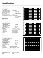
1
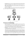
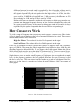
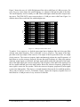
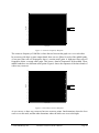
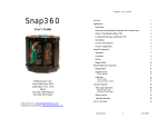
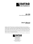
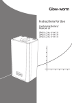
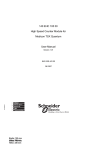
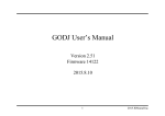
24CX-2
24CX-3
24CX-4
ELECTRONIC CROSSOVER
OWNER’S MANUAL
TDM DESIGN INC.
12800 NW BISHOP RD
HILLSBORO, OR 97124
PHONE: (503) 647-5957
FAX: (503) 647-5953
TDM-DESIGN.COM
IMPORTANT!
*** Read Before Using ***
CAUTION: The following must be observed to prevent
malfunctioning and/or possible equipment damage.
•Before plugging the unit into the main AC line, make
sure that all of the equipment following the crossover
output lines is turned off or all of the inputs are turned
down.
•Never change the frequency range switch from the x10
to x1 position (or vice versa) with the crossover output
levels passing signal. Transients can result and speaker
damage is possible.
•The unit should be plugged in only when it has been
established that the main AC line is supplying the correct voltage and frequency. US models are set up for
110 VAC at 60 Hz.
•Keep the unit away from excessive moisture.
•Allow only authorized technicians (consult your dealer)
to open the unit. TDM Design assumes no liability for
damage or injuries.
© 1996 TDM Design, Inc.
Electronic Crossover Owner’s Manual
Page 3
Table of Contents
INTRODUCTION................................................................................................................................................ 5
CROSSOVER FUNDAMENTALS............................................................................................................................... 5
CROSSOVER TERMINOLOGY ................................................................................................................................. 7
HOW CROSSOVERS WORK.................................................................................................................................... 8
MOUNTING THE UNIT IN A RACK...............................................................................................................11
USING THE SECURITY COVER ..............................................................................................................................11
HOOKING UP THE CROSSOVER ..................................................................................................................12
WHAT YOU’LL NEED..........................................................................................................................................12
MAKING ADAPTER CABLES.................................................................................................................................12
THE BASIC HOOK-UP..........................................................................................................................................13
TWO-WAY OPERATION (24CX-2 OR 24CX-4).....................................................................................................13
THREE-WAY OPERATION (24CX-2 OR 24CX-4)..................................................................................................14
THREE-WAY OPERATION (24CX-3) ....................................................................................................................14
FOUR-WAY OR FIVE-WAY OPERATION (24CX-4) ................................................................................................14
OPERATING THE CROSSOVER ....................................................................................................................15
FRONT PANEL CONTROLS ...................................................................................................................................15
ADJUSTING THE CROSSOVER FREQUENCIES .........................................................................................................16
CHECKING THE HOOKUP .....................................................................................................................................17
USING THE CD HORN BOOST ..............................................................................................................................17
ADJUSTING THE OUTPUT LEVELS ........................................................................................................................18
ADJUSTING THE INPUT LEVELS ...........................................................................................................................19
TDM OPTION CARDS ......................................................................................................................................20
OPTIONAL OUTPUT LIMITERS....................................................................................................................21
TROUBLESHOOTING AND SUPPORT..........................................................................................................22
NO SIGNAL OUTPUT ...........................................................................................................................................22
DISTORTION ......................................................................................................................................................22
EXCESSIVE NOISE...............................................................................................................................................23
60 HERTZ HUM OR BUZZ ....................................................................................................................................23
CONTACTING TDM............................................................................................................................................24
SPECIFICATIONS.............................................................................................................................................25
© 1996 TDM Design, Inc.
Electronic Crossover Owner’s Manual
Page 4
Introduction
T
hank you for purchasing the TDM 24CX series electronic crossover. These units are made
from the finest components and engineered to exacting standards. Precision components are
used in all critical circuitry for the finest sonic quality and performance. To get the most out of
your new crossover, please take a few minutes to review this manual and familiarize yourself with
the proper operation of the unit.
The remainder of this section provides background information about the theory of crossover
operation. Individuals that do not need this information may skip directly to the next section:
Mounting the Unit in a Rack.
Crossover Fundamentals
A crossover is used to divide a full-range sound signal into one or more frequency bands for
reproduction. This is necessary because most speaker components are designed to reproduce only
a portion of the audible frequency spectrum. A speaker system is made up of a collection of
speaker components, each of which can reproduce some part of the spectrum. The crossover’s
role is to divide the full-range sound source into the frequency bands appropriate to each of the
components in the speaker system.
Almost all sound reproducing systems have crossovers. In the majority of systems, including most
home and car stereo systems, and many commercial systems, the crossovers are in the speaker
cabinets. A speaker cabinet typically contains two or three, and sometimes even four or five different kinds of components. In some cases a single component is duplicated. For instance, some
cabinets have more than one low-frequency driver to increase low-frequency power-handling
ability and efficiency. The full-range power signal that is fed into a speaker cabinet goes through a
crossover that splits it into the different bands. The outputs of the crossover are connected to
each of the different speaker components to create a complete system. Figure 1 illustrates this
configuration.
© 1996 TDM Design, Inc.
Electronic Crossover Owner’s Manual
Page 5
Signal
Source
Power
Amplifier
Passive
Crossover
Low Transducer
Mid Transducer High Transducer
Figure 1 - Typical Passive Crossover Configuration
This kind of crossover is called a passive crossover because it does not use any power other than
the power contained in the signal to accomplish its task. Passive crossovers have certain limitations that make them inappropriate for large systems, or systems requiring high fidelity at high
sound pressure levels. Some of these limitations are…
• Insertion Loss: Some power is lost in the crossover network which lowers the efficiency
of the system.
• Power Handling: Passive crossovers that can handle more than a few hundred watts require very large, very costly components. This makes them impractical for high-power
systems.
• Fidelity: The nature of the way passive crossovers work makes it difficult to design them
with high fidelity in mind. The kinds of components used in passive crossovers tend to
color the sound in undesirable ways.
To get beyond these limitations, large systems, or medium sized systems that require high fidelity
incorporate active crossovers. TDM 24CX series crossovers are active crossovers. These crossovers are not usually housed in the speaker cabinet. They are separate units that are usually
mounted in a rack with the power amplifiers. They are called active crossovers because they
require power in addition to their input signal to carry out their task. Active crossovers are different from passive crossovers in many ways. Here are the key differences…
• Line Level Signals: Active crossovers work with the line level signal before it reaches the
power amplifier. This allows them to use smaller, better components and designs.
© 1996 TDM Design, Inc.
Electronic Crossover Owner’s Manual
Page 6
• External Power: Passive crossovers are simply inserted between the amp and the speaker
components. Active crossovers must be plugged into an electrical outlet in order to work.
• Higher Typical Rolloff Rates: Passive crossovers typically roll off at rates from 6 to 12
dB per octave. Most modern active crossovers have rates of at least 24 dB per octave
(more about rolloff rates later).
• More Power Amplifiers: Active crossovers break the signal into many different bands
before the power amplifiers. That means that you need one power amp channel per band.
Figure 2 shows a typical active crossover configuration.
Signal
Source
Active
Crossover
Lows Amp
Mids Amp
Highs Amp
Low Transducer
Mid Transducer
High Transducer
Figure 2 - Active Crossover Configuration
Crossover Terminology
• Crossover Frequency: This adjustment is often called the crossover point. It is the frequency where the sound crosses over from one speaker to another. For example, if your
low-to-mid crossover frequency is 125 Hz, then frequencies below 125 Hz are reproduced
by the low speaker and frequencies above 125 Hz are reproduced by the mid speaker. 125
Hz itself would be reproduced equally by both the low and the mid speakers.
• Rolloff Rate: A crossover’s rolloff rate determines how sharp the transition between one
set of speakers and another will be. Higher rolloff rates result in faster transitions. To better understand this concept, let’s take an example.
Suppose you have a crossover stage dividing your mid frequencies and your high frequencies. The crossover frequency of this stage is 2500 Hz. Sounds at 2500 Hz will be equally
reproduced by both the mid and high frequency speakers. As you go higher in frequency,
more of the sound is reproduced by the high speaker and less by the mid speaker. As you
go lower in frequency more of the sound is reproduced by the mid speaker and less by the
high speaker. If this crossover has a high rolloff rate (24 dB per octave), at 1250 Hz, the
© 1996 TDM Design, Inc.
Electronic Crossover Owner’s Manual
Page 7
difference between how much sound is reproduced by the mid speaker and how much is
reproduced by the high speaker will be 30 dB. In other words, at 1250 Hz, 30 dB more of
the signal is reproduced by the mid speaker than the high speaker. At 625 Hz, the difference would be 54 dB. With a low rolloff rate (12 dB per octave), the difference at 1250
Hz would only be 18 dB, and at 625 Hz it would be 30 dB.
Higher rolloff rates are generally considered good because they help protect speaker components from damage at frequencies that are too low for them to handle. They also result
in a greater overall efficiency of the system by making sure a band of frequencies is always
reproduced by the speaker components that are most efficient at reproducing it.
How Crossovers Work
To divide a range of frequencies into two or more smaller ranges, a crossover uses filter circuits.
A filter is simply a circuit that lowers the levels of unwanted frequencies in a signal. There are two
different kinds of filters used in crossovers:
• High Pass Filters: These reduce the levels of low frequencies in the signal.
• Low Pass Filters: These reduce the levels of high frequencies in the signal.
Filters roll off unwanted frequencies. Imagine that you have a high pass filter with a cutoff frequency of 1000 Hz. That means the filter is supposed to keep frequencies above 1000 Hz while
discarding frequencies below 1000 Hz. Do you suppose, then, that a signal fed into this filter at
999 Hz would simply not show up at the output? If you answered “No” you were correct! In fact,
a signal at 999 Hz would be virtually as loud at the output of this filter as a signal at 1000 Hz.
Signals that are above or near the cutoff frequency of a high-pass filter are reproduced at normal
levels. As the frequency gets lower, the level gradually decreases. The rate of decrease is called
the filter’s rolloff rate. This term comes from the fact that on a graph of a high-pass filter’s frequency vs. its gain, there is a smooth curve below the cutoff frequency. Here is an example of
such a graph:
5
0
-5
Gain (dB)
-10
-15
-20
-25
-30
-35
2300
2180
2060
1940
1820
1700
1580
1460
1340
1220
980
1100
860
740
620
500
380
260
20
140
-40
Frequency (Hz)
Figure 3 - Filter Frequency Response Curve
© 1996 TDM Design, Inc.
Electronic Crossover Owner’s Manual
Page 8
Figure 3 shows the curve of a 1000 Hz high-pass filter with a rolloff rate of 6 dB per octave. For
every for every octave below the cutoff frequency, we subtract 6 dB from the gain of the filter.
The cutoff frequency itself is actually at -6 dB. Filters with higher rolloff rates have steeper looking curves. The TDM 24CX series crossovers have a 24 dB per octave rolloff rate. Figure 4 is
what the above filter would look like with this higher rate.
5
0
-5
-10
Gain (dB)
-15
-20
-25
-30
-35
-40
2780
2660
2540
2420
2300
2180
2060
1940
1820
1700
1580
1460
1340
1220
980
1100
860
740
620
500
380
-45
Frequency (Hz)
Figure 4 - 24 dB per Octave Filter Curve
To make a 2-way crossover, we feed the same signal into a high-pass filter and a low-pass filter
with the same cutoff frequency. This is called the crossover frequency. The output of the highpass filter is the high output of the crossover. The output of the low-pass filter is the low output
of the crossover. The crossover frequency knob simultaneously adjusts the cutoff frequencies of
both filters to vary the crossover frequency. Because the cutoff frequency of a filter is the point at
which the output signal is 6 dB below the input signal (which means that it has half of the amplitude of the input signal), the crossover frequency is the frequency where half of the signal goes to
the low speaker and half goes to the high speaker. Below the crossover frequency, progressively
more signal is sent to the low speaker. Above the crossover frequency, progressively more signal
is sent to the high speaker. Thus, there is a smooth transition between the low and high speakers.
This is why we call it a crossover. To illustrate, Figure 5 shows the frequency response curves of
both filters in a 24 dB per octave 2-way crossover at 1000 Hz.
© 1996 TDM Design, Inc.
Electronic Crossover Owner’s Manual
Page 9
20
0
-20
Gain (dB)
-40
Low Output
-60
High Output
-80
-100
-120
-140
31
62
125
250
500
1000
2000
4000
8000
16000
Frequency (Hz)
Figure 5 - Crossover Frequency Response
The crossover frequency of 1000 Hz is where the two lines on this graph cross over each other.
In crossovers with three or more output bands, there are two filters for each of the middle bands.
A low-pass filter rolls off frequencies above a certain cutoff point. A high-pass filter rolls off
frequencies below a certain cutoff point. This leaves a band of frequencies in the middle. These
middle bands have two different cutoff points. Figure 6 shows the responses of the three bands of
a three-way crossover.
20
31
62
125
250
500
1000
2000
4000
8000
16000
0
-20
-40
Gain (dB)
-60
Low Output
Mid Output
High Output
-80
-100
-120
-140
-160
-180
Frequency (Hz)
Figure 6 - Three-Way Crossover Response
As you can see, a three-way crossover has two crossover points. One determines where the lows
cross over to the mids, and the other determines where the mids cross over to the highs.
© 1996 TDM Design, Inc.
Electronic Crossover Owner’s Manual
Page 10
Mounting the Unit in a Rack
T
DM 24CX series crossovers can be mounted in any standard 19” rack. Each TDM 24CX
series crossover takes up one rack space. To make mounting easier, lay the rack on its back
with the equipment front panels facing up. Remove any rack screws from the part of the rack
where you are planning to mount the crossover. Position the TDM 24CX series crossover in the
rack as desired. Make sure the mounting holes in the crossover line up with the screw holes in the
rack rails. Use four standard 10-32 rack screws for each crossover. We recommend that the rack
screws have plastic washers to prevent damage to the paint on the face of the crossover. Install
each screw loosely through a mounting hole in the crossover and into the rack. Do not tighten the
screws until they are all in place. After all four screws are installed loosely, make sure the crossover is placed exactly as you desire and then tighten the four screws until they are nice and snug,
but not overly tight.
Using the Security Cover
The security cover is used to prevent unwanted tweaking of the crossover settings. If your crossover will be installed permanently for one particular purpose, and will be set up once to operate
properly, use the security cover.
If you want to use the security cover on a 24CX-2 or a 24CX-4, make sure all of your settings are
correct, then install the cover. There are two holes in the face plate of the crossover— one on
either end. Position the cover so that its two screws line up with the two holes. Then, using an
Allen wrench, tighten the screws so that they are snug, but not overly tight.
The procedure is slightly different for the 24CX-3. This unit has buttons that protrude from its
face. To use the security cover, the buttons must be removed. You can do this by simply pulling
them off. They can be replaced at any time by pushing them back on. After the buttons have been
removed, unscrew the two Allen-head screws from the two ends of the face of the crossover
using an Allen wrench. Position the security cover over the face of the unit, insert the screws
through the holes in the security cover and into the holes in the face of the unit, and then tighten
the screws with an Allen wrench so they are snug, but not overly tight.
© 1996 TDM Design, Inc.
Electronic Crossover Owner’s Manual
Page 11
Hooking Up the Crossover
O
nce your TDM crossover is installed in the rack, you are ready to hook it up to your equipment. Of course, the method used to hook up any crossover depends on how it will be used.
We will try to give you the basics in this manual, but you may need to tailor the methods described here to your particular application.
What You’ll Need
To connect your 24CX series crossover to your equipment, you will need the following.
• Power: A power outlet should be located close enough to the unit so that you can plug it
in. The 24CX series crossovers require a grounded (3-prong) outlet. If an outlet is not
close enough, an extension cord or power strip may be used. Check the power rating on
the extension cord or power strip to make sure that it exceeds the power requirements of
all units plugged into it combined. TDM units have their power requirements marked on
the rear of the unit.
• Signal Cables: You need one cable to connect your signal source to the input of each
crossover channel that you will be using, and one cable to connect each crossover band
output from the channel to your amplifier input. TDM 24CX series crossovers have many
possible configurations. For example, if you are connecting a 24CX-2 for stereo 2-way
use, you need two cables to feed your stereo signal source into the two channel inputs,
and two cables for each channel (for a total of four) to feed the low and high outputs to
your amplifiers.
Making Adapter Cables
In order to hook up your crossover to the rest of your equipment, it may be necessary to use
special adapter cables. 24CX series crossovers can be shipped from the factory with either ¼”
phone jacks, or with XLR connectors. In either case, inputs and outputs are balanced. The ¼”
phone jacks are tip-ring-sleeve type for balancing. It is common to need adapters to go from ¼”
to XLR or vice versa. It is very important that if you build your own adapters, you adhere to
certain rules to make sure your TDM unit functions correctly.
If you have a TDM crossover with XLR connectors and you need to connect it to some other
piece of equipment that has ¼” connectors, you might need to build XLR to ¼” adapters. If the
other piece of equipment is balanced with tip-ring-sleeve jacks, then do the following.
• Wire pin 1 of the XLR connector to the sleeve of the tip-ring-sleeve plug.
• Wire pin 2 of the XLR connector to the tip of the tip-ring-sleeve plug.
• Wire pin 3 of the XLR connector to the ring of the tip-ring-sleeve plug.
© 1996 TDM Design, Inc.
Electronic Crossover Owner’s Manual
Page 12
If the other piece of equipment is not balanced, but has plain ¼” connectors, then do the following.
• Wire pins 1 and 3 both to the sleeve of the ¼” phone plug.
• Wire pin 2 to the tip of the phone plug.
It is very important that both pins 1 and 3 are wired to the sleeve. Some adapters leave pin 3
floating, and with TDM crossover units this will cause problems.
If you have a TDM 24CX series crossover with ¼” connectors, you may connect directly to other
equipment using ¼” connectors whether the other equipment is balanced or not. If you wish to
connect a TDM 24CX series crossover with ¼” connectors to another piece of equipment that
has XLR connectors, and you are making the adapters yourself, use tip-ring-sleeve type ¼” phone
plugs, and wire them this way.
• Wire pin 1 of the XLR connector to the sleeve of the tip-ring-sleeve plug.
• Wire pin 2 of the XLR connector to the tip of the tip-ring-sleeve plug.
• Wire pin 3 of the XLR connector to the ring of the tip-ring-sleeve plug.
The Basic Hook-Up
Begin by connecting the unit to a power source. Turn the power switch off. The power switch is
located near the power cord at the rear of the unit. It is off when it is in the “out” position. Pressing the switch toggles it between off and on states. Next, plug the power cord that emerges from
the back of the unit into an electrical outlet capable of supplying the correct voltage, current, and
frequency. This information is printed on the rear panel of your TDM 24CX series crossover.
Leave the unit turned off until all connections are made and you are ready to operate the unit.
The normal way to connect a crossover is between your sound signal source and your amplifiers.
For each channel, the output of the signal source that would ordinarily feed the amplifier is fed
into the crossover instead. The crossover outputs for each band are then fed into separate amplifiers and each amplifier drives a different set of speaker components (subs, mid-frequency drivers,
horns, etc.)
Two-Way Operation (24CX-2 or 24CX-4)
The 24CX-2 provides two channels for two-way operation. The 24CX-4 provides four channels
for two-way operation. The hookup procedure is the same regardless of which channel you use.
Feed a line level signal source (from your mixer, equalizer, or whatever) into the input of the
channel. Connect the low output of the channel to the input of your low amplifier. If desired, one
or more “Y” cables may be used to connect this output to the inputs of several amplifiers. Connect the high output of the channel to the input of your high amplifier. Again, more than one
amplifier may be used if desired.
© 1996 TDM Design, Inc.
Electronic Crossover Owner’s Manual
Page 13
Three-Way Operation (24CX-2 or 24CX-4)
The 24CX-2 provides one channel for Three-way operation. The 24CX-4 provides two channels
for three-way operation. In the 24CX-2 the two channels are combined to make a single threeway channel. In the 24CX-4, channels one and two are combined to make one three way channel,
and channels three and four are combined to make another three-way channel. The hookup procedure is the same for either unit. Press the channel link switch between the two-way channels to
link them together and form one three-way channel. This switch may be found on the rear of the
unit between the channels. It is recessed into the chassis through a small, square hole, and you
might need to use a small screwdriver to press it. When it is in the in position, the channels are
linked. When it is in the out position, the channels are not linked. Connect the output of your
signal source to the input of channel one (or channel three if your are using channels three and
four of the 24CX-4). Connect the high output of channel one (or three) to the input of your high
frequency amplifier. If desired, one or more “Y” cables may be used to connect this output to the
inputs of several amplifiers. The low output of channel one (or three) is not used. Connect the
high output of channel two (or channel four if your are using the second half of the 24CX-4) to
the input of your mids amplifier. Connect the low output of channel two (or four) to the input of
your lows amplifier.
Three-Way Operation (24CX-3)
The 24CX-3 provides two three-way channels. The hookup procedure is the same for either
channel. Connect the output of your signal source to the input of the channel. Connect the low
output of the channel to the input of your low-frequency amplifier. Connect the mid output of the
channel to the input of your mid-frequency amplifier. Connect the high output of the channel to
the input of your high-frequency amplifier. If you want, you can use a “Y” cable to connect the
output of a channel to the inputs of several amplifiers. Never connect more than one output to the
same input using a “Y” cable.
Four-Way or Five-Way Operation (24CX-4)
The 24CX-4 provides a single channel of four-way or five-way operation. Setting the unit up for
four-way or five-way operation involves removing the cover of the unit and switching an internal
jumper. For more information, contact your dealer, or call TDM (see Contacting TDM).
© 1996 TDM Design, Inc.
Electronic Crossover Owner’s Manual
Page 14
Operating the Crossover
O
nce you have mounted your TDM 24CX series crossover in a rack and connected all of the
cables, the unit is ready for operation. At this time, make sure the input levels on the front of
the crossover and the input levels of the amplifiers are all the way down. Next, turn all equipment
on. It is always best to turn the equipment on in the order of the signal path from input to output
and to turn it off in exactly the reverse order. For example, in a live sound reinforcement setup,
you might turn on the mixer first, followed by the signal processing equipment, then the crossover, and finally the amplifiers.
It is not absolutely critical that you use this ordering, but it is absolutely critical that the power
amplifiers are the last to be turned on and the first to be turned off. If the power amps are on
when any of the other equipment is turned on or off, a loud pop through the speakers can result.
This pop can very easily damage speakers. This is especially true in multi-amped systems (using
active crossovers).
Front Panel Controls
At this time, familiarize yourself with the controls on the front panel of the unit. The 24CX-4 has
four channels while the 24CX-2 has only two. The 24CX-3 has two channels, each of which is set
up for dedicated 3-way operation. All channels are identical, so you only need to understand how
a single channel works. Here is a list of the controls for a single channel of the 24CX-2 or 24CX4.
• Input Level: This lets you adjust the overall level of the channel. By turning this level up
or down, you can adjust the volume of all speakers for a single channel simultaneously.
• Low Output: This lets you set the level of the low-frequency output of the channel.
• High Output: This lets you set the level of the high-frequency output of the channel.
• Crossover Frequency: This control lets you adjust the crossover frequency of the channel. For more information about crossover frequencies, see Crossover Terminology.
• Frequency Range Switch: This switch selects the range of frequencies for the channel.
When this switch is in the out position, the frequencies indicated on the front panel of the
unit apply. When this switch is in the in position, the frequencies are multiplied by ten.
That means if you set the crossover frequency to 200 Hz, and then press the frequency
range switch in, the real crossover frequency for the channel is 2000 Hz. Never press this
switch unless the amplifiers are off or their inputs are all the way down. If the amplifiers
are on and passing signal when you change this setting, the resulting “pop” through the
speakers will be very loud, and can easily damage your speakers.
When the unit is set up for three-way operation (channel link switches in), the front panel controls
have different meanings. With the 24CX-2, channels one and two combine to make a single threeway channel. With the 24CX-4, channels one and two combine to make one three-way channel,
and channels three and four combine to make a second three-way channel. Figure 7 shows the
meanings of the front panel controls in this mode.
© 1996 TDM Design, Inc.
Electronic Crossover Owner’s Manual
Page 15
Control
Meaning for Three-Way Operation
Channel One (or Three) Input Level
Input Level
Channel One (or Three) Crossover Frequency
High-To-Mid Crossover Frequency
Channel One (or Three) Range Switch
High-To-Mid Range
Channel One (or Three) High Output Level
High Output Level
Channel One (or Three) Low Output Level
Not Used
Channel Two (or Four) Input Level
Not Used
Channel Two (or Four) Crossover Frequency
Mid-To-Low Crossover Frequency
Channel Two (or Four) Range Switch
Mid-To-Low Range
Channel Two (or Four) High Output Level
Mid Output Level
Channel Two (or Four) Low Output Level
Low Output Level
Figure 7 - Three-Way Control Meanings
Here is a list of the controls for a single channel of the 24CX-3.
• Input Level: This lets you adjust the overall level of the channel. By turning this level up
or down, you can adjust the volume of all speakers for a single channel simultaneously.
• Input Mute: Pressing this button mutes the input to the channel.
• Low Output Level: This lets you set the low-frequency output of the channel.
• Low Output Mute: This button mutes the low output of the channel.
• Mid Output Level: This lets you set the mid-frequency output of the channel.
• Mid Output Phase: Pressing this button reverses the phase of the mid output.
• Mid Output Mute: This button mutes the mid output of the channel.
• High Output Level: This lets you set the high-frequency output of the channel.
• High Output Phase: Pressing this button reverses the phase of the high output.
• High Output Mute: This button mutes the high output of the channel.
• Low/Mid Crossover Frequency: This lets you set the crossover frequency for the lowto-mid crossover point.
• Mid/High Crossover Frequency: This lets you set the crossover frequency for the midto-high crossover point.
Adjusting the Crossover Frequencies
With the amplifiers off or turned all the way down, set the crossover frequencies. Usually speaker
manufacturers recommend suitable crossover points for their products. It is very important that
the correct crossover frequencies are set before the system is used because improper crossover
frequency settings can damage speaker components even at very low sound levels. If your unit has
© 1996 TDM Design, Inc.
Electronic Crossover Owner’s Manual
Page 16
range switches (24CX-2 or 24CX-4), make sure they are in the correct positions for the desired
frequencies.
Checking the Hookup
It is critical that the crossover is connected and adjusted correctly before use. To avoid speaker
damage, we recommend checking your hookup and settings using the following method.
1. Make sure the input level and all output levels on the crossover are down. Adjust the
crossover frequencies according the recommendations of your speaker manufacturer.
2. Turn on the amplifiers and raise their gains about halfway up (leaving the levels on the
crossover all the way down).
3. Feed a program signal such as pre-recorded music into the system. At this point you
should hear nothing because the levels at the crossover are all the way down. Adjust the
signal level so you are feeding about -20 dBm into the system. If you don’t have meters to
verify this, just set the level a bit lower than normal.
4. Start with the highest frequency band for a channel. Raise the output level of that band up
about ¼ of the way.
5. Slowly raise the input level of the crossover until you just begin to hear the high frequencies.
6. Walk over to the speaker cabinets and put your ear right up to the high-frequency components (usually the horns) and verify that the high frequencies are coming out of these
components. This is to make sure you haven’t accidentally plugged the high frequency
output into the wrong amplifier input or hooked the high frequency speaker cable to the
wrong speaker input. If you have more than one high frequency speaker component on the
same channel, check them all. If something is not hooked up right, stop and fix it before
continuing.
7. Once you are satisfied that the high frequencies are being reproduced by the correct components, raise the crossover output level a little bit and listen to the sound. If you are
inexperienced, it may take a little practice to get used to what the various frequency bands
usually sound like. Make sure that the crossover points are correct. For example, if you
forgot to press in the range switch, you will hear some lower frequencies that shouldn’t be
coming from the high frequency speakers. Correct any problems before continuing.
8. Go back to the crossover and turn the high frequency output all the way down. Bring up
the next lowest band until you can just hear it. Repeat steps 6 and 7 for each band from
highest to lowest.
Using the CD Horn Boost
If you are using constant directivity (CD) horn designs for your high frequency speakers, your
system may require a CD horn boost. Consult your speaker manufacturer to determine if this is
the case for your system. If you need a CD horn boost, press the CD horn boost switches in for
the channels on which you need the boost. These switches are found on the rear of the unit next
© 1996 TDM Design, Inc.
Electronic Crossover Owner’s Manual
Page 17
to the input connectors. They are recessed into the chassis so you may need a small screwdriver to
press them. Pressing the switch in applies the correct boost to the input near which it is located.
This should be done before setting the output levels.
Adjusting the Output Levels
Start with the input levels at 0 dB (unity gain). After the rest of the system has been dialed in
(amplifier gains and output levels), the input levels can be fine tuned.
Feed a lower-than-normal level signal from your signal source into the system. You want to make
sure that you set it up so you have room to spare. If you can get enough volume out of the system
when your input signal is at -10 dBm then you probably have enough gain, so use some program
material such as recorded music and adjust the level of the signal source so you are feeding a -10
dBm average signal. If you are using a mixing console, the output meters should be reading -10
dBm on most of the signal peaks, and a little higher on the highest peaks. If you have equalization
on the system, make sure it is set to completely flat, or bypassed altogether. This applies to the
main system equalizer as well as any equalizer that affects your signal source such as the channel
equalizer on a mixing console.
Turn the output levels on the crossover all the way down and then turn the power amplifier gains
all the way up. Start with the frequency band that you expect to require the most gain. If you
don’t know which one that is, begin with the middle band in a three-way system or the band with
the most mid frequencies in a two-way system (often this is the high band). Raise the level of this
band until its volume is as loud as you ever expect to need it. If you are inexperienced, it may take
some time to understand how much gain you need for a particular application, but it is often best
to have a little more than you need because you can always turn it down at the source if it is too
loud. If you cannot get enough volume with the output level all the way up, raise the input level
until you have enough. If you cannot get enough volume with the input level and the output level
both all the way up then you need bigger amplifiers.
Next, raise the levels of each of the other bands to match the level of the one you have already set
until you have them all set so the sound is even and natural. Once you have them all set, you may
need to go back and fine tune them a bit. If you are setting up a three-way system, set the mids
first, the highs next, and the lows last. As you are setting the output levels of the crossover, remember that you are mainly trying to get the overall levels of the various speaker components to
match. The system may require equalization to even out the frequencies after the crossover is set.
A common mistake in a three-way system is to set the highs and low outputs too high to compensate for some mid frequency that is too hot in the midrange speakers. Then when that frequency is
reduced with equalization, the sound is crispy, dry, and generally unintelligible.
© 1996 TDM Design, Inc.
Electronic Crossover Owner’s Manual
Page 18
Adjusting the Input Levels
After setting up the entire system, you may find that the overall gain isn’t quite right. In some
cases the level of the first speaker component was set a little to high, and after all of the others
were brought up to match, the overall level is too high. In live sound reinforcement situations, it is
often the case that an approximate level is set up, and then when the event begins and the room
fills up with people, or the PA has to start competing with the sound coming off the stage, there is
not enough gain in the system and it must be increased. Use the input levels on the crossover for
these situations.
© 1996 TDM Design, Inc.
Electronic Crossover Owner’s Manual
Page 19
TDM Option Cards
T
he TDM 24CX series crossovers have internal connectors for option cards. A variety of
different option cards is available from TDM. Plugging a card into the connector inserts the
circuitry on the card between a crossover section output and the output of the unit. The most
common card to use for this application is the high-pass filter card. This card is used on the lowfrequency section of the crossover to remove subsonic frequencies from the output. This helps
remove stage rumble and wind noise, and also helps prevent speaker damage. Another popular
option is the parametric equalizer card. Each card has two fully parametric equalizer bands that
can be inserted on any crossover output. The cards are installed internally, so once they are set up,
they are under the cover and their settings cannot easily be changed. This is an advantage in situations where you don’t want the settings changed, but it is an obvious disadvantage in cases where
the settings will change often. In these situations, an external filter or equalizer is recommended.
For information about all of the available option cards, contact your vendor or call TDM (see
Contacting TDM).
© 1996 TDM Design, Inc.
Electronic Crossover Owner’s Manual
Page 20
Optional Output Limiters
T
he TDM 24CX series crossovers can be ordered with output limiters. These let you set the
maximum level for each crossover output. Limiters are used to help protect speaker components and ears from damage by excessive levels. Levels above the preset threshold are reduced
automatically by the limiter circuit.
If your TDM 24CX series crossover has limiters installed, you will find a set of small, yellow,
“trimmer” knobs recessed into the bottom of the unit— one near each crossover output. Use a
small screwdriver to adjust these. The units are shipped from the factory with the trimmers set
fully counter-clockwise. In this position there is no limiting. As you turn the trimmers clockwise,
you lower the limiting threshold, thus reducing the maximum output signal for a given crossover
output.
Set up and adjust the crossover for normal operation, then set the limiter thresholds as the final
step. One easy, effective way to set the limiter thresholds is by using any audio signal. Increase the
level of this signal until it just passes the threshold. In other words, keep increasing the volume
until it is slightly louder than you would ever want it to be. Then reduce the limiter threshold by
turning the little yellow trimmers clockwise until the volume of the signal is reduced adequately.
For example, if you want to set the limiters so that your amplifiers are never driven into clipping,
set up an input signal and increase it in volume until the amps just begin to clip; then reduce the
limiter threshold for each output until that output’s amp channel is no longer clipping.
© 1996 TDM Design, Inc.
Electronic Crossover Owner’s Manual
Page 21
Troubleshooting and Support
T
his section details various problems that you might encounter when using your crossover, and
the possible causes and solutions. It also tells how to contact TDM when you need service or
support for your 24CX series crossover.
No Signal Output
If you are getting a signal from some of the frequency bands, but one or more of them is not
working, check the cables and hookups for the band(s) in question. Make sure the cable between
the crossover output and the amplifier input is connected correctly. Make sure the speakers are
connected to the amplifier correctly. If there is still no signal after all of this, try replacing each of
the cables one at a time with a cable that is known to be good. If you cannot find the problem,
contact your vendor, or call TDM for support and/or service (see Contacting TDM).
If you are getting no signal from any of the output bands, make sure that the unit is plugged in,
turned on, and that the power light on the front panel is illuminated. If the unit is plugged in and
turned on, but the power light does not come on, try plugging some other piece of equipment into
the same outlet to make sure it works. If it does work, but you still don’t get the power light with
the unit plugged in and turned on, check the fuse on the rear of the unit. WARNING: Make sure
the unit is unplugged from the power outlet before removing the fuse!
Check the signal source to make sure it is working correctly. If the signal source seems to be
working correctly, try plugging it into some sound reinforcement equipment that is known to
work (such as a monitor system). If you do this and there is still no signal, the problem is that the
signal source is not providing a signal. If you plug the source into some other sound reinforcement equipment and everything works correctly, then the signal source is fine.
If the signal source is not providing a signal to crossover, check the cabling between the source
and the crossover. Try substituting another cable that is known to be good. If this fails, it’s likely
that your signal source is malfunctioning, or that there is some problem with the way the individual components of the source are connected.
If the signal source is providing a signal to the crossover, but you are still getting no output signal,
check to make sure that the problem is not with the power amps, speakers, or cables. The most
common cause this kind of problem is either a bad cable, or an incorrect hookup. The best way to
trace down a bad cable is to replace each cable in turn with one that is know to be good and then
check if that fixed the problem. If you cannot find the problem, contact your vendor, or call TDM
for support and/or service (see Contacting TDM).
Distortion
To determine the cause of the distortion, try systematically removing each piece of signal processing equipment from the chain, one at a time. After a piece of equipment is removed from the
chain (by plugging the piece of equipment before it directly into the piece of equipment after it),
listen to the system and determine if the distortion is still present. When you remove a piece of
equipment and the distortion goes away, then it is likely that this particular piece of equipment is
© 1996 TDM Design, Inc.
Electronic Crossover Owner’s Manual
Page 22
the cause of the distortion. If none of the signal processing units in the chain is causing the distortion, then either it is present in the signal source, or there is a problem with your speaker system,
amplifiers, or crossover.
If you determine that the TDM 24CX series crossover is the cause of a distortion problem, make
sure that the unit is plugged into a proper power source. Read the back panel of the unit for the
correct supply voltage and frequency (US models are set up for 110 VAC at 60 Hz). Using a unit
designed for 220 volt operation with a 110 volt outlet can cause distortion.
One of the most common causes of distortion is improper gain staging. That means that some
piece of equipment is operating at much lower than unity gain (the signal coming out of it is a lot
lower than what is being fed in). Under these conditions, there is often some piece of equipment
that must provide a very hot signal output to compensate. This can cause distortion in the output
stages of this unit, or in input stages of the unit that it is driving.
If the unit is plugged into the correct power source, the signal feeding the unit is clean, your gain
staging is normal, and you are still getting distortion, contact your vendor, or call TDM for support and/or service (see Contacting TDM).
Excessive Noise
TDM 24CX series crossovers have an excellent signal to noise ratio. If you hear excessive noise
in your system, try to determine its origin systematically. Remove each piece of processing gear
from the signal chain one at a time until you hear the noise go away. If none of the signal processing units is the cause of the noise, then the noise is probably present in your signal source.
If you suspect that the TDM 24CX series crossover is the cause of your noise problem, make sure
the unit is plugged into the correct power source. Read the rear panel of the unit to determine the
correct voltage and frequency (US models are set up for 110 VAC at 60 Hz). Using a unit designed for 220 volt operation plugged into a 110 volt outlet can cause very noisy operation of the
unit.
Make sure your gain staging is correct. If some unit in your system is running at a very low gain,
or if your signal source is weak, you may be running some other unit at a very high gain to compensate. Some audio equipment produces excessive noise when running at gain levels higher than
unity.
If you check all of these possible causes and you still can’t resolve the problem, contact your
vendor, or call TDM for support and/or service (see Contacting TDM).
60 Hertz Hum or Buzz
60 Hertz hum or buzz in a system can be extremely difficult to track down because it is usually
not a problem with any one piece of equipment. It is usually caused by how the entire system is
connected and grounded.
To fix a hum or buzz in a system, suspect any piece of equipment that gets a ground connection
from more than one place. These problems are called “Ground Loops” and the technical explanation of why they cause problems is that there is actually a voltage difference between the two
different grounds. The problem is most often caused by a single piece of equipment grounded to
© 1996 TDM Design, Inc.
Electronic Crossover Owner’s Manual
Page 23
two different power sources that are located some distance apart. For example, a mixing console
is plugged into a grounded outlet at the back of an auditorium, and the power amplifiers are
plugged into a different outlet 100 feet away at the stage. The mixing console is connected by
shielded cable to the amplifiers and the shield is grounded. This causes both the mixer and the
amps to be individually grounded, and each gets another ground from the other through the
shielded cable.
A problem like this can be fixed in several different ways. The mixer ground could be lifted. This
is commonly done by plugging the mixer’s three-prong plug into a two-prong grounding adapter
(you can get these at any hardware store), and plugging that into the outlet. This effectively disconnects the mixer’s ground lead from the outlet so that the mixer is now grounded only to the
amplifiers. The ground could also be lifted at the amplifiers so that they are grounded only to the
mixer. If the cable connecting the mixer to the amplifiers is a balanced (3-wire) type, the ground
can be floated at either end of this cable by disconnecting the wire connected to pin 1 of the XLR
adapter at one end or the other (but not both). Sometimes, because of the particular setup, you
will have to try several of these options before finding one that works.
CAUTION: Check local codes and regulations for rules pertaining to electrical grounding. It may be illegal in some places to lift
the ground of a piece of equipment— especially if this piece of
equipment is installed publicly.
Another common cause of ground loops is direct input (or DI) boxes. These let you plug an
instrument such as a guitar or bass directly into a microphone input. The problem is that the
person playing the guitar or bass might be using an amplifier or some other signal processing
equipment on the stage that is plugged into a grounded outlet. This creates a ground loop between their setup and the grounded outlet that the mixing console is plugged into. Fortunately,
many DI boxes have a ground lift switch that you can use to break this ground loop. Because they
are so convenient, ground lifts on DI boxes are often the first option tried when a hum or buzz
surfaces.
If you suspect that there is a problem with your TDM 24CX series crossover that is causing a
hum or buzz, try removing the unit from the system and plugging its outputs directly into power
amplifiers with speakers attached. Make sure that the TDM 24CX series crossover is plugged into
the same electrical outlet as the amplifier. If the hum or buzz is still present, there might be a
problem with the unit. In this case, contact your vendor, or call TDM for support and/or service
(see Contacting TDM). If the hum or buzz is not still present, the problem is somewhere else in
the system, and is probably a ground loop.
Contacting TDM
If you have a problem with your TDM 24CX series crossover that you cannot solve using this
troubleshooting guide, contact the vendor where you purchased the unit. If you need further
assistance, you can call TDM at (503) 647-5957 during normal business hours (9 AM to 5:00 PM
Pacific time). Our FAX number is (503) 647-5953. Our email address is [email protected]
and our web site is tdm-design.com. Your satisfaction is our business, and we are happy to help
you get the most out of your TDM 24CX series crossover.
© 1996 TDM Design, Inc.
Electronic Crossover Owner’s Manual
Page 24
Specifications
Frequency Response
Low Frequency Output
High Frequency Output
Total Harmonic Distortion
RL > 2 kohms
Low Frequency Output
High Frequency Output
Maximum Output Level
RL > 2 kohms
+0-0.5 dB 10 Hz
+0-1.0 dB 20 kHz
CONSTANT-DIECTIVITY CORRECTION
20.000
10.000
<0.01% THD
<0.02% THD
0.0
-10.00
+21 dBu (6.2 volts)
@<.05% THD
Maximum Voltage Gain
6 dB
Constant-Directivity Correction +3 dB @ 3.5kHz
rising at 6dB/octave
to 22.5 kHz
24CX-2, 24CX-4
Frequency Range
x1
80 Hz to 920 Hz
x10
800 Hz to 9.2 kHz
Hum and Noise (20 Hz-20 kHz)
Av = 0 dB, fc = 800 Hz
Low Frequency Section
Output @ 0 dB
<-106 dBu
High Frequency Section
Output @ 0 dB
<-97 dBu
Signal-To-Noise Ratio
118 dB
Controls
Input Level
Continuously variable
Output Level
Low, High Cont. variable
CD Boost
Rear panel switch
Channel Link
Rear panel switch
Power
Rear panel switch,
Led indication
24CX-3
Frequency Range
Low-Mid
80 Hz to 920 Hz
Mid-High
800 Hz to 9.2 kHz
Hum and Noise (20 Hz-20 kHz)
Av = 0 dB, fc = 230, 2.3k Hz
Low Frequency Section
Output @ 0 dB
<-98 dBu
Mid Frequency Section
Output @ 0 dB
<-95 dBu
High Frequency Section
Output @ 0 dB
<-93 dBu
Signal-To-Noise Ratio
114 dB
Controls
Input Level
Continuously variable
Output Level
Low, Mid, High Cont. variable
Phase
Mid, High front panel switches
Mute
Input, Low, Mid, High switches
CD Boost
Rear panel switch
Power
Rear panel switch, Led indication
Dimensions (W x H x D)
Weight
TDM DESIGN INC.
19 in. x 1.75 in. x 8 in.
8 lbs.
-20.00
-30.00
-40.00
-50.00
-60.00
20
100
TDM DESIGN INC.
1k
10k
20k
10k
20k
THREE-WAY OPERATION
20.000
10.000
0.0
-10.00
-20.00
-30.00
-40.00
-50.00
-60.00
20
100
TDM DESIGN INC.
1k
THD vs. LEVEL
2
20.00
1
10.00
0.0
0.1
-10.0
-20.0
0.010
-30.0
-40.0
0.001
.0005
-50.0
-40.0
-30.0
-20.0
-10.0
0.0
10.00
-50.0
20.00
0 dBu = 0.775 v rms