1
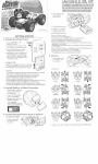
USER'S MANUAL
6" PLANER JOINTER
JOINTER SHOWN WITH
STEEL STAND AND ELECTRICAlS
SAFETY RULES FOR ALL POWER TOOLS
As With all electrical power tools it is important to read and follow the safety guidlenes in this
instruction manual. By using the tool in the in the manner for which it is designed and by follo
wing the safety precautions,it will considerably lessen the possibility
oF p ersonaf injury
BEFORE PLUGGING IN YOUR POWER TOOL
3 . Read the instruction manual fully and understand
the applications and potential safety hazards Do not
modify this tool without expert advice.
2. GROUND ALL TOOLS. If tooi is equipped with a
3 prong plug it shouid oniy be used with a 3 hole
recepticle. if an adaptor is used for 2 prong
recepticle, theadaptor lug must be attached to a
known ground.
00 NOT REMOVE THE 3R'D PRONG.
3. SAFETY GUARDS. are there for your protection,
ensure they are correctly fitted and in place.
4. ACCLDENTAL STARTING. Make sure switcn
is "OFF" before pivgging in your tool.
5. ADJVSTlFrSG KEYS Make sure all keys and tools
are clear ot work area.
6. KEEP WORK AREA CLEAN. Cluttered work area
sare 3 potential safery hazard.
7. WORKING APPAREL. Make sure you have n o
loose clothing such as tles. jeweiry that could get
caught.
DURING OPERATION
-
USE =ORRECT
Make sure you are
which it is
using the 'Oo' in the manner
designed.
2. FORCING YOUR TOOL. Do not force your tool it
wiil operate correctly and give better resuits using
normal pressure.
3.DON0 T OVERREACH. Keep a proper footing and
baiance a l all times,
4.T00L MAINTAtNANCE. A sharp and 'lean
wiil give you the best performance. Follow
instructions far lubricating.
5.CHANGING ACCESSORIES. Make sure machine
is switched "OFF" before chanoina
- - accessories and
make sure the accessories are desianed for vour
twl
in moving parts. An overall is recommended to be
worn during operation with sturdy rubber footwear.
8. SAFETY GOGGLES. use an approved safety
goggle or glasses to protect your ey8s.A dust mask
should alsobe used during dusty operations.
9. SECURE WORD. Firmly secure work piece in a
vice clamp or jig.Avoid getting your hands ciose to
moving parts.
10. WORK AREA Keep your surrounding work area
clean,dry and will illuminated.
11. KEEP CHLDREN AWAY. Before operation
ensure children or visitors are kept at a safe
distance.
t2. TOOL LOCATION Whether a floor or bench
model make sure your tool is on a leves surface
and cannot more during operation. Berch models
should be bolted down
AFTER USE
1. DISCONINECT YOUR MACHINE so tha
cleaning or rno
sdon.
2. CLEAN YOUR MACHINE and working arrea and
put all tools and accessories away out of the reach
Of Children'
3. DAMAGED
Before further use ensure
you replace faulty or damaged parts. Using your tool
without it being in perfect working order could proove
hazardous
4 , SERVICING keep your tool lubricated and clean
with all moving parts alligned and in good condlition
5. LOCK UP YOUR TOOL in an area where chiidren
or visitors can not gain access,
With Proper care and dmaintainance your power tool
can give you years of dependable service.
ADDITIONAL SAFETY RULES FOR JOINTERS
$.KEEP cutterhead sharp and free of all rust and
4. ALWAYS make sure exposed cutterhead behind
pitch.
2. ALWAYS use a push block when jointing stock
that does not give a reasonable distance of safety
for your hands.
3.NEVER pass hands directly over cutterhead.
thefence is guarded,especially when jointing near the
edge.
5. DO NOT perform jointing operations on material
shorter than 8 ioches. narrower than 314inch,or less
than 114inch thick
6. DO NOT periorm planing opmtions
sh&y
on materlal
than 8 i ~ h e g , n than
a ~ ~3/4imh,
~
wider
than 4 Inches.or thinner than 112 inch.
7. MAINTAIN the proper relationship of infeedand
wffeedAabre surfaces
knife pgth8- SUPPORT the work piece adequately at all times
during wration.maintain control of the work at all
times.
9. DO NOT back the work toward the infeed taus.
10. DO NOT attempt to perform an abnormal or little
used operation without study and the use of a d
e q u a t e h o Id - d o w nlp u s h biocks,jigs,
fixture.stops,etc.
11. DO NOT make cuts deeoer than 118" In a sinaie
pa,,, On cuts more than
" widedjust depth of cut
to 1116 or less to avold overtoaing machlne and to
minimize chance of kick back.
-
f4
-
UNPACKING AND C l fAMlNG
Carefully unpack the jointer, stand, and all loose
Items from the cartons. Remove the protective
coating from the machined surfaces of the
1oInter.This coating may be removed with a soft
cloth moktrmed with kerosene (do not use
acetone, gasoline or lacquer thinner for this
purpose). After
cleaning, cover
all
unpainted
surfaces with a good quality paste wax.
CHASSIS ASSEMBLY
1
I
_
FIX the chassis according to the chassis assembly
dtawing.(as shown in flgure two)
ELECTRICITY PART ASSEMBLY
Eleetrieaf machinery.switch and power source line
are all fixad-an the chassis.
First fix electrical machinery and power source
on the chassis, and then join eleetrlcal
machinery line to the switch line dots one and three
and join power source line to the switch line dots
line
two and four.Afierthat, fix the switch to the side
board.FIX erectricml machinery line and ground wire
of eleetrlcal source as shown @I fig.A(surfaees are
yellow and green) on the side board of the chassis,
using the screw and screw nut.(as shown in figures
Fig. 8
Aands) Fig.A
ASSEMBLING JOINTER TO STAND
1. When assembling the jointer to the stand, the
infwd and of the jointer is to be on the end of the
stand indicated as (1) Fig. C.The three holes (3) are
used for mounting the jointer to the stand.
2. Three hex head cap strews and lockwashers are
1
used to fasten the jointer to the stand. Place the
three lockwashers on the three holes (3) Fig. C. In
the stand and thread the screws In the three holes
in the base of the jointer.
Fig.
c
ASSEMBLING BELT ALlGNlNG PULLEYS AND
ADJUSTING BELT TENSION
Assemple the belt (3) to Ihe cutterhead pulley ane
motor pulley.(l),as shown in Fig. D. if necessary
loosen the nuts and bolts that fasten the motor to
the motor plate and move the motor up or down
on the motor plate until correct belt Zenslon
obtained. Correct tension is obtainedwhen there
approximately I" deflection in the center span
the belt using light finger puessure. Using
stralght edge,
align the
is
is
of
a
motor pulley to the
cutterhead pulley. if necessary both pulleys can
be moved in or out on the shafts or the complete
motor plate assembly can be moved In or out to
bring the pulleys into alignment,.
ASSEMBLING BELT AND PULLEY GUARD
The belt and pulley guard (1) is shipped with the
Fig.
D
w
stand. Simply assemble it to the stand uslng the
two screws and washers (2) as shown in Fig. E.
Fig. E.
ASSEMBLING CUTTERHEAD GUARD
Assemble the cutterhead guard assembiy
(1)Fig. F, to the jointer, by inserting the post (2)
of the guard assembly down through the hole in
the front table A spulng is supplled in the knob
assembly (31 Fig. F, that returns the guard over
the cutterhead aflter a cut has been made. To
provide spring tsnsion,turn the knob (3)fig F, to put
tension on the spring before inserting the post (2)
down through the hole rn the front table, make
sure the spring, enclosed m the knob (9,engages
the slot provided m the end of the post (2). If
spring tension Is toa much or not enough, remove
the guard and post and adjust spring tension
accordingly by rotating knob (3)
Fig. F
ELECTRICAL CONNECTIONS
1MPORfANT:Make sure the electrical characteristics are !he same between the
motor nameplate and the power source and make swe the power circuit the
Jointer will be used on Is properly fused. and that the wlre size b correct.
IN ALL CASES,MAKE SURE THE RECEPYACLE IN QUESTION IS PROPERLY
GROUNDED.
SINGLE PHASE INSTALLATION
If the motw on your machine is wired for 110
q
-V
single phase,the m e r cord Is equipped wlth a plug
that has two flat, parallel current
-
- tarrylnp
prongs
and one longer m n d w "W'
shaped, grolmd pr0.g
which requires a mating 3
conductw grounded
type receptacle as shown in Fig. G
110 VOLT
I
-
If the motor on your machine is wired for 220V
(240V)sirrgle phare.lfre Wwer cord is equipped with
a plug that has Iwa flat.current canylng prmqs In
-
tendem,and one round w "U" shaped longer ground
I240 VOLT)
GaPuHO
:
J
'
PRO*
-
-.
fip tt
i1
/ .I
prong.This is used only with the Draper mating 3
conductor grounding type receptacle, as shown In
rig. H w n n *e t n ~
- prong ooug on your
-
machine Is ~lvggedinlo a grounded 3
- conductor
receptacle, the lanp ground prong on the pllpg
contacts first so the machine is properly grounded
beford eiectricitv reaches it,
RAISING AND LOWERING TABLES
To raise or lower the front table. Imsen lock knob
(1)Fig J and turn handwheel (2) Fig. K.When table
is set at desired posltion.tlghten Lock knob (1) Fig
J.
To raise or lower the rear table ,Imsen Iwk Screw
(3)Fig. J,and turn handwheel (4) FEg. K.when table
Is
set at desired p o s i t i ~ , t i g h tload
~ screw (3) Flg.J.
REAR TABLE AND KNIFE ADJUSTMENT
For accurate owrk in most jointing operations, the rear table must be exactly
level with the knives at their highest point of revolution. This means, of course,
that the knives i n u ~ tbe parallel to the table and project equally from the
cutterhead.
To check this alignment proceed as follows:
1. Disconnect the jointer from the power
source.
2. Raise or lower the rear table as required,
by turning the rear table hand lever, until the
rear table is exactly level with the knives of
the
cutterhead at
their
highest point of
revolution.3.Place a straight edge on the rear
table, extending over the cutterhead as show
in Fig.L.
4. Rotate the cutterhead by hand. The biades
ashould just touch the straight edge.lf a knife
is too low or too hiqh
- at either end ,loosen
the lock screws in the knife slightly, shift the
AND HqW AUGWEHT
knife until it just touches thestraight edge,and
Fig. #.
tighten the screws securely.
After the rear table has been set at the correct height, it should not be
changed except for speclal operations and after sharpening knives.
I
If the rear table is too high-the result will be
as shown in Fig. M. The finished surface will
be curved.
REAR TABLE TOO MtGY
Fig. M
When the rear table i s too low. the condition woll be
as illustrated in Fig.N.The work will be gouged at the
end of the cut.
AS a final check of the rear table adjustment, run a
wood slowly over the knives for 6 to 8
piece of
inches; ~t should
rest
firmly on both tables, as shown in
F1g.0.wtth no open space under the finished cut.
Fig. 0
ADJUSTING TABLE GIBS
" Gibs" are provided to take up all pray between the
mating dovetail ways of the base and the front and
I
rear Zab!es of your jointer The "Gibs" are located
between the dovetailed ways of the front and rear
tables
and the
base. Proper
gib
adjustment
necessary for the correct luncliontng of the
is
jointer.
TheV'gibs"on your machine were adjusted at the factory
and should require no further adjustmeht, however,if it
ever becomes necessary to akjust the "gibs" proceed
as follows:
1. To adjust the outfeed table"gib",loosen all three gib
adjusting screws(7) Fig. P,and make sure the rear tabfe
lock screw(2)is loose.
2. Proceed to retighten the three gib adjusting screws
( ? ) starting
Fig.P
with the lowest screw first and as you
proceed toward the top,ralss up gently on the outboard
edge of the table being adjusted. This will offset any
tendency
of the table casting to "droop" or "sag" and
permit the glb to be brought up to a good secure fit.
The lnfeed table"glb"16 adiusted in the same manner
IMPORTANTDO not leave the screws too loose. it should take a little bit of effort to crank
the table up and down. Your jointer is a Finishing Machine and you can't expect to get a
very good jointer finish if the table is set loose and sloppy.
SEllING KNIVES
If the knives are removed from the head for
replacement or regrinding, care must be used in re
setting them as follows.
1. DISCONNECT
MACHINE FROM POWER
SOURCE.
2. Place a knife in its groove so that the rear edge
af the bevel is 1/15'' from the surface of the
cutterhead.
3. Slio lock - bar into place and tighten iodc screws
lightiy.
4. Place a knife setting bar made of a piece of
hardwood,approximately 12long jointed straight on one
edge,on the rear table,as shown in Fig.Q.
5. Rotate head backwards by hand and adjust blade
until 1 just touches the bar.
6. Using bar, heck blade at each end so that it is
parallet 20 'tabla top and tighten the screws.
7. Insert the other two knives and repeat adow
instructions.
-
Fig. Q
OPERATION
The following directions will give the beginner a start on jointer operaticn.tlse scrap pieces of
lumber to checd settings and to get the feel of the operations batore attempting regular work.
ALWAYS USE GUARD AND KEEPHANDS AWAY FROM CUTTERHEAD.
PLACEMENT OF HANDS DURING FEEDING
At the start of the eut,the ieft hand holds the work
firmly against the front table ane fence, whle the right
hand pushes the work toward the knives. After the cut
is under way,the new surface rests firmly on the rear
table as shown in Fig.R.The right hand puesses the
work fomrard and before the right hand reaches the
cutterhead it should be moved to the work an the rear
table. NEVER PASS NANDS DIRECTLY OVER THE
F9.R
CUTTERHEAD.
JOINTING AN
EDGE
This is the most common operation for the jointer. set the guide fence square with the table.
Depth of cut shouid be the minimum required to obtain a straight edge,Hold the best face of
the piece firmly against the fence throughout the feed.
JOINTING WARPED PIECES
If the wood to be jointed is dished or warpsd,take light cuts until the surface is tlat. Avoid
forcing such material down against the talble:excessive pressure will spring it while passing the
knives,and it will spring back and remain curved atfer the cut is completed.
JOINTING SHORT OR THIN WORK
When jointing short or thin pieces, use a push block to
eliminate all danger to the hands. Two types are shown
in Fig.S.They are easily made from scrap material.
Fig. S
7
One of the most useful jointer operations is cutting an edge to a taper. the method can be used on
a wide variety of work. Tapered legs of furniture are a common example.
Insread of laying the piece on the front table, lower the forward end ot the work onto the rear table.
Do this very carefully, as the piece will span the knives, and they will take a "bite" from the work
with a tendency to kick back unless the piece is firmly held. Now push the work forward as in ordinary
jointing. The effect is to plane off all the stock in front of the knives, to increese depth, leaving a
taperd surface.
The ridge left by the knives when starting the taper may be removed by taking a very light cut
according to the reqular method for jointing, with the front table raised to its usual position.
Practice is require in this operation, and the beginner is advised to make trial cuts on waste material
taper cuts over part of the length and a number of other spedal operations can easity be done by the
experienced crafsmna.
CUTTERMEAD MAINTENANCE AND REPAlRS
Aftw onslderable use.the knives will become dull and it wlll nut be possible to do accurate work.
Unless badly damqed by running into metal or other hard materlal,thw may be &wpm&
ss follows.
WHETTING KNIVES
DISCONNECT M E MACHINE FROM POWER SOUR=.
UB a fine carborundum stone,cova i t partly with pep=
.ss indicated in fig. V, to avoid mxklng the table.tay
the stone on the front table,lower the table and turn the
cutter head forward until the stone lles flat on the bevel
of the knif6.a~shawn.Hold the cutter head from turning.
and whet the bevelled edge of the knife, stroklng
lengthwise by sliding the stone back and forth across
the table.Do the same amount ot whetting on each d
the three blades.
BLADE CARE
LUBRICATION
Gum end pitch which collects on the blades causes
excessive frictlon as the work continues,resulting in
over heating the blades, less efficient cutting, and
consequently loss of blade life.Use"Gum and Rust
we suggest using a good grade of light grease on the
Remover" to wlpe this off the blades.
When these blades become dull enough so that it Is
noticeable when cutting,they should be resharpened.
A sharp blade works easier and results in longer
blade life.The penalty paid for a dull blade is less
steel adjusting screws for the raising and lowerinp
mechanisms of the front and rear work tables.
Occasionally apply a few drops of light mxhine ail to
the glbs on the right side of each work table so the
tables will slide freely in relation to the base casting.
The cutterhead runs in two single row sealed and
shielded ball bearings.which are pre tubrlcated for their
entire life.
-
blade iife and greater wear and tear on all parts of
the rnachlne.
In time rust may appear on the table and fence and
other parts of the jointer ,resulting In less emciency
and accuracy of the rnachine.Use paste wax which
can be applied to prevent rust formation,if however,
rust has aiteady formed on these parts use "Rust
Remover" which wlll restore the machine to its
original accuracy when applied.
CUTTERHEAD REPAIRS
Whem the knives of the cutterhead cannot be properly sharpened to produce a nice smooth,clean cut by
the methods desoribed above,they must be greund to a new bevel edge.ln this case,or when the beatlngs
of the cutterhead need replacement. remove the entire cutterhead with bearings and housing from the
housing from the base casting back out the hexagon head cap screw from each bearlng houslng which is
bstned to the machined curved seats of the base casting.
We suggest the customer purchase an additional cutterhead assembly complete with bearings and
housings.The extra cutterhead assembly is necessary to keep the machine In operation when the orlginal
cutterhead Is sen back to the factory for repairs, such as, replacement of bearlngs,grlndlng and resetting the
knlves.The addltlonal cost of an extra cutterhead assembly is lustifled when maxlrnum productban of hlgh
quality type work is repuired.
when mounting the cutterhead to the base casting of the jointer.be sure the machined curved seats of the
base casting are cleaned free from any dust,dirt,or greaw to obtain a good tight fit.
FENCE MOVEMENT
The modd GI182 fence has positive stops at 45'and W'to
allow quick return of the fence lo Ihese
positions after penormirig beveling merations at different angle settings. The 90" stop consists of an
adjustable bolt and tab that can be rotated out of the way when the fence angle 3s to be changed.An
overflew ofthe fence i s shown in Figwe X.below.
IMPORTANTDO NCT slide the fence acrcss the cutteed table.Scratchlng will result.
To change the fence angle:
1. Loasen the Lcck handle.
2. Turn the tab away from the 90" positive stop ball.
3. Tilt the fence te the desired angle and tighten the lock handle
To return the fence to 90'
1. Loosen the lock handle.
2. Return the fence to its uprlght position.
3. Fllp the stop tab back to its down position.
4.
Move the fence until the 90" positive
stop bolt touches the tab.
5. fighten the Imk handle. Over or under
- tightening the l o c k
lence. Check the angle of the fence with a high
-
handle wiil affect the final angle dins
quality machinist's or try square.Readjust ff necessary.
90° STOP ADJUSTMENT
Nate:The Mlwvlnp procedures ior the !@and
4S0 stops assume the outfeed table hss been
adlusted ~lrrectly.rfIt hss nd,refer to Sectton
X.C.befwe proceeding.
I. Place a square on the outfeed tabIe falrly
close o the cutterhead.See R Q WV.~
2. Rough adiustmenl can be made by loosening Ihe checknut on the degree tilting rod and turming the rod
itsell,lt may be necessary to insert a sman tori through the tilting rod fuf ktter lwerage.To adjust.loosen
the checknut on the positive stop bolt, then lurm the bolt against the tab until the fence conracts the
edge of the square evenly See Figure 14.
3. Tlghten the checknut on the stop boit and titt the fance 1orward.then back against the stop.
- check with the square.Tightening the checknut
- and- error may be necessary to perfect y w settings.
4. Re
45O
*ill move the stop bolt slightly, so some trial
STOP ADJVSTMEldT
be perpendicular to the outfeed !able.The fence can atso be tilted
away from the table by loosening the l0Ck handle.lifting UP the w p a s i t l v e rtop tab,and moving the fence in
Ihe desired dlr%ctlon.See Figwe 13 for adjustment Iocalims.To s H Ihe 4 p t a b stop:
1. Loosen checknut and lower fence untu It rests on the stop boll.
2.Using a bevel gauge set to 45',place the heel of the bevel on the d e e d tabte,and the blade against the
When the fence 18 properly aligned,lt wlll
fence.
3. If there is a gap between the bevel's Made and h e lace of the fence,turn the stop bolt until the gap is
me.
4. Tinten jamnul.Move your fence foward.then back against the atop.Re
- check the stop bolt
(J6A-$0) ASSEMBLY DIAGRAM
REF
01
02
03
04
05
06
07
08
PART#
J6A-1-07
J6A.l-09
J6A.f-08
J6A.1-10
DESCRIPTION
BASE
FRONT TABLE
REAR TABLE
GIB
LOCK SCREW
BOLT M6 x 25
NUT M6
J6A.1-13
TABLE ADJUST ROD
09
€-CLIP 19
10 J6A.1-12
LEAD SCREW BRACRET
11
FLAT WASHER
12
I
~
6
~
.
1
1
5
LEADSCREW
13
SET SCREW M6 x 8
1 4 J6A-3-25 BELTGUARD
FLAT WASHER 8
SCREW M8 x 12
WARNING LABEL
CUTTERHEAD GUARD
REF
1
19
20
1
DESCRIPTION
PART #
J6A.1-16
J6A.l-24
HAND WHEEL
RETAINER WASHER
SCREW M5 x 12
FLAT WASHER 6
24
25
-
29
. --
12
32
FENCE SUPPORT
HEX BOLT M I 0 x 30
J6A.3-01
30
31
J6A.3-02
,
FLAT WASHER 10
KEY
ROLL PIN 4 x 12mm
BOLT M6 x 12
BOLT M8 X 25
FLAT WASHER
CJ6A.2-01 STAND ASSEMBLY DIAGRAM
REF
PART#
J6A.2-01
J6A-2-02
-03 J6A.2-07
01
02
-
DESCRIPTION
ROOF
REINFORCE PLATE
URRlGHT
BOLT M8 x 25
NUT M8
WASHER 8
LOCK WASHER 8
RIGHT PROTECT PLATE
J6A.2-f 2
-
CABLE 1.8M
18
19
J6A-2-03
J6A-2-06
SWITCH 16A
PLASTICS CLIP
SCREW M4 x 16
NUT M4
SCREW M5 x 8
NUT M5
CEAR WASHER 5
FRONT SIDE PLATE
CROSSBEAM PLATE
REF PART #
20
21
22
23 J6A.2-05
24 J6A.2-13
25 J6A-2-16
26 J6A-2-10
27
28
29 J6A.2-14
30 J6A-2-09
31 J6A.2-11
32 J6A.2-08
33 J6A.2-15
34
35 J6A.2-04
36
-37 36A.2-I7
1
-
I
DESCRIPTION
SCREW M8 x 12
NUT MS
WASHER 8
SIDE LINK PLATE
CHASSIS SHIM
CHASSIS
RIGHT TAPPING FENDER
SCREW M8 x 12
SCREW M5 x 15
STOP BLOCK
LEFT TAPPING FENDER
LEFT PROTECT PLATE
TAPPING PLATE
BELT WHEEL
SET SCREW M6 x 8
BEHINDSIDEPLATE
MOTOR
UPPER LINK PL4TE
CUTTERHEAD
REF
I201
I
PART#
S6A.1-04
I
I
206
207
208
L
209
210
-1
21 3
214
J6A.1-02
J6A.1-03
J6A-1-01
21 5
216
15
I
DESCRIPTION
CUTTERHEAD
GI0 BOLT
HEX NUT M I 0
LOCK WASHER C$10
STUD
BEARING BLOCK
BEARING E6202
BEARING €6203
BEARING BLOCK
PULLEY
SETSCREW M6 X 8
KNIFE SETTING GAUGE
1
SWITCH ASSEMBLY DIAGRAM
[ REF 1 DESCRIPTION / QTY I
1 ;1 1 ;1
1
4
1
Nut M4
ScrewM4*15
Screw M4*25
10
Nut M5
1
1I