1
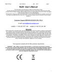
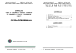
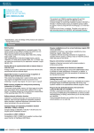
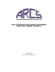
ARCS LIGHTNING MANUAL
HARDWARE AND SOFTWARE INSTALLATION,
VERSION 1.2
04 March 2001
http://www.arcsinc.com
c Copyright 2001
by Advanced Realtime Control Systems, Inc.
All Rights Reserved
ii
Contents
1 Introduction
1
2 Hardware and Software Overview
2.1 Hardware Overview . . . . . . . . . . . . . . . . . . . . . . . . .
2.2 System Requirements . . . . . . . . . . . . . . . . . . . . . . . .
1
1
2
3 Installation
3.1 Hardware Installation . . . . . . . . . . .
3.2 Software Installation . . . . . . . . . . . .
3.3 Changing the I/O Base Port . . . . . . .
3.4 TI Code Generation Tools . . . . . . . . .
3.5 Java-related Items . . . . . . . . . . . . .
3.6 Configuring for Multiple ARCS users . .
3.7 Home Directory Environment Variables .
.
.
.
.
.
.
.
.
.
.
.
.
.
.
.
.
.
.
.
.
.
.
.
.
.
.
.
.
.
.
.
.
.
.
.
4 Hardware Reference
4.1 Memory Configuration . . . . . . . . . . . . . . .
4.2 Digital-to-Analog Converters . . . . . . . . . . . .
4.3 Analog-to-Digital Converters . . . . . . . . . . . .
4.4 Encoder Counters . . . . . . . . . . . . . . . . . .
4.5 Discrete Input/Output . . . . . . . . . . . . . . .
4.6 I/O Connector . . . . . . . . . . . . . . . . . . . .
4.7 Extended Discrete I/O . . . . . . . . . . . . . . .
4.8 External Connections and Power Considerations
4.9 Expansion Bus . . . . . . . . . . . . . . . . . . . .
iii
.
.
.
.
.
.
.
.
.
.
.
.
.
.
.
.
.
.
.
.
.
.
.
.
.
.
.
.
.
.
.
.
.
.
.
.
.
.
.
.
.
.
.
.
.
.
.
.
.
.
.
.
.
.
.
.
.
.
.
.
.
.
.
.
.
.
.
.
.
.
.
.
.
.
.
.
.
.
.
.
.
.
.
.
.
.
.
.
.
.
.
.
.
.
.
.
.
.
.
.
.
.
.
.
.
.
.
.
.
.
.
.
.
.
.
.
.
.
.
5
5
9
17
19
19
21
21
.
.
.
.
.
.
.
.
.
22
23
23
24
25
25
25
27
28
29
ARCS Installation Manual
1
1 Introduction
This manual provides the installation instructions for the ARCS base product installation.
For a description of ARCS additional product offerings and extended features for control please refer to www.arcsinc.com .
If the platform upon which you are installing is Linux, please also consult
ARCS Installation Supplement for Linux for additional instructions and
notes specific to software installation on Linux.
2 Hardware and Software Overview
This section provides a very brief description of the hardware and software
components contained in ARCS base product installation. Together these
components comprise a complete control system. The section also provides
a summary of system requirements and recommendations.
For a more detailed overview of ARCS control system, please refer to ARCS
Integrated Development Environment (AIDE ) User’s Manual. This is helpful
reading, even if you do not plan to use AIDE.
2.1 Hardware Overview
The hardware -ARCS Lightning DSP Board -consists of a core computational capability using the Texas Instruments TMS320C31 (40 MHz), a
minimum of
128 32kW
of 0 wait state RAM, and PC ISA Bus communica-
tions. There are also a number of I/O components included on-board: 4 or
8 digital-to-analog converters, 4 or 8 optical encoders, 8 analog-to-digital
converters, and 32 bits of discrete input/output.
2
2
HARDWARE AND SOFTWARE OVERVIEW
Application code for the hardware can be written in C (recommended) or
TI C3x assembly. The code can then be downloaded to the hardware.
2.2 System Requirements
Currently, the following device drivers are available for the ARCS Lightning
DSP Board. For updates to the ARCS Lightning Driver list please consult
www.arcsinc.com
Windows NT 4.0 (Intel) Driver. If your hardware host is running Windows NT 4.0 operating system, then you need to install this device
driver on the hardware host.
Linux Driver. If your hardware host is running Linux operating system, then you need to install this device driver on the hardware host.
The hardware uses one ISA bus slot. There are no other requirements
imposed by the hardware.
For additional system requirements specific to Linux, please also consult
ARCS Installation Supplement for Linux .
ARCS control system is based principally on Java, TCP/IP networking protocol, and Java’s distributed computingmodel, Remote Method Invocation
(RMI).
ARCS software is based on Java. While the software should run on any
operating system that has a Java Virtual Machine (JVM), ARCS makes no
claims with respect to operating systems it has not explicitly tested on.
To date, ARCS software has been explicitly tested on the following JVM
supported operating systems: Win32 (e.g. 95, 98, NT), Linux, and Solaris.
For an up-to-date list, please consult www.arcsinc.com
ARCS Installation Manual
3
The ARCS System has been tested only with the Sun Microsystems, Java
1.1.8. Any other manufacturer’s compatible Java Virtual Machine should be
acceptable; however, no testing has been done and A.R.C.S., Inc. makes no
claims in this regard. This system also requires Sun Microsystems’s Swing
1.1.1.
The required swing 1.1.1 class file and the JRE 1.1.8 distribution are
included with the ARCS base product installation package per Sun Microsystems licensing terms. Information for alternative configurations is
provided later in this document.
As with any operating system performance, the faster the CPU and the
larger the memory, the better the overall system response time. If, for
example, your operating system is Windows NT 4.0, then a Pentium, 200
MHz with 32 MB RAM or similar is advisable.
Any computer that will participate in ARCS Remote mode distributed control should also have TCP/IP (the Internet network protocol) configured.
The win32 computer on which you will develop applications for the ARCS
Lightning DSP Board also requires the Texas Instruments Code Generation Tools to build applications.
The required disk space for the complete system on a Window NT platform,
for example, is provided in Table 1.
4
2
HARDWARE AND SOFTWARE OVERVIEW
T ABLE 1: Disk Space Requirements
Component
Manufacturer
Req’d Disk Space
ARCS Software
A.R.C.S., Inc.
< 10 MB
Java, choose one:
Java Runtime
Sun Microsystems
3.0 MB
Environment 1.1
Java Development
Sun Microsystems
26.5 MB
Kit 1.1
TMS320C3x/C4x Code
Texas Instruments
4.6/8.6 MB
Generation Tools V5.0/5.1
ARCS Installation Manual
5
3 Installation
3.1 Hardware Installation
This section describes how to install the ARCS Lightning DSP Board.
◆◆ Caution:
The ARCS Lightning DSP Board is sen-
sitive to electro-static discharge (ESD). Do take appropriate precautions:
Do hold the board by the edge.
Avoid direct contact with traces, components, and
connectors, including the edge connector.
Do not handle and store in a high ESD environment (carpeted and/or low humidity areas).
Use a grounding strap during handling.
The ARCS Lightning DSP Board will need to be installed in an available
ISA slot after the base address has been selected and set on the card. The
first order of business is to select an appropriate address for the card.
Windows NT Diagnostics from the Administrative Tools menu can be run
to identify I/O port locations which have been claimed and are unavailable.
Fig. 1 shows a typical Windows NT Diagnostics screen. In this particular
example, the ARCS driver (labeled arcs01x.sys) has already been installed.
◆◆ Caution: Some manufacturer’s drivers are not polite about publishing their claim on the I/O space. If after installation the ARCS driver fails to start or another
device on the system fails, simply pick a new location
and try again. This location can be manually changed
without re-installation of the complete software.
6
3 INSTALLATION
F IGURE 1: Determining claimed I/O ports
The ARCS Lightning DSP Board requires sixteen contiguous locations and
the address set on the card and in the software is the base address. For example, Fig. 1 shows that the card uses address 0x0100 to 0x010F . The user
can also select other available slots, e.g., 0x0300 to 0x030F . Although ARCS
Lightning DSP Board fully resolves the 16-bit I/O address, the driver address must observe the following rules:
1. The base address always ends with “0”.
2. The allowable range for the base address is from 0x0000 to 0x0F F 0.
The position of the jumper switches and their relationship to the base address is illustrated in Fig. 2; switches 1-4 control the third most significant
digit and switches 5-8 control the second most significant digit. The map-
ARCS Installation Manual
7
F IGURE 2: Setting the base I/O port address
ping between digits and switch positions is provided in Table 2. Note, the
switches in Fig. 1 are shown in the default location.
SW
1
2
3
4
5
6
7
8
F
on
on
on
on
E
on
on
on
off
D
on
on
off
on
C
on
on
off
off
B
on
off
on
on
A
on
off
on
off
9
on
off
off
on
Value
8
7
on off
off on
off on
off on
6
off
on
on
off
5
off
on
off
on
4
off
on
off
off
3
off
off
on
on
2
off
off
on
off
1
off
off
off
on
0
off
off
off
off
T ABLE 2: Jumper Switch Settings
Next, the digital-to-analog (DAC) reference voltages need to be set. These
jumpers are indicated in Fig. 3. JP1 controls the reference for channels
0-3 and JP2 controls the reference for channels 4-7, if installed. Please
see Sec. 4.2 for details on setting these jumpers.
Before continuing, please fill in Table 3 with the settings you have chosen
for future reference.
8
3 INSTALLATION
F IGURE 3: Setting the DAC voltage references
SW1
Default (0 0300)
Position (
JP1
Default
Actual
JP2
Default
Actual
)
1
0
2
0
3
1
4
1
5
0
6
0
7
0
Short
2-3
Range
20V
Short
2-3 or N/A
Range
20V or N/A
8
0
T ABLE 3: Actual Card Settings
Now, the settings are complete. Install the board into the target computer, using an available ISA card slot. Note, the board is longer than the
standard half-length card. Carefully verify that there will not be any interference between the card and the surrounding area of the chosen ISA slot
to avoid damage to the board, the target computer or both. Carefully seat
the card, close the computer, reapply power, and proceed to the software
installation.
ARCS Installation Manual
9
3.2 Software Installation
This section covers installation of the ARCS software and, briefly, Sun Microsystems’ Java Runtime Environment. If you are installing on a Linux
system, you may skip this section and refer to the ARCS Installation Supplement for Linux.
The win32 computer on which the executable application code is produced
will also require the TMS320C3x/C4x Code Generation Tools, Version
5.0/5.1. Please consult the TI documentation for installation instructions.
The tools installation can be done before or anytime after installation of
the ARCS software. There are additional recommendations on the TI Tools
software in Sec. 3.4.
◆◆ Caution:
Administrator privileges will be needed
to install the device drivers for the ARCS Lightning DSP
Board .
SOFTWARE INSTALLATION STEPS
1. Run setup.exe on the installation CD. If you are doing the install on
a Windows NT computer, please make sure you have Administrator
privileges.
2. After the initialization screens, you will be prompted for the target
directory for the installation as shown in Fig. 4.
3. You will be asked for the install type, as shown in Fig. 5.
Typical install should be used unless this computer is NOT the
Hardware Host. Typical installs all the ARCS software components on this computer. You will be prompted later to install the
Java Run-time Environment.
Compact install is identical to Typical except it does not install
the ARCS documentation and example files.
10
3 INSTALLATION
F IGURE 4: Choosing the target directory
Custom install allows you to select the ARCS software components to be installed, as illustrated in Fig. 6. Custom must be
chosen if the computer is NOT the hardware host, i.e., if this computer will not be housing the ARCS Lightning DSP Board. You
will be prompted later to install the Java Run-time Environment.
In general, if you are using Custom install, you probably are not
doing this install on the hardware host computer. In that case,
you will just want to select the Controlling Client component; the
DSP files component-if you will be doing application development
on this computer; and the Documentation component-if you want
the documentation.
Additional notes about the selectable components in Custom:
– Controlling Client requires ARCSware classes. If you select
the former you will automatically get the latter.
– Hardware Host requires ARCS Lightning Drivers, If you select
the former you will automatically get the latter.
– Hardware Host requires ARCSware classes. If you select the
ARCS Installation Manual
11
F IGURE 5: Install type
former you will automatically get the latter.
F IGURE 6: Install component selection for Custom type
✍
Note: Installation on a computer that does NOT
house the ARCS Lightning DSP Board should always
choose custom installation. Make sure to deselect Hardware Host and ARCS Lightning Drivers, in that order.
4. The program folder for the various batch files is determined, shown
in Fig. 7. These batch files are only suitable for the Java Runtime
Environment so if you are planning to use another manufacturer’s
12
3 INSTALLATION
java virtual machine (JVM), please consult their documentation for
configuration information.
F IGURE 7: Program folder
5. This step applies only to Typical, Compact, or Custom-with ARCS
Lightning Drivers selected- installs:
You will now need to provide the hardware base address which was
set when the ARCS Lightning DSP Board was installed. Note, if the
address you supply here is incorrect, this can be easily fixed manually
any time after the install has been completed. In Fig. 8, the factory
default setting is being used.
6. You will be asked to provide the target hardware (ARCS Lightning
DSP Board ) memory configuration as shown in Fig. 9. This information is used if this computer will be used to generate code for the
ARCS Lightning DSP Board.
This information is used to make fi-
nal adjustments to the link command file: applink.cmd. This file can
also be adjusted after installation. The ARCS Lightning Programmer’s
Reference contains more details on this item.
7. You will be asked to specify the default working directory, as shown
in Fig. 10 The working directory will be the default root directory for
project files, source code, executables, data acquisitions files, etc.
ARCS Installation Manual
13
F IGURE 8: Hardware Base Address
F IGURE 9: Target Hardware Memory Configuration
Each ARCS user on this computer can have their own working directory or you can have the users share the working directory. Please
see Sec. 3.6 for further information on configuring for multiple ARCS
users.
The installation program constructs a configuration file called arcsware.props.. arcsware.props will reference the working directory.
8. You will be asked for the root directory of your TI tools installation.
9. The installation program will provide a summary of your options and
14
3 INSTALLATION
F IGURE 10: Working directory
settings; an example is shown in Fig. 11. Pressing Next will proceed
with the installation and Back will allow the options to be adjusted.
If you choose to adjust your options, the summary will contain a
history of the options you selected, with the last entries reflecting the
current options.
F IGURE 11: Installation summary
10. You will be prompted (Fig. 12) for installation of the JRE 1.1.8.. You
ARCS Installation Manual
15
should press Yes unless you already have installed this or are planning on using JDK (Java Development Kit). If you choose to install
JRE, you will be guided through Sun’s standard installation.
F IGURE 12: Java Installation Query
11. Before leaving the installation program, it is recommended that you
select to read the README file and then press Finish .
12. The installation program is finished but there are a few more steps
you must complete prior to running the system:
(a) Place the configuration file, arcsware.props, in each user’s home
directory. This file has been built during the installation process
and is located in the installation directory you specified in Step 2.
✍
Note: IMPORTANT: Please read Sec. 3.7 regarding
setting up home directory
Note: arcsware.props contains initialization variables such as a
reference to the working directory you specified in Step 7. The
contents of this file can be modified later with a text editor or
from within AIDE.
(b) Start the device driver. This can be done by rebooting the computer or by following the steps outlined below.
(c) Install the TI Code Generation Tool Set if you will be developing
code for the ARCS Lightning DSP Board on this computer. Please
see Sec. 3.4 for further information.
16
3 INSTALLATION
Starting the device driver manually:
First, open the Devices applet on the Control Panel, indicated by the mouse
pointer in Fig. 13.
F IGURE 13: Control Panel
Highlight the entry, “ARCS Lightning Driver”, and press Start , as shown
in Fig. 14a.
( A ) Initiating
( B ) Attempting OS load
( C ) Successful
F IGURE 14: Manually starting the device driver
The system will attempt to start the device driver. This will be indicated by
the “Device Control” panel shown in Fig. 14b.
If the device is successfully started, the Devices panel will now look like
Fig. 14c. If there is a failure, a specific error dialog will be shown. The error
is likely to be the result of a conflict with another device in the system.
Please see Sec. 3.1 for help in resolving the problem.
ARCS Installation Manual
17
Starting AIDE
Now, that the installation has been completed, you are ready to run the
system. If you have installed the JRE, the system can be started as illustrated in Fig. 15. Otherwise, see the notes on Java issues and ARCS
Integrated Development Environment User’s Manual.
F IGURE 15: Running the registry editor
3.3 Changing the I/O Base Port
The base I/O address of the card can be changed without reinstalling the
system. First, run Regedt32.exe as shown in Fig. 16.
F IGURE 16: Running the registry editor
18
3 INSTALLATION
◆◆ Caution:
Exercise care when editing the registry.
You can break components of your system or TRASH
your entire system. It is ALWAYS good to have a current
Emergency Repair Disk (ERD) on hand to recover from a
serious error.
Next, open the hive (one of the windows) HKEY LOCAL MACHINE and then
open the following key (one of the folders):
SYSTEM/CurrentControlSet/Services/arcs01x/Parameters/Device0
This is shown in Fig. 17.
F IGURE 17: ARCS driver registry entries
Now, modify the Port value as indicated in Fig. 18 and make the corresponding switch position change on the card.
◆◆
Caution: Power down the machine to open the
cabinet to avoid safety hazards and to make changes to
the address dip switch.
ARCS Installation Manual
19
After the modification is complete, manually stop and then start the device driver. Manually stopping the driver is similar to the manual start
operation described previously.
F IGURE 18: Modifying the base address entry
3.4 TI Code Generation Tools
Installation of the TI Code Generation Tools (purchased separately) is accomplished with the familiar InstallShield package. You are free to adjust
the settings as you wish without difficulty for the ARCS system. There is
one setting which does require some attention: the location of environment
variable (NT only). The setting is shown in Fig. 19. The default for these
settings is for the current user. This is acceptable ONLY if the account
in which the installation is being done is the only account in which the
tools (either stand-alone or from within the AIDE ) will be run. If this is
not the case, it is advisable that HKEY LOCAL MACHINE be chosen. The
choice can be changed in the future (by the system administrator) by editing the “System Variables” and “User Variables” under Settings ➜Control
Panel ➜System Properties ➜Environment.
3.5 Java-related Items
The ARCS system ships with JRE 1.1.8 for your convenience. It is not,
however, a requirement that the system be run with JRE 1.1.8. For exam-
20
3 INSTALLATION
F IGURE 19: TI Tools Installation: environment variables
ple, a development environment is required to build a custom application.
In this event, the “CLASSPATH” variable will need to include the file “arcsware.jar” and, if not included elsewhere, swingall.jar from Swing1.1.1.
Both of these files can be found in ARCS ROOT/lib. Please consult your
development environment for setting the variable.
ARCS Installation Manual
21
3.6 Configuring for Multiple ARCS users
Once you have completed the software installation instructions in Sec. 3.2,
you do not need to execute the installation program again to add more
ARCS users for this computer. Simply do the following for each additional
new user on this computer:
1. Place a copy of the configuration file, arcsware.props, in the new
user’s home directory. Recall, arcsware.props was built during the installation process (see Step 2 under Sec. 3.2). This file contains references to the working directory as described in Step 7 under Sec. 3.2.
✍
Note: IMPORTANT: Please read Sec. 3.7 regarding
setting up home directory
2. If you want the new user to share the same working directory and
other initialization variables, then you do not need to do anything
further.
3. If you want the new user to have her or his own working directory,
then modify the new user’s arcsware.props file as appropriate. Remember to create the directories you name in that file if they do not
yet exist.
3.7 Home Directory Environment Variables
JRE looks for two environmental variables in order to locate a user’s home
directory: (1) HOMEDRIVE which specifies the drive name of the home
path and (2) HOMEPATH which specifies the directory path for the home
directory. Consequently, you need to set up both environment variables
for each ARCS user. For example, suppose the home directory of the user
is ”C:\user”. Then you want to set HOMEDRIVE variable to ”C:” and then
set HOMEPATH variable to ”\user”.
22
4 HARDWARE REFERENCE
4 Hardware Reference
The ARCS Lightning DSP Board with the connectors labeled is shown in
Fig. 20. The functionality and use of these connectors are provided in
Table 4.
F IGURE 20: Connector Locations.
Ref.
J1
J2
J3
J4
J5
J6
Function
Use/Availability
I/O connector
Use mating ARCS cable or similar
Card expansion bus See following notes (Sec. 4.9)
JTAG
ARCS use only
Emulator Port
For use with TI XDS510 Emulator
Development
ARCS use only
Development
ARCS use only
T ABLE 4: Connectors
ARCS Installation Manual
23
4.1 Memory Configuration
The memory configuration is given in Table 5. A.R.C.S., Inc. places the
kernel in the first 0x1000 memory block available on-board. For example,
0x60000 through 0x60fff is not available on boards with either 128k or
640k memory options.
T ABLE 5: Memory Configuration
Description
Address Location
Availability
Start
End
On-board, block A
0x60000
0x7ffff 128k/640k boards
On-board, block B
0x80000
0xbffff 512k/640k boards
On-processor
0x809800 0x809fc0
All
The ARCS Lightning DSP Board has been designed so that the kernel
provided by A.R.C.S., Inc. can be replaced easily. The EPROM is a
512k 8 device (AMD AM27C512-120PC, or similarly) which provides 64kWords
of DSP stored program space. Please contact A.R.C.S., Inc. for further
information and details on this feature.
4.2 Digital-to-Analog Converters
All models of the ARCS Lightning DSP Board have either 4 or 8 analog
output channels. Table 6 summarizes the analog output capabilities.
Each block of four independent channels (for example, channels 0-3) are
implemented with a single Digital-to-Analog Converter (DAC). However,
each group of four channels share a common, on-board voltage reference.
Table 7 shows the possible output capabilities based on the choice of reference voltage and assuming a “full gain” setting.
24
4 HARDWARE REFERENCE
T ABLE 6: DAC - Key Parameters
Parameter
Value
Load Resistance 2k
min
Resolution
12 bit
Settling Time
10Sec
Gain Error
7 L.S.B.
Offset Error
3 L.S.B.
Linearity Error
43 L.S.B.
T ABLE 7: DAC Voltage reference
Jumpers Range (V) Resolution
DAC Capabilities
(mV/bit)
Unipolar
Bipolar
1-2
10.0
2.441
0.0V - +9.998V -5.0V - +4.998V
2-3
20.0
4.883
0.0V - +10.0V -10.0V - +9.995V
4.3 Analog-to-Digital Converters
All models of the ARCS Lightning DSP Board have 8 analog input channels
using a single analog to digital converter (ADC). Table 8 summarized the
analog input capabilities.
T ABLE 8: ADC - Key Parameters
Parameter
Value
Input Resistance
15k
min
Range
10:0 V
Resolution
12 bit
Gain Error
3 L.S.B.
Offset Error
4 L.S.B.
Linearity Error
43 L.S.B.
Conversion Time
1.6 Sec
Track/Hold Acquisition Time 0.6 Sec
ARCS Installation Manual
25
4.4 Encoder Counters
All models of the ARCS Lightning DSP Board have either 4 or 8 encoder
counter channels. Please note that the encoder input signals have NOT
been electrically isolated. Most systems will not require any isolation; however, it is the user’s responsibility to determine if there is a need and to
implement if required. Table 9 summarized the encoder capabilities.
T ABLE 9: Encoder Counter - Key Parameters
Parameter
Value
Range
24 bit
Modes
Quadrature (1, 2, 4), Non-Quad
Clk. Freq.
Quad: 20.0 MHz, Non-Quad: 20.0 MHz
Qual. Input Freq.
Quad: 6.3 MHz, Non-Quad: N/A
Input Type
single-ended/differential
Low Input
0.8 Vmax
High Input
2.0 Vmin
Input Range
-0.3/+5.1 V
Input Current
10 A
4.5 Discrete Input/Output
All models of the ARCS Lightning DSP Board have 32 discrete input/outputs
(DIO). The DIO’s are arranged in 2 16-bit words. Each DIO is programmable
to be either a DI or a DO. Due to this flexibility, it is the user’s responsibility to provide ALL necessary electrical isolation. Table 10 summarized
the DIO capabilities.
4.6 I/O Connector
All on-board I/O is carried out by a single connector, 3M N102AO-52E2VC
or equivalent. A.R.C.S., Inc.provides a standard interface cable or users
26
4 HARDWARE REFERENCE
T ABLE 10: DIO - Key Parameters
Parameter
Value
Low Input
0.8 Vmax
High Input
2.0 Vmin
Input Range
-0.3/+5.1 V
Input Current
10 A
Parameter
Value
Low Output
0.45 Vmax
High Output
2.4 Vmin
Output Current 10 mA
( A ) Inputs
( B ) Outputs
are free to develop there own application-specific interface. The pin assignments are provided in Table 11.
Table 11: I/O connector
Pin #
Signal
Pin # Signal
Pin #
Signal
Pin # Signal
DAC0
2 DAC4
3 ADC0
4 ADC4
51 DAC2
26 DAC1
76 DAC3
52 DAC6
27 DAC5
77 DAC7
53 ADC2
28 ADC1
78 ADC3
54 ADC6
29 ADC5
79 ADC7
5
+5V
55 +12V
30 -12V
80 GND
6
ENC
ENC
ENC
ENC
ENC
ENC
ENC
ENC
ENC
ENC
ENC
ENC
56 ENC B0+
57 ENC A+
1
31 ENC A0
32 ENC I0
81 ENC B0
82 ENC A1
60 ENC A+
3
35 ENC I2
85 ENC A3
1
7
8
9
10
11
12
13
14
15
16
17
A+0
I0+
B1+
A+2
I2+
B3+
A+4
I4+
B5+
A+6
I6+
B7+
58 ENC I1+
59 ENC B2+
61 ENC
62 ENC
63 ENC
64 ENC
65 ENC
66 ENC
67 ENC
I3+
B4+
A+5
I5+
B6+
A+7
I7+
33 ENC B1
34 ENC A2
36 ENC B3
37 ENC A4
38 ENC I4
39 ENC B5
40 ENC A6
41 ENC I6
42 ENC B7
83 ENC I1
84 ENC B2
86 ENC I3
87 ENC B4
88 ENC A5
89 ENC I5
90 ENC B6
91 ENC A7
92 ENC I7
ARCS Installation Manual
Pin #
Signal
Pin # Signal
0
18 DIO00
0
20 DIO08
0
19 DIO04
0
21 DIO12
1
22 DIO00
1
23 DIO04
1
24 DIO08
1
25 DIO12
27
Signal
Pin # Signal
0
68 DIO02
0
43 DIO01
0
93 DIO03
0
70 DIO10
0
45 DIO09
0
95 DIO11
0
69 DIO06
0
71 DIO14
1
72 DIO02
1
73 DIO06
1
74 DIO10
1
75 DIO14
Pin #
0
44 DIO05
0
46 DIO13
1
47 DIO01
1
48 DIO05
1
49 DIO09
1
50 DIO13
0
94 DIO07
0
96 DIO15
1
97 DIO03
1
98 DIO07
1
99 DIO11
1
100 DIO15
4.7 Extended Discrete I/O
Four channel boards may be ordered with an extended DIO option. The
following table (Table 12) provides a description of the signal changes. The
“Notation” column is the signal names shown on the standard A.R.C.S.,
Inc.terminal interface board, INTF-1000-TERM.
T ABLE 12: Extended DIO Connections
Signal Pin # Notation Signal Pin # Notation
2
2
DIO00
62 ENC B4+ DIO01
12 ENC A+
4
2
2
DIO02
87 ENC B4 DIO03
37 ENC A4
2
2
DIO04
14 ENC B5+ DIO05
63 ENC A+
5
2
2
DIO06
39 ENC B5 DIO07
88 ENC A5
2
2
DIO08
65 ENC B6+ DIO09
15 ENC A+
6
2
2
DIO10
90 ENC B6 DIO11
40 ENC A6
2
2
DIO12
17 ENC B7+ DIO13
66 ENC A+
7
2
2
DIO14
42 ENC B7 DIO15
91 ENC A7
3
3
DIO00
13 ENC I4+ DIO01
38 ENC I4
+
3
3
DIO02
64 ENC I5
DIO03
89 ENC I5
+
3
3
DIO04
16 ENC I6
DIO05
41 ENC I6
3
3
DIO06
67 ENC I7+ DIO07
92 ENC I7
28
4 HARDWARE REFERENCE
4.8 External Connections and Power Considerations
The +5V supply is rated for 250 mA maximum. If this current is not sufficient or this voltage level is inappropriate for various external devices in
use for a given application, an external power will need to be provided.
Fig. 21 shows the key wiring elements for an auxiliary power supply. Follow these guidelines.
1. Only draw 250 mA from the ARCS equipment. The standard configuration is fused (on the terminal board, INTF-1000-TERM, use Littelfuse 273.250 or equivalent). If the standard is not being used, it is
the user’s responsibility to fuse and protect the ARCS equipment.
2. Tie the grounds together. A floating ground can result in extreme
noise or equipment damage.
3. DO NOT tie the output voltages together. This rule applies even if
the auxiliary power supply is also +5V. Violating this rule is likely to
result in equipment damage.
4. Although not shown on the auxiliary power supply, it is advisable to
provide a fuse or circuit breaker.
F IGURE 21: Auxiliary Power Supply
ARCS Installation Manual
29
4.9 Expansion Bus
An expansion bus is provided with a Thomas&Betts 636-6027 (or equivalent), with the pin assignments given in Table 13.
Table 13: Expansion connector
Pin # Type
Designator
Pin # Type
1 Data Bus D00
31
D01
D02
D03
D04
D05
D06
D07
D08
D09
D10
D11
D12
D13
D14
D15
D16
D17
D18
D19
D20
D21
D22
D23
32
2
3
4
5
6
7
8
9
10
11
12
13
14
15
16
17
18
19
20
21
22
23
24
33 Address Bus
34
35
36
37
38
39
40
41
42
43
44
45
46
47
48
49
50
51
52
53
54
Designator
D30
D31
A00
A01
A02
A03
A04
A05
A06
A07
A08
A09
A10
A11
A12
A13
A14
A15
A16
A17
A18
A19
A20
A21
30
4 HARDWARE REFERENCE
Pin # Type
25
26
27
28
29
30
Designator
D24
D25
D26
D27
D28
D29
Pin # Type
Designator
A22
56
A23
57 Control Lines DSP ST RB
55
58
DSP H1
59
DSP RD/W R
60
RDY EXT
Index
arcsware.props, 13
board
ADC, 24
address, 5
base, 6
jumper switches, 6
problems, 5
connector locations, 22
DAC, 23
ref. voltage, 7
ref. voltage, 23
DIO, 25
encoders, 25
expansion, 29
external power, 28
I/O connector, 25
kernel, 23
memory configuration, 23
power capability, 28
C compiler
recommended settings, 19
requirement, 3
C compiler, 19
configuration -software, 13
device driver, 15
changing the address, 17
manual, 16
problems, 5
setting the address, 12
distributed computing, 2
java
installation, 14
requirement, 2
RMI, 2
swing, 3
Linux, 1, 2
31