1
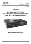
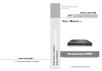
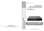
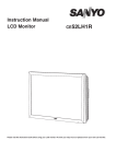
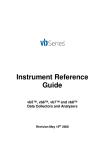
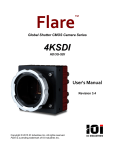
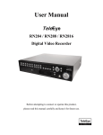
Thank you for purchasing our product.
Please read this User s Manual before
using the product.
STAND-ALONE DVMR
16 Channel Digital Video Multiplex Recorder
16 CHANNEL STAND-ALONE DVMR
ALL ABOUT IMAGE RECOGNITION & PROCESSING
DIGITAL VIDEO RECORDER
User s Manual
VER1.1
16 channel
Stand-alone DVMR
The most stable and reliable real stand-alone Digital Video Multiplex Recorder
ALL ABOUT IMAGE RECOGNITION & PROCESSING
Table of Contents
16 channel stand-alone DVMR
4. Configuration
16 channel stand-alone DVMR
ALL ABOUT IMAGE RECOGNITION & PROCESSING
ALL ABOUT IMAGE RECOGNITION & PROCESSING
2. Configuration of Stand-alone DVMR
Chapter 1 . Product package
1-1. The contents of package
3
1-2. Name and function of each button (front panel)
1-3. Name and function of each button (Rear panel)
4
5
Chapter 2. Installation procedure
2-1. Camera connection
6
2-2. Monitor connection (Composite monitor)
6
2-3. Monitor connection (S-VHS)
7
2-4. VCR & VIDEO printer connection
7
2-5. Sensor connection
8
2-6. Network connection
8
2-7. HDD connection
9
2-8. Power connection
9
3. RS-232C ASCII-code table
Chapter 3. Operation
3-1. Basic Display
10
3-2. DVR SYSTEM Log-in
11
3-3. Recording
12
3-4. Playback
15
3-5. Set-up
17
1. Basic operation
17
2. CAMERA SETUP
18
3. ADJUST COLOR
18
4. MOTION SETUP
19
5. SET/TIME DATE
20
6. RECORD SETUP
7. HDD MANAGEMENT
20
21
8. MISCELLANEOUS SETUP
21
9. TCP/IP SETUP
24
10. FACTORY DEFAULT
24
Chap 4. Specification and Configuration
4-1. SPECIFICATIONS
25
4-2. Configuration Stand-alone DVMR
26
4-3. RS-232C Hex-code table
26
4-4. Arrange of RS 485 and RS-232C pin
26
1
Following ASCII-code are for programmers who want to control DVMR unit via RS-232C port.
RS-232C specification (baud rate/parity/data length/stop bit) : 57600, N, 8, 1
1 Byte ASCII-code
MODE
‘D’
PIP
‘I’
‘<’
CH1
‘1’
CH5
‘5’
CH9
‘9’
CH13
‘#’
MENU
FRZ
‘F’
P/T
‘T’
‘P’
CH2
‘2’
CH6
‘6’
CH10
‘0’
CH14
‘$’
ENTER
SEQ
‘Q’
‘R’
‘>’
CH3
‘3’
CH7
‘7’
CH11
‘!’
CH15
‘%’
LEFT
H
ZOOM
‘Z’
‘S’
‘A’
CH4
‘4’
CH8
‘8’
CH12
‘@’
CH16
‘^’
RIGHT
K
4. Arrangement of RS 485 and RS-232C pin
Pin No.
1
2
3
4
5
6
7
8
9
Definition
NC
RxD
TxD
SD-(RS 485)
GND
SD+(RS 485)
NC
NC
NC
C o m m
P ort
1
5
6
9
RS-232C
26
‘M’
UP
U
DN
J
4. Configuration
16 channel stand-alone DVMR
16 channel stand-alone DVMR
ALL ABOUT IMAGE RECOGNITION & PROCESSING
ALL ABOUT IMAGE RECOGNITION & PROCESSING
Chapter 4 . Specification and configuration
About this manual
1. SPECIFICATIONS
MODEL NO
16 channel stand-alone Digital Video Multiplex Recorder
Before installing stand-alone DVMR, be sure to thoroughly review and follow the instructions in this
VIDEO I/F
MONITORING
METHOD
RECORDING
/PLAY
FUNCTION
INPUT
OUTPUT
HORIZONTAL RESOLUTION
S/N RATIO
COLOR
SPLIT SCREEN
ZOOM
PIP
SEQUENCE
16 CH INPUT 1.0 VP-P, 75 OHM UNBALANCED (BNC TYPE)
3 OUTPUT VBS : 1.0VP~P.75 OHM UNBALANCED (BNC TYPE)
480TV LINES
MORE THAN 4dB
16.7 MILLION
FULL, QUAD, 9 SPLIT , 16 SPLIT DISPLAY
LIVE & PB AVAILABLE
AVAILABLE
AVAILABLE
DIAPLAY QUALITY
FULL : 720(H)X480(V) ACTIVE PIXELS/FULL MOVING PICTURE
1/16 SCREEN :180(H)X120(V) ACTIVE PIXELS
SPEED
STORAGE MEDIA
COMPRESSED PICTURE
PICTURE PRESERVATION
METHOD
REC, MODE
TRACK PLAY
User’s Manual. Pay particular attention to the parts that are marked NOTICE.
Also, when connecting with external application, first turn the power OFF and follow manual instruction for
appropriate installation.
Before reading this manual
MAX 30 FRAME/SEC
HDD
JPEG
FIELD SWITCHER METHOD FULL SCREEN PRESERVATION
REAL-TIME/ TIME-LAPSE / EVENT/ MOTION
SEARCH, STILL
1. This document is intended for both the administrator and users of stand-alone DVMR model.
2. This manual contains information for configuring, managing and using stand-alone DVMR model.
3. Be sure to read through this manual before using this stand-alone DVMR model.
OTHER
FUNCTION
BACK-UP
VCR, TIME LAPS VCR : VCR OUTPUT
OTHERS
RS232C, RS485, 16 ALARM INPUT ,1 RELAY OUTPUT
CAMERA CONTROL
CONFIGURATION
PLUG&PLAY
HDD EXPANSION
IN DVMR CASE : 1 OR 2 HDD
OPTIONAL HDD BAY SUPPORTED
MAX 20 HDD EXPANDABLE
COMPATIBILITY WITH DIFFERENT MANUFACTURER OF HDD
OPERATION TEMPERATURE
MECHANICAL
PAN/TILT/ZOOM AND FOCUS
REMOTE CONTROL : EXTERNAL EQUIPMENT, WIPER,PUMP,FAN
AND HEATER
OPERATION HUMIDITY
IR REMOTE
DIMENSION
WEIGHT
POWER SUPPLY
41F~ 104F (5C~ +40C)
LESS THAN 90%
BUILT-IN
19" RACK SIZE 1U , 44X434X360 mm
APPROX. 5KG (HDD 1EA)
DC ADAPTER ( 12V DC 4.5A)
25
4. To prevent fire or electrical shock, do not expose the product to heat or moisture.
5. Check electricity at the place you want to install the DVMR unit if it is stable and meets our electricity
requirements. Unstable electricity will cause malfunction of the unit or give critical damage to
the unit.
6. Several chips on the main board of the DVMR unit and hard disk drive inside the unit generate
heat, and it must be properly discharged.
Do not put any objects just beside exhaust port(fan) on the left side of the unit and do not close
up an opening (fresh air in-take) on the right side of the unit.
7. Put the DVMR unit at well-ventilated place and do not put heat-generating objects on the unit.
When it is installed inside 19 inch mounting rack together with other devices, please check builtin ventilation fan of the rack is properly running.
8. For questions and technical assistance of this product, contact your local dealer.
2
1. Product package
16 channel stand-alone DVMR
3. Operation
16 channel stand-alone DVMR
ALL ABOUT IMAGE RECOGNITION & PROCESSING
ALL ABOUT IMAGE RECOGNITION & PROCESSING
f. PASSWORD SETUP.
To input user’s own password in the first operation or to change pwassword.
Chapter 1 . Product Package
1-1. The contents of package
SYSTEM SETUP
1. 16 ch stand-alone DVMR unit
CAMERA SETUP
TIME/DATE SETUP
RECORD SETUP
HDD MANAGEMENT
MISCELLANEOUS SETUP
TCP/IP SETUP
FACTORY DEFAULT
Record data of pictures from camera on hard disk drive, after converting it into digital data.
BUZZER SETUP
ALARM SETUP
TIMER SETUP
PAN/TILT CMD SETUP
BAUDRATE SETUP
PASSWORD SETUP
Current password
CURRENT PASSWORD
:________
NEW PASSWORD
:________
New password
CONFIRM PASSWORD
:________
New password to confirm
INPUT YOUR OWN PASSWORD,
THEN PRESS [ENTER]
TO EXIT, PRESS [MENU]
POWER
RECORD
Display of PASSWORD SETUP
Move using [Up] and [Down] buttons and input your own password by pressing any buttons on the front of DVMR
unit. Length of password is from 1 to 8. To change password, first input current password and then new
password. You have to input new password again to confirm.
CAMERA
OVERWRITE
MODE
F RZ
SE Q
ZOOM
P IP
P /T
1
2
3
4
5
6
7
8
ME NU
9
10
11
12
13
14
15
16
E NTE R
PLAY
SET UP
Notice : Password set by manufacturer before delivery(FACTORY DEFAULT) is null, and just press [MENU] and
then press [ENTER] to enter into SETUP menu.
2. User manual for 16 ch DVMR
Describe how to install and operate this DVMR unit.
Stand-alone DVR
Notice : In the first operation, we recommend you to set own password.
In case you forgot own password, contact dealer to know how to get into SETUP menu.
IR remote controller enables to operate DVMR unit apart from the unit.
4. DC power adapter and power cable
DIGITAL VIDEO RECORDER
9. TCP/IP SETUP
3. Remote controller
16 channel
Stand-alone DVR
ALL ABOUT IMAGE RECOGNI TION & PROCESS ING
Convert AC 110V or AC 220V into DC 12V to supply to DVMR unit.
In case TCP/IP option is included, you have to input IP address, Port number, Subnet Mask and Gateway into
TCP/IP SETUP of DVMR unit. If DVMR Unit is connected to leased line with static IP, ADSL with static IP or
dynamic IP, or cable modem with dynamic IP, you can access to DVMR unit via Internet line to see live pictures
or search recorded pictures, far apart from DVMR unit. In case both DVMR unit and client PC are connected to
the same LAN network(Intranet), you can access to DVMR unit from the client PC, but somebody outside Intranet
can not access to DVMR unit via Internet line. In all cases, you have to install client program(Remote Viewer) on
the client PC from which you want to access to DVMR unit. For more details, refer to Remote viewer manual for
16 ch DVMR included in the package.
10. FACTORY DEFAULT
Initialize system setup as settings recomended by manufacturer (FACTORY DEFAULT).
FACTORY SETUP
SYSTEM SETUP
CAMERA SETUP
TIME/DATE SETUP
RECORD SETUP
HDD MANAGEMENT
MISCELLANEOUS SETUP
TCP/IP SETUP
FACTORY DEFAULT
ALL SETUP
---
CAMERA COLOR
NO
CAMERA TITLE
MOTION MASK
NO
NO
PAN/TILT COMMAND
SYSTEM STATUS
NO
NO
RUN
SELECT
, EDIT ENTER
5. Accessories (Rack mount bracket and bolts)
Mounting bracket and bolts necessary for fixing DVMR unit into 19 inch rack, and batteries for remote controller.
Display of FACTORY SETUP
You can set all groups of settings as a whole or set them group by group. Move to menu items using [Up] and
[Down] buttons and select “YES” or “NO”, and then move to “RUN”. Press [ENTER] button to set at
FACTORY DEFAULT for selected group of settings.
Notice : When you connect or replace new HDD, set at FACTORY DEFAULT before starting to record.
3
24
3. Operation
16 channel stand-alone DVMR
1. Unit Description
16 channel stand-alone DVMR
ALL ABOUT IMAGE RECOGNITION & PROCESSING
ALL ABOUT IMAGE RECOGNITION & PROCESSING
1-2. Name and function of each button
d. PAN/TILT CMD SETUP.
Input protocol of PTZ camera or speed dome camera which shall be controlled by data communication
via RS-485. Max. length of protocol for each command is 15 Byte, and Baud rate is settable from 1200 to 19200.
Max. 4 PTZ cameras can be connected to DVMR unit.
[ Front Panel ]
1
2
3
4
5
6
7
8
FRZ
SEQ
ZOOM
PIP
P/T
16
PAN/TILT CMD STEUP
DEV : 1 ST
CMD : POWER ON
LEN : 00 BYTE
SYSTEM SETUP
CAMERA SETUP
TIME/DATE SETUP
RECORD SETUP
HDD MANAGEMENT
MISCELLANEOUS SETUP
TCP/IP SETUP
FACTORY DEFAULT
NO
_
_
01
02
03
04
05
06
07
08
BUZZER SETUP
ALARM SETUP
TIMER SETUP
PAN/TILT CMD SETUP
BAUDRATE SETUP
PASSWORD SETUP
__
:
:
:
:
:
:
:
:
_HEXA
___
00
00
00
00
00
00
00
00
COPY
: REC
SELECT :
CAMERA
POWER
OVERWRITE MODE
NO
_
_
09
10
11
12
13
14
15
__
:
:
:
:
:
:
:
1
2
3
4
5
6
7
8
9
10
11
12
13
14
15
16
MENU
RECORD
_HEXA
___
00
00
00
00
00
00
00
PLAY
SETUP
ENTER
PASTE : PLAY
9
EDIT : NUMERIC/
- Setting sequence
1. DEV : From 1st to 4th.
DEV represents device(model of PTZ camera).
We can connect up to 4 cameras with different protocols. Display of PAN/TILT CMD SETUP
2. Select command
3. Set Byte of command : max. 15. Byte of commands not used for each device must be set at 0.
4. Input protocol of selected command
5. Repeat process from 1 to 4 until you complete to input protocol for all commands you need.
* Use [Record] button to copy and [Playback] button to paste, in case there are many protocols
similar to each other.
- How to input protocol
User must select commands needed for PTZ cameras (from 1st to 4th DEV), and input LEN and
protocol(Hexa-code). For commands not used for your PTZ camaeras, LEN value must be set at 0.
Commands whose LEN are 0 are not shown when you practically control PTZ camera later.
10
11
12
13
14
15
17 18
19
1. POWER SWITCH WITH LED : DC power on-off switch with built-in LED
2. LED : Indicates the status of system
3. MODE : Press [MODE] button and [1], [2], or [3] to change to 4-split, 9-split, or 16-split screen, respectively.
If you press this button for a long time, it changes monitor type from(to) Composite to(from) VGA,
in case DVMR unit supplied includes VGA option.
If you press this button 2 times consecutively, it changes to screen position adjustment mode. In case
position of 16-split screen is not in the center of display unit, you can adjust screen position using [UP],
[DOWN], [LEFT], and [RIGHT] button. After adjustment, press [MSD] button once more to exit.
4. FRZ : On-off switch to freeze pictures in live mode
5. SEQ : In full screen, this button shows pictures in rotation.
6. ZOOM : In full screen, this button enlarges pictures two times ( Possible to fix area to be enlarged using
direction buttons.)
7. PIP : In full screen, this button creates PIP( Picture In Picture ) in rotation.
Using [Up] and [Down] buttons, move to item you want to select or set, and use [Left] and [Right] buttons to
set values.
You can input protocol using numerical buttons on the front of DVMR unit or remote controller.
Following table shows buttons corresponding to each HEX-code for protocol.
HEX-code
1 2 3 4 5 6 7 8 9 A
B C
D E
F
0
Button on the front
1 2 3 4 5 6 7 8 9 10 11 12 13 14 15 16
Button on remote controller
1 2 3 4 5 6 7 8 9 0,0 0,1 0,2 0,3 0,4 0,5 0,6
8. P/T : Enter into or exit from PAN/TILT CONTROL mode
9. Record (
10. Stop (
): Records picture data on hard disk drive
): Stops recording or playback
11. Fast backward (
12. Playback (
Note : For more details, refer to “How to incorporate PTZ protocol for 16 ch DVMR” included in the package.
) : Playback when it is pressed shortly in stop mode, or playback in reverse direction
when it is pressed in playback mode.
Enter into GO TO menu in case pressed in longer time in stop mode.
13. Fast Forward (
e. BAUDRATE SETUP
BAUDRATE SETUP
1200 BPS
2400 BPS
4800 BPS
9600 BPS
19200 BPS
SYSTEM SETUP
CAMERA SETUP
TIME/DATE SETUP
RECORD SETUP
HDD MANAGEMENT
MISCELLANEOUS SETUP
TCP/IP SETUP
FACTORY DEFAULT
BUZZER SETUP
ALARM SETUP
TIMER SETUP
PAN/TILT CMD SETUP
BAUDRATE SETUP
PASSWORD SETUP
CURRENT RATE
1200 BPS
): High speed playback in forward direction in playback mode, or moving to the last
of recorded data when it is in stop mode.
): Pauses when it is in palyback mode
15. Camera No : Represents camera numbers. Used with MSD button or to enter numbers.
16. MENU : Used to change menu in SYSTEM SETUP
CONFIRMATION VIA RS485 PORT
SELECT :
14. Pause (
) : High speed playback in reverse direction in playback mode, or moving to the
start of recorded data when it is in stop mode
THEN ENTER
17. ENTER : Used as selection key in SYSTEM SETUP or changes contents displayed in live display.
By pressing this button repeatedly in live display mode, contents of display, that are, time and date,
DVMR status, and camera title, is included or excluded, and you can select any one of 8 choices.
18. IR receiver : If blocked up by any object, remote controller does not work.
Set baudrate of PTZ camera to be connected.
(1200, 2400, 4800, 9600, and 19200 BPS)
19. Direction key : Used to move in SETUP menu, or to change values
Display of BAUDRATE SETUP
If you connect DVMR unit to your PC by 485 to 232 converter,
you can see data transmitted using program like Windows Hyper-terminal.
23
Notice : If several keys are pressed at the same time, or improper sequence in pressing
buttons may cause malfunction of DVMR unit.
4
1. Unit Description
16 channel stand-alone DVMR
3. Operation
16 channel stand-alone DVMR
ALL ABOUT IMAGE RECOGNITION & PROCESSING
ALL ABOUT IMAGE RECOGNITION & PROCESSING
1-2. Name and function of each button
C
o
m
m
P
b.Set type of sensor(alarm)
o r t
[ Rear Panel ]
1
CH1
CH1
CH2
CH2
CH3
CH3
CH4
CH4
CH5
CH5
CH6
CH6
CH7
CH7
CH8
3
CH9
CH8
CH9
CH10
CH10
CH11
CH11
CH12
CH12
CH13
CH13
CH14
CH14
CH15
CH15
CH16
5
VCR
CH16 MONITOR S-VHS
7
6
ALARM SETUP
SYSTEM SETUP
ALARM/ RELAY
VGA
RS-232C/485
C
o
m
m
P
o
r t
TERATRAY CONNECTION
rks
LOOP
4
2
8
ETHERNET
9
10
DC 12V
CAMERA SETUP
TIME/DATE SETUP
RECORD SETUP
HDD MANAGEMENT
MISCELLANEOUS SETUP
TCP/IP SETUP
FACTORY DEFAULT
ALL
:__
CH 01 :
CH 03 :
CH 05 :
CH 07 :
CH 09 :
CH 11 :
CH 13 :
CH 15 :
BUZZER SETUP
ALARM SETUP
TIMER SETUP
PAN/TILT CMD SETUP
BAUDRATE SETUP
PASSWORD SETUP
NO
NO
NO
NO
NO
NO
NO
NO
CH 02:
CH 04 :
CH 06 :
CH 08 :
CH 10 :
CH 12 :
CH 14 :
CH 16 :
NO
NO
NO
NO
NO
NO
NO
NO
RELAY : ENABLE
NO………..NORMAL OPEN
NC………..NORMAL CLOSE
_ _..............DISABLE
11
SELECT
, EDIT ENTER/
1. CH1~CH16 : Connect cameras of NTSC or PAL system up to 16
Display of ALARM SETUP
2. CH1~CH16 : Loop out from each camera from 1 to 16
3. VCR : Analog Backup output for VCR or video printer
4. MONITOR : Connect to composite monitor in NTSC or PAL system
Set type of alarm sensors connected to DVMR unit. Set at NO (Normal Open) or NC (Normal Close) for alarm
sensors. Set at DISABLE or ENABLE for relay output.
Move to item you want to change using [Up] and [Down] buttons, change type using [Left] and [Right] button.
To set altogether as a whole, locate cursor at “ALL ; --“ and select type you want using [Left] and
[Right] button.
Just exit and all setting is memorized by the system.
5. S-VHS : Connect to S-VHS monitor for better quality of display
c. Time Interval Setting
6. VGA : Connect to PC monitor
7. ALARM/ RELAY : Connect to alarm input and relay output
8. RS-232C/485 : Connect to external device of RS-232C or RS-485 protocol
(RS-232C : Control DVMR using PC keyboard, RS-485 : PTZ camera control
9. TERATRAY CONNECTION : Connect to HDD BAY for extension of HDD space
10. ETHERNET : Connect to Ethernet port for TCP/IP option
TIMER SETUP
SYSTEM SETUP
CAMERA SETUP
TIME/DATE SETUP
RECORD SETUP
HDD MANAGEMENT
MISCELLANEOUS SETUP
TCP/IP SETUP
FACTORY DEFAULT
BUZZER SETUP
ALARM SETUP
TIMER SETUP
PAN/TILT CMD SETUP
BAUDRATE SETUP
PASSWORD SETUP
FULL SCREEN
QUAD, 9SPLIT
: 1 SEC
: 3 SEC
PIP SCREEN
: 2 SEC
SELECT
, EDIT ENTER/
11. D/C 12V : Port for DC 12V, 4.5A
Notice : Improper DC power supply to DVMR unit may cause damage to the sysem.
Notice : When connect to other devices, make sure to turn off DC power switch on the front.
Display of TIMER SETUP
Set time interval for SEQ, PIP (Picture in picture).
FULL SCREEN : Time interval of pictures rotating in channel sequence when [SEQ] button is pressed.
QUAD, 9 SPLIT : Time interval of pictures rotating in a certain sequence when [SEQ] button is pressed.
Pattern of rotation in quad rotation is 1/2/3/4, 5/6/7/8, 9/10/11/12, 13/14/15/16, 1/2/3/4, and so on.
Pattern of rotation in 9-split is 1/2/3/4/5/6/7/8/9, 1/2/10/11/12/13/14/15/16, 1/2/3/4/5/6/7/8/9, and so on.
PIP SCREEN : Time interval of small pictures rotating in sequence when [PIP] button is pressed.
5
22
3. Operation
16 channel stand-alone DVMR
2. Installation
16 channel stand-alone DVMR
ALL ABOUT IMAGE RECOGNITION & PROCESSING
ALL ABOUT IMAGE RECOGNITION & PROCESSING
Chapter 2. Procedure
7. HDD MANAGEMENT
SYSTEM SETUP
CAMERA SETUP
TIME/DATE SETUP
RECORD SETUP
HDD MANAGEMENT
MISCELLANEOUS SETUP
TCP/IP SETUP
FACTORY DEFAULT
2-1. Camera connection
HDD CLEAR
HDD INFORMATION
Connect camera to the CAMERA INPUT (1~16 ) on the rear panel of unit.
HDD MANAGEMENT
HDD CLEAR [IN USE]
HDD INFORMATION
HDD INFORMATION
HDD CLEAR
ENTER PASSWORD : _ _ _ _ _ _ _ _ _
SELECT
, PRESS ENTER
INPUT YOUR OWN PASSWORD,
THEN PRESS [ENTER]
DETECT
: 01/22 ( 61.47 Gbyte)
DRIVE
MODEL
SERIAL
SIZE
: 01
: IC35L0604VV407-0
:
VNC302A3L2ZSWA
: 61.47 GByte
DRIVE
MODEL
SERIAL
SIZE
: 02
:
:
:
DRIVE
MODEL
SERIAL
SIZE
: 03
:
:
:
DC
LEVEL
V.P
VIDEO
CH1
CH16
VCR
CH1
CH16 MONITOR
DC
S-VHS
VIDEO
COPY : REC PASTE: PLAY
SELECT : ↑↓ EDIT : NUMERIC/←→
TO EXIT, PRESS [MENU]
LENS
AC24V/DC12
LOOP
Rear view of CAMERA
Display of HDD MANAGEMENT
a. Clear data stored on HDD.
When “HDD CLEAR [IN USE]” is displayed, press [ENTER] button and input password you already set.
If you entered correct password, HDD shall be cleared and “HDD CLEAR [EMPTY]” is displayed.
Notice : This DVMR system accepts camera with both PAL system or NTSC system, and
you are requested to set at PAL or NTSC system when you first boot, as per
specified in the procedure for selection of video system in 2-8 power connection.
Connect camera and monitor while DC power switch on the front panel is off.
b. Show information of HDDs installed inside DVMR unit or HDD Bay.
2-2. Monitor connection (Composite monitor)
8. MISCELLANEOUS SETUP
a. BUZZER ON/OFF
Connect the monitor to the MONITOR OUT on the rear panel of unit.
BUZZER SETUP
SYSTEM SETUP
CAMERA SETUP
TIME/DATE SETUP
RECORD SETUP
HDD MANAGEMENT
MISCELLANEOUS SETUP
TCP/IP SETUP
FACTORY DEFAULT
BUZZER SETUP
ALARM SETUP
TIMER SETUP
PAN/TILT CMD SETUP
BAUDRATE SETUP
PASSWORD SETUP
ALL BUZZER
KEY BEEP
LOSS EVENT
ALARM EVENT
MOTION EVENT
SELECT
: ___
: ON
: OFF
: ON
: OFF
For all buzzers
Button buzzer
Video loss buzzer
Alarm activated buzzer
Motion detected buzzer
CH1
CH16
VCR
CH1
CH16 MONITOR
, EDIT ENTER/
S-VHS
LOOP
VIDEO A
IN
Display of BUZZER SETUP
Press [Up] and [Down] buttons to move to item you want to set, and select using [Left] and [Right] button.
Press [ENTER] button to set. To set altogether at ON or OFF, move to ALL BUZZER and set at ON or OFF.
21
6
OUT
VIDEO B
IN
OUT
VIDEO C
IN
OUT
2. Installation
16 channel stand-alone DVMR
3. Operation
16 channel stand-alone DVMR
ALL ABOUT IMAGE RECOGNITION & PROCESSING
ALL ABOUT IMAGE RECOGNITION & PROCESSING
5. SET TIME/DATE
Sets Year/Month/Day/Hour/Minute/Second.
2-3. Monitor (S-VHS) connection
Using [Up] and [Down] buttons, move to menu item,
and change value using [Left] and [Right] buttons.
Connect S-VIDEO monitor to MONITOR OUT (S-VHS) on the rear panel of unit.
SET TIME/DATE
YEAR
MONTH
DAY
HOUR
SYSTEM SETUP
MINUTE
SECOND
CAMERA SETUP
TIME/DATE SETUP
RECORD SETUP
HDD MANAGEMENT
MISCELLANEOUS SETUP
TCP/IP SETUP
FACTORY DEFAULT
SELECT ↑↓ , PRESS←→
6. RECORD SETUP
VIDEO A
CH1
CH16
CH1
CH16 MONITOR
VIDEO B
VIDEO C
VCR
IN
OUT
S-VHS
LOOP
IN
OUT
IN
OUT
Setting for recording
a. Press [MENU] button and enter password and press
[ENTER] button to enter into main SETUP menu.
In the main SETUP menu, select RECORD SETUP.
Default password set by manufacturer is null, therefore
just press [ENTER] button after you press [MENU] button
to enter into main SETUP menu, in case you did not
change password.
b. Select RECORD TYPE.
-TIMER : Recording at a certain time interval (DEFAULT)
-MOTION : Recording when a motion detected
-ALARM : Recording when an alarm is activated
c. Decide to overwrite or not when HDD is full.
-OFF : Stop recording when HDD is full.
-ON : Overwrite when HDD is full (DEFAULT).
2-4. VCR & VIDEO PRINTER Connection
Display of SET TIME/DATE
RECORD SETUP
RECORD TYPE
OVERWRITE
TIME INTERVAL
EVENT OFF TIMER
REFRESH RATE
DURATION
SELECT
Connect VCR or Video printer to VCR OUT on the rear panel of unit.
VCR
CH1
CH16
VCR
CH1
CH16 MONITOR
S-VHS
VIDEO PRINTER
LOOP
: TIMER
: OFF
: 1/1X
: 60 SEC
:______
:______
, PRESS
d. Total recording rate (Fields/sec)
-1/1X : Records at maximum rate/60(50) Fields/sec in total
( FACTORY DEFAULT)
-1/2X: Records at half of maximum rate/
30(25) Fields/sec in total
Display of RECORD SETUP
- Possible to set from 1/1X to 1/999X.
- If you set at 1/480X, it corresponds to 960 hours recording mode in Time Lapse VCR.
e. REFRESH RATE : In Motion or Alarm recording mode, DVMR system records pictures at a certain time
interval (REFRESH RATE) even though there is no motion detected or alarm activated.
-20 SEC : Records pictures from all channels at time interval of 20 sec, regardless of motion detected
or alarm activated.
f. DURATION : Records for DURATION time when a motion is detected or an alarm is activated.
- 20 SEC : Records pictures from a channel where motion is detected or alarm is activated, for 20 sec.
- 1 SEC : FACTORY DEFAULT
g. EVENT OFF TIMER : To limit numbers of motion detected, alarm activated or video loss to be enlisted to event
list, we set EVENT OFF TIMER.
- 60 SEC : Just in case time interval between previously detected motion (alarm or loss) and currently detected
motion (alarm or loss) is longer than 60 sec, currently detected motion(alarm) is enlisted in event list.
60 SEC is FACTORY DEFAULT.
- EVENT OFF TIMER is to protect event list from being filled with motion, alarm, or video loss detected very
frequently. If time interval between previous motion(alarm or loss) and current motion(alarm or loss) is
shorter than set EVENT OFF TIMER, motion, event, or video loss is not enlisted in event list, but
recording is done as set(if it is set at Motion recording or Alarm recording).
7
20
3. Operation
16 channel stand-alone DVMR
2. Installation
16 channel stand-alone DVMR
ALL ABOUT IMAGE RECOGNITION & PROCESSING
ALL ABOUT IMAGE RECOGNITION & PROCESSING
2-5. Sensor connection
4. MOTION SETUP
Sets motion detection area and sensitivity of motion to be detected.
When motion is detected, it is changed
to green color and glittering.
CELL
ON
SYSTEM SETUP
CAMERA SETUP
TIME/DATE SETUP
RECORD SETUP
HDD MANAGEMENT
MISCELLANEOUS SETUP
TCP/IP SETUP
FACTORY DEFAULT
EDIT CAMERA TITLE
ADJUST COLOR
MOTION SETUP
CAM 01
X08Y07
Motion detection menu
Channel in setting
and coordinates
of current cell
Connect sensors to D-SUB 25 Pin as specified below.
You can connect dry-contact type sensors. In case of sensors with TTL output (5 Volts system), GND of
sensor must be connected to GND of DVMR unit and signal line to alarm input from D1 to D16 as shown in
following figure.
Short-circuit between any of D1 from D16 and GND is recognized as an alarm.
SENSOR
Current sell
5
D9
SELECT : MENU
EDIT : ENTER/↑↓ ←→
6
D6
D5
GND
GND
D4
D3
D2
D1
13
12
11
10
9
8
7
6
5
4
3
2
1
9
25
11
24
23
22
21
20
19
18
17
16
15
14
10
D8
13
D9
14
D10
NC
COM
NO
D16
D15
D14
D13
GND
GND
D12
D11
D10
15
D11
12
16
D12
19
D13
RELAY Output
17
20
D14
21
D15
18
Relay output is output in case there is an alarm input, and is connected to external
device using COM-NO (Normal Open) or COM-NC (Normal Close) contact.
22
D16
Sets motion detection area by block(X x Y).
Using direction keys, select the first location of cell and press [ENTER] button, and then select the second location of
cell using direction keys and again press [ENTER] button.
You will see color of all cells inside 2 coordinates is changed to green, motion detection area.
2-6. Network connection
RS-232C : Connected to RS-232C port of PC to operate DVMR unit with key-board of PC.
All cells are set as a detection area or no detection area.
RS 485 : Connected to P/T Controller or Speed Dome Camera
When it is in ALL-OFF, press [ENTER] make all cells no detection area. When it is in ALL-ON, press
[ENTER] to make all cells detection area.
SENSITIVITY
LEVEL 10
D7
8
D7
Sets motion detection area cell by cell.
Using direction keys, select cell to set and press [ENTER] button. Color of cell set is changed to green.
D8
7
D6
CELL
ON(OFF)
GND
4
D4
Display of MOTION SETUP
Basic display : Press [MENU] button repeatedly until you find menu item to set, and select by
pressing [ENTER] button.
In basic display of MOTION SETUP, green colored cell represent motion detection area.
GND
3
D5
ALL
OFF(ON)
GND
2
D2
D3
BLOCK ON
BEGIN
END
All GNDs are connected to each other on circuit.
1
D1
RJ-45 : Connected to LAN, WAN or Internet
Sets sensitivity of motion detection.
Using [Up] and [Down] buttons, choose sensitivity level.
LEVEL 01(Dull)
DETECT WINDOW
NUMBER 01
C
VGA
o
m
m
P
ALARM/ RELAY
o r t
PC
RS-232C/485
C
o
m
m
P
o r t
LEVEL 10(Sensitive)
Sets numbers of cells corresponding to size of motion.
Just in case numbers of cell detected (green colored) is more than set numbers, motion is detected.
If you set DETECT WINDOW NUMBER at bigger number, motion by small object is not detected.
Press [Up] and [Down] buttons to increase or decrease cell number.
PTZ
CAMERA
TERATRAY CONNECTION
PC
rks
ETHERNET
DC 12V
Notice :TERATRAY CONNECTION port must be used for connecting HDD Bay (TeraTray), and can not be
used for connecting other device. Connection must be done while power supply to DVMR unit is cut.
Exit
To exit, press [ENTER] button.
When TeraTray is connected to DVMR unit, supply power to TeraTray first and then to DVMR unit.
19
8
2. Installation
16 channel stand-alone DVMR
3. Operation
16 channel stand-alone DVMR
ALL ABOUT IMAGE RECOGNITION & PROCESSING
2-7. HDD Connection
Specification of HDD : EIDE, 7200 rpm, LBA mode type(Up to 120GB)
ALL ABOUT IMAGE RECOGNITION & PROCESSING
2. CAMERA SETUP
Sets camera titles for display in full screen, 4-split screen, and 9-split screen.
1
HDD 1
MAIN BOARD
HDD 2
EDIT CAMERA TITLE
2
CAM
CAM
CAM
CAM
CAM
CAM
CAM
CAM
CAM
CAM
CAM
CAM
CAM
CAM
CAM
CAM
SYSTEM SETUP
POWER
CAMERA
OVERWRITE
M ODE
RECORD
FRZ
SE Q
ZOOM
P IP
P /T
1
2
3
4
5
6
7
8
ME NU
9
10
11
12
13
14
15
16
ENTE R
PLAY
SETUP
Connect main board and HDD using IDE HDD cable and power cable included in the package.
CAMERA SETUP
TIME/DATE SETUP
RECORD SETUP
HDD MANAGEMENT
MISCELLANEOUS SETUP
TCP/IP SETUP
FACTORY DEFAULT
EDIT CAMERA TITLE
ADJUST COLOR
MOTION SETUP
1
2
3
4
5
6
7
8
9
10
11
12
13
14
15
16
..
..
..
..
..
..
..
..
..
..
..
..
..
..
..
..
.
.
.
.
.
.
.
.
.
.
.
.
.
.
.
.
..
..
..
..
..
..
..
..
..
..
..
..
..
..
..
..
..
..
..
..
..
..
..
..
..
..
..
..
..
..
..
..
.
.
.
.
.
.
.
.
.
.
.
.
.
.
.
.
[
[
[
[
[
[
[
[
[
[
[
[
[
[
[
[
CH
CH
CH
CH
CH
CH
CH
CH
CH
CH
CH
CH
CH
CH
CH
CH
-0
-0
-0
-0
-0
-0
-0
-0
-0
-1
-1
-1
-1
-1
-1
-1
1
2
3
4
5
6
7
8
9
0
1
2
3
4
5
6
]
]
]
]
]
]
]
]
]
]
]
]
]
]
]
]
,
.
<
>
(
)
=
A
B
C
D
E
F
G
CAM ↑↓ , CHAR ←→, POS ENTER
If you install just a unit of HDD, jumper setting of HDD must be on Master, as specified by HDD
manufacturer, and you can install it at any location of HDD1 or HDD2.
In case you install 2 HDDs, HDD1 must be Master and HDD2 is Slave, and jumper setting must be done
properly as specified by HDD manufacturer.
Display of CAMERA SETUP
Fix HDD on the bottom of DVMR case using screws included in the package. Screws must be inserted
from outside of the bottom.
Notice : Formatting before installation is not required, because DVMR system automatically detects HDD and formats.
In the first operation after installation of HDD, first (clear all data on HDD and) set at FACTORY DEFAULT in
SETUP menu of DVMR system.
2-8. Power connection
Connect DC 12 V power to the POWER CONNECTION on the rear panel of DVMR unit.
a.Press [ENTER] button to move to menu item you want to set.
b.Enter letters (Alphabet, numbers, and symbols) using [Left] and [Right] buttons.
c.Move to next camera for settings using [Up] and [Down] buttons.
d.If you have same word repeated in camera title for each channel, move to the word you want to
copy and press [Record] button for copy and move to the location to put it and press [Playback]
to paste.
3. ADJUST COLOR
DC 12V
CAMERA COLOR SETUP
SYSTEM SETUP
Selection of video system (NTSC/PAL system)
You can set video system in the process of booting. According to video system of camera, set video
system as follows.
NTSC system : While you press [MENU] button and [LEFT] button at the same time, turn DC power
switch on. Press two buttons until you hear beep sound from DVMR unit.
PAL system : While you press [MENU] button and [RIGHT] button at the same time, turn DC power
switch on. Press two buttons until you hear beep sound from DVMR unit.
From next booting, it is not necessary to set as above. DVMR system memorize video setting.
In the process of booting, DVMR system displays “VIDEO SYSTEM SETTING TO NTSC(or PAL)” on
bottom of screen to inform you video system you selected.
Turn on the POWER and Log on the system
Follow direction of Log-in part of this manual to input own password and start the system.
Just press ENTER button if you do not want to input own password.
Detail setup in SYSTEM SETUP :
CAMERA SETUP
TIME/DATE SETUP
RECORD SETUP
HDD MANAGEMENT
MISCELLANEOUS SETUP
TCP/IP SETUP
FACTORY DEFAULT
CH NUMBER
BRIGHTNESS
CONTRAST
SATURATION
HUE
GAIN
EDIT CAMERA TITLE
ADJUST COLOR
MOTION SETUP
SELECT ↑↓ , PRESS ←→
Adjust colors of images from cameras.
Display of COLOR SETUP
CH NUMBER
BRIGHTNESS
CONTRAST
SATURATION
HUE
GAIN
: Select camera # from 1 to 16
: Sets brightness
: Adjust color contrast
: Adjust color saturation
: Adjust color hue
: Adjust image signal level
(-31~ +32)
(-31~ +32)
(-20~ +32)
(-31~ +32)
(-31~ +32)
Refer to SYSTEM SETUP of this manual.
Notice : To connect HDD Bay to DVMR unit, first turn off power to both DVMR unit and HDD Bay.
Then turn on power to HDD Bay first and then DVMR unit after more than about 5 seconds.
9
1
-1
+3
+0
-1
-14
18
3. Operation
16 channel stand-alone DVMR
3. Operation
16 channel stand-alone DVMR
ALL ABOUT IMAGE RECOGNITION & PROCESSING
ALL ABOUT IMAGE RECOGNITION & PROCESSING
Chapter 3 . Operation
3-1. Basic display
3-5. SETUP
Turn on the power switch, and DVMR system shows live display from ch 1 to 16 as following figure.
DVMR system already started to record picture data automatically.
1. Basic operation
Setting camera title, colors, motion, and others
2. Current year/month/day/time
In playback mode, it represents time
of recording
2002 / APR / 01
1
SYSTEM SETUP
PM 01: 00: 00
R
P
TIM
10.56%
9.34%
2
3
4
6
7
8
Setting date and time in local time
CAMERA SETUP
TIME/DATE SETUP
Setting recording type
3. Split screen
Full screen by ch, 4-split, 9-split or
16-split screen are available
5
RECORD SETUP
HDD MANAGEMENT
Clearing data on HDD or HDD information
MISCELLANEOUS SETUP
4. Indicates channel of camera
9
10
11
12
15
16
TCP/IP SETUP
Setting password, PTZ control, buzzer, and alarm
FACTORY DEFAULT
SELECT UP/DOWN ,ENTER
Setting IP address & others
Initialize system and set at FACTORY DEFAULT
Cross color reduction setting : In 16-split live display, user
can set logic level of D/A converter in 3 steps for better
quality of OSD.
13
14
1. indicate current status of DVMR
Recording
Recording stand-by (No motion or alarm detected
in motion or alarm recording mode)
Stop
Playback in forward direction
Playback in backward direction
x times high speed playback in forward direction
x times low speed playback in forward direction
x times high speed playback in backward direction
x times low speed playback in backward direction
Pause ( Temporary stop of palyback)
5. Percentage of HDD space and next playback point
- R : Percentage HDD space used
- P : End of last playback
(Next playback starts from this point)
Status of HDD detected
???.?? : Unknown HDD detected
- - - . - -: No HDD detected
- TIM : TIMER RECORDING
- MOT : MOTION RECORDING
- ALM : ALARM RECORDING
Press [UP] or [DOWN] button to adjust brightness and
color blurred on the edge of letters and at the corner of
object.
Basic display
1. First operation
After power supply, DVMR system automatically starts to record on Timer recording mode.
It is factory default setting, and user can change to other recording settings.
Display of SETUP
a. Press [MENU] button.
a. If press [Playback] button( ) shortly, playback starts from last stop point. If press [Playback] button once
more in playback mode, direction of playback is reversed.
If press [Playback] button in long time while DVMR system is in stop mode, you can enter into GO TO
menu. For details, refer to playback part of this manual.
b. Enter PASSWORD and log on the system.
c. Select SETUP item using [Up] and [Down] buttons.
d. Press [ENTER] button to move to Sub-menu.
e. In Sub-menu, press [Up] and [Down] buttons to move and press [Left] and [Right]
button to set values.
b. If press ( ) button in playback mode, [1x] is displayed, and you can select speed of playback
higher than x1.
If press ( ) button repeatedly, speed of playback is increased from 1, 2, 4, 8, 16, 32, up to 64.
To the contrary, if press ( ) button in playback in x1 speed, playback speed is decreased to ½ and
then ¼.
c. To go back to Menu, press [Menu] button while in stop mode.
f. Press [ENTER] button to select and [MENU] button to exit.
g. All settings done in SYSTEM SETUP is memorized automatically when you exit SETUP menu.
Settings remain unchanged after setting at FACTORY DEFAULT
1. TIME/DATE SETUP
2. All data on HDD
3. Password
4. ALARM LIST SETUP
Notice : We recommend users to clear all data on HDD and set at FACTORY DEFAULT in the very first operation
of this DVMR unit.
In case you added HDD, replaced HDD or replaced EPROM (Program for DVMR unit), also clear data on
HDD and set at FACTORY DEFAULT again.
17
2. Set time when you first operate DVMR unit.
Refer to TIME/DATE SETUP in SYSTEM SETUP in this manual.
3. To enter into 4-split, 9-split, or 16-split screen during live monitoring or playback, press [MSD] button first and
then 1, 2, or 3 respectively.
4 Display of camera channel (camera title)
In 16-split screen, camera title is shown in numbers by the system from 1 to 16, and in 4-split and
9-split screen, camera title set by user is shown.
5. Shows how much space in HDD is recorded
a. R(RECORD) indicates percentage of HDD space used until now.
b. P(PLAY) indicates starting point from which next playback will start. It is the point where last
playback stopped. To start playback from the first of recording, press ( ) button to set P(PLAY) at 0.00%,
and then press [Playback] button ( ).
To replay reverse direction from the end of recording, press ( ) button to move to the end of recording,
and then press [Playback] button ( ).
Notice : If you press [MSD] button for a long time, you can select type of monitor. [MSD] button changes monitor
type (defaulf mode is Composite) from(to) Composite to(from) VGA, whenever pressed, in case VGA
option is included.
If you press [MSD] button two times continuously, you can adjust screen position by pressing [LEFT],
[RIGHT], [UP], and [DOWN] buttons on the front panel of DVMR unit.
10
3. Operation
16 channel stand-alone DVMR
3. Operation
16 channel stand-alone DVMR
ALL ABOUT IMAGE RECOGNITION & PROCESSING
ALL ABOUT IMAGE RECOGNITION & PROCESSING
3-2. DVMR SYSTEM Log-in
4. Speed of playback
2002 / APR / 01
LOGIN DVR SYSTEM
Enter password
Default P/W : [ENTER]
1) After system starts to operate,
press [MENU] button to enter into
SYSTEM menu.
2) LOGIN DVR SYSTEM is displayed as
shown on the left.
ENTER PASSWORD : _ _ _ _ _ _ _ _ _
3) If you want to input for your own password,
press any buttons on the front panel,
from 1 button to 8 buttons.
If you do not want to have own password,
just press [ENTER] button.
INPUT YOUR OWN PASSWORD,
THEN PRESS [ENTER]
TO EXIT, PRESS [MENU]
a. Press [Fast forward]( ) in playback mode.
b. As shown on the left,
1x is displayed, and you can select
high and low playback speed.
c. Press [Fast forward] button repeatedly to increase playback
speed, 1,2,4,8,16,32,64. Press [Fast backward] button to
decrease playback speed to ½ or ¼.
d. You can select high speed and low speed when
1x is
displayed, by pressing [Fast forward] button or
[Fast backward] button.
1X
PM 01: 00: 00
R
P
1
10.56%
5.37%
2
3
4
5
6
7
8
9
10
11
12
15
16
13
14
Display of Playback
High speed/Backward
4) Then press [ENTER] button.
High speed/Forward
Display of Login
64X - 32X - 16X - 8X - 2X - 1X - 1/2X - 1/4X - 1/4X - 1/2X - 1X - 2X- 4X- 8X - 16X -32X - 64X
If password you entered is consistent with password already set, “PASSWORD OK” is displayed, and you
enter into SYSTEM SETUP. If it is not, system goes back to live display mode.
5. ZOOM
Press [ZOOM] button in full screen mode, and picture of that channel is enlarged two times.
Using direction keys, [Up], [Down], [Left], and [Right], you can select area to be enlarged.
This function is available for both in live mode and playback mode.
Factory default password is [ENTER].
Notice : We recommend users to set own password in the first operation. For details, refer to
PASSWORD SETUP IN SYSTEM SETUP-MISCELLANEOUS SETUP.
Notice : Be careful to memorize own password to operate DVMR unit properly.
If you forget password, contact this DVMR dealer to know how to enter into SYSTEM SETUP.
Notice : To protect hard drive from damaged, turn off DC power switch of DVMR unit after you first
press [MENU] button. If you press [MENU] button, DVMR unit stops recording, and HDD
head is not in the process of writing.
6. PAUSE
Pauses pictures during playback.
After pressing [Pause] button, press [Fast forward] or [Fast backward] buttons to move forward or backward in the
unit of field.
If you see pictures in 16-split screen, you can move picture by picture in every channel whenever you press [Fast
forward] or [Fast backward] button.
7. Others
a. DVMR system memorizes status of last playback.
For instance, you searched recorded data in backward playback and stopped at the point of 45% of
total HDD space. In the next playback, DVMR system automatically starts from the point of 45% in reverse
direction. It is for efficiency in search recorded data.
b. If you want to search recorded data from the first of data, press [Fast Backward] button in stop mode.
Then, “P 0.00%” is displayed on the top left, and you can search from the first if press [Playback] button.
If you want to search from the end of recorded data, press [Fast forward] button when in stop mode, then
next playback location is changed to the end of recorded data. If you press [Playback] button, playback
starts from the end in backward direction.
c. During playback, DVMR system does not record.
d. If image data on the date and time you entered in GOTO menu is not exist, playback starts from the picture which
is the nearest to the date and time you set. If the date and time you entered is not between start of recording and
end of recording, playback starts from the nearest point, from the start of recording or end of recording.
11
16
1
3. Operation
16 channel stand-alone DVMR
3. Operation
16 channel stand-alone DVMR
ALL ABOUT IMAGE RECOGNITION & PROCESSING
ALL ABOUT IMAGE RECOGNITION & PROCESSING
3-4. Playback
3-3. Recording
1. Basic operation
1. Basic recording method
Press [Record] button (
), then recording icon (
) is displayed on the top of screen.
If DVMR system is booted again, it is not necessary to set recording settings, because recording
setting remains unchanged and memorized.
Refer to SYSTEM SETUP-RECORD SETUP in this manual. (PAGE. 20)
a. If press [Playback] button( ) shortly, DVMR system starts to replay.
b. If press [Playback] button( ) once again, direction of playback is reversed.
c. If press [Playback] button( ) in long time when DVMR system is in stop mode, you can enter GOTO MENU.
d. Then you can select search by percentage, by time, and by event in GOTO MENU.
2. Example of operation
a.In the picture on the right, 1 represents 10.56% of total HDD space is spent for data recording, and next
playback will start from the point of 5.37% of total HDD space.
b. Press [Playback] button( ).
c. Playback will start at the point of 5.35% of total HDD space.
2002 / APR / 01
PM 01: 00: 00
R 10.56%
d. When [Stop] button( ) is pressed at the point of 9.34%,
P
5.37%
1
2
3
4
DVMR system memorize it(Memorize stop point of last playback).
e. If press [Playback] button( ) again, playback starts from
9.34 %(stop point of last playback).
5
7
8
6
f. When playback proceeds up to 10.56% of total HDD space,
playback is stopped.
9
10
11
12
g. If press [Playback] button( ), playback starts again from the
end of data in reverse direction.
13
14
15
16
h. If press [Stop] button( ), system goes to live display mode.
Unless you press [RECORD] button, DVMR system does not
record.
1
2. FRZ (FREEZE)
If press [FRZ] button, “FRZ” is displayed on top left.
Then press number of channel you want to freeze. Picture of channel you selected is freezed,
and ( F ) icon is displayed on the left of camera title.
Press [FRZ] button again to exit.
3. SEQ (SEQUENCE)
If press [SEQ] button in live display when it is in full screen of any channel, it shows full screen pictures
in rotation.
Rotation time interval can be set in SYSTEM SETUP-MISCELLANEOUS SETUP-TIMER SETUP.
R
P
ABC
D
3. Search
Basic display of playback
When DVMR system is in stop mode, press [Playback] button( )
for a couple of seconds, and you can enter into GOTO MENU.
[PERCENT GOTO]
Start
End
2002 / 04 / 01 10 : 20 : 11
2002 / 04 / 01 13 : 00 : 00
RECORD …………1 0 . 5 6%
PLAY………………._ _ _ _ %
Target ____ / __ / __ __ : __ : __
2002 / APR / 01
PM 01: 00: 00
R
P
1
2
3
10.56%
5.37%
> 6PERCENT
TIME/DATE
EVENT LIST
9
10
13
14
[TIME/DATE GOTO]
7
8
11
12
15
Pictures of 16 channel are displayed in
rotation
Channel rotation in full screen
4. ZOOM
If press [ZOOM] button in full screen of one of 16 channel, system enlarges this picture two times.
Using direction keys on the left of front panel, you can select area to be enlarged.
4
[GOTO MENU]
5
Using buttons from 1 to 10, set
percentage from which you want
to search, then press [ENTER]
button. Time corresponding to
the percentage you set is
displayed, and you can search
by pressing [PLAYBACK] button.
10.56%
9.34%
Start
2002 / 04 / 01 10 : 20 : 11
End
2002 / 04 / 01 13 : 00 : 00
Target
2002 / 04 / 01 11 : 50 : 00
Using [Left] and [Right] buttons,
move to locations you want, and
set values using [Up] and
[Down] buttons.
Then press [Playback] button,
and playback starts from the
time you set.
R
P
10.56%
9.34%
T
Enlarged area moves whenever pressing
direction button, and continuous pressing
make it move faster.
16
[EVENT-LIST GOTO]
> 0 2002 / 04 / 01 10 : 20 : 11
Basic display of GOTO menu
1 2002 / 04 / 01 13 : 00 : 00
2 2002 / 04 / 01 11 : 50 : 00
Select
, Play or Stop
M03
M07
M11
Event list includes information
about motion, alarm, and
camera loss. Using direction
buttons, select event you want to
search, and press [Playback]
button to search.
M : motion , A : alarm, L: loss
M11 : Motion detected at ch #11
15
Current area of picture enlarged
B
L
R
CH-01
Display of ZOOM
12
3. Operation
16 channel stand-alone DVMR
3. Operation
16 channel stand-alone DVMR
ALL ABOUT IMAGE RECOGNITION & PROCESSING
ALL ABOUT IMAGE RECOGNITION & PROCESSING
7. Record setting
5. PIP (PICTURE IN PICTURE)
While you see picture of specific channel in full screen, you can see small size pictures of remaining channels in
rotation, if you press [PIP] button. Time interval of PIP (small size picture) can be set in SYSTEM SETUPMISCELLANEOUS-TIMER SETUP.
If press [SEQ] button while it is in PIP mode, picture in full screen and PIP (small size picture) are all rotate.
a. TIMER recording : Recording by time ( at set recording rate, fields/sec)
Example : Record all images at set recording rate(fields/sec) and overwrite when HDD is full.
1. Log-in to SYSTEM SETUP.
2. Mover to RECORD SETUP and enter.
3. Using direction keys, set as figure-a.
RECORD SETUP
R
P
RECORD TYPE
OVERWRITE
TIME INTERVAL
REFRESH RATE
DURATION
EVENT OFF TIMER
CH2~CH16
Full screen of selected channel
CH-1
RECORD SETUP
10.56%
9.34%
PIP (small size pictures) rotates
in time interval already set
SELECT
RECORD TYPE
OVERWRITE
TIME INTERVAL
REFRESH RATE
DURATION
EVENT OFF TIMER
: TIMER
: ON
: 1/1X
:______
:______
:______
, PRESS
SELECT
: MOTION
: OFF
: 1/1X
: 20 SEC
: 30 SEC
: 60 SEC
, PRESS
b: MOTION recording
a. TIMER recording
Display of PIP
TIME INTERVAL : Images from cameras are coming every 1/60 sec in NTSC system and 1/50 sec in PAL system,
respectively, and it is switching time.
6. P/T (PAN/TILT)
TIME INTERVAL represent recording rate, however it practically indicates if it
records images at time interval of switching time, at time interval of double of
switching time, at time interval of triple of switching time, and so on.
You can connect PTZ camera or speed dome camera to DVMR unit, and you must input protocol of camera to
control camera while you see live pictures, using buttons on the front of DVMR unit or remote controller.
1/1X : Records at all images from all cameras at a time interval of 1/60 or 1/50 second
according video system.
1/2X : Records images from all cameras at a time interval of 2/60 or 2/50 second
according to video system.
a. Basic control button : ENTER - Transmit COMMAND while pressed
UP/DOWN - Selection of menu item
LEFT/RIGHT - Select Command
For details, refer to SYSTEM SETUP-MISCELLANEOUS-PAN/TILT CMD SETUP.
b. MOTION recording : Recording when motion is detected (MOTION DETECTION)
b. Operation : 1. Press [P/T] button.
2. Select device (PTZ camera) using [UP] and [DOWN] buttons.
3. Select Command using [LEFT] and [RIGHT] buttons.
4. After completing input protocols of PTZ camera, press [P/T] button to exit.
Example : Just record for 30 seconds whenever motion is detected, and stop recording when HDD is full.
1. Log-in to SYSTEM SETUP.
2. Move to RECORD SETUP and enter.
3. Using direction keys, set as figure-b.
c. ALARM recording : Recording when alarm is activated
Very similar to MOTION recording
Notice : Maximum numbers of PTZ camera can be connected to DVMR unit is 4.
For details, refer to RECORD SETUP (PAGE. 20) in this manual.
8. Cautions
1) When you are in SYSTEM SETUP, recording is stopped.
2) While DVMR system is in playback mode, recording is stopped.
3) No recording is done in channel to which you did not connect camera.
13
14