1
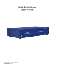
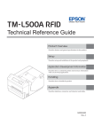
User Manual – Euronet ATB Tool Application & Serial Device Installation USER MANUAL EURONET ATB TOOL APPLICATION & SERIAL DEVICE INSTALLATION Christian Lambert, 2013 Page 1 of 29 User Manual – Euronet ATB Tool Application & Serial Device Installation REVISION HISTORY Version Date Description 1.0 Dec 25 2006 Initial Document 1.1 Aug 13 2007 ATB Tool 2.0 update Sections affected – 3.1, 3.2, 3.4 1.2 Sep 05 2008 Quatech SDS & related documentation update 1.3 Sep 17 2008 Sections changed 4.3.3, 4.4.1, 4.4.2 for button label, LoadLF to Load LFP Christian Lambert, 2013 Author Christian Lambert Vaishal Sheth Christian Lambert Vaishal Sheth Page 2 of 29 User Manual – Euronet ATB Tool Application & Serial Device Installation TABLE OF CONTENTS 1 2 3 4 5 6 7 Introduction ..................................................................................................................................................... 4 IER 723-IP Module ......................................................................................................................................... 4 2.1 Description .............................................................................................................................................. 4 2.2 Configuration .......................................................................................................................................... 4 2.2.1 TCP/IP............................................................................................................................................. 4 2.2.2 IER 723-IP Serial Port Parameters ................................................................................................. 6 2.2.3 IER 557 Serial Port Parameters ...................................................................................................... 8 2.3 Installing Network Interface IER 723-IP to an IER Device ................................................................... 9 2.3.1 Parts Needed ................................................................................................................................... 9 2.3.2 Installation....................................................................................................................................... 9 2.4 IER 723-IP Reset to factory defaults .................................................................................................... 10 Quatech Serial Device................................................................................................................................... 11 3.1 Description ............................................................................................................................................ 11 3.2 Configuration ........................................................................................................................................ 11 3.2.1 Quatech Serial Device Server User Manual ................................................................................. 11 3.2.2 Quatech SDS Serial Port Parameters ............................................................................................ 12 3.2.3 IER 557 Serial Port Parameters .................................................................................................... 12 3.3 Installing Quatech SDS to an IER Device ............................................................................................ 13 3.3.1 Parts Needed ................................................................................................................................. 13 3.3.2 Installation..................................................................................................................................... 13 3.4 Quatech SDS Reset to factory defaults ................................................................................................. 20 ATB Tool Application .................................................................................................................................. 21 4.1 Installation............................................................................................................................................. 21 4.1.1 Download Application Files ......................................................................................................... 21 4.1.2 Windows Installation .................................................................................................................... 21 4.1.3 Unix/Linux Installation ................................................................................................................. 23 4.1.4 File Extension and Transfer Mode ................................................................................................ 24 4.2 Run the ATB Tool Application............................................................................................................. 24 4.3 Firmware Update .................................................................................................................................. 26 4.3.1 Program Version ........................................................................................................................... 26 4.3.2 Program Delete ............................................................................................................................. 26 4.3.3 Program Download ....................................................................................................................... 26 4.4 Print Test after Firmware Update ......................................................................................................... 26 4.4.1 Download Font.............................................................................................................................. 26 4.4.2 Download Logo ............................................................................................................................ 26 4.4.3 Download Fond/Background/Template ........................................................................................ 27 4.4.4 Download Pectab .......................................................................................................................... 27 4.4.5 Print Test Ticket ............................................................................................................................ 27 4.4.6 Close the Connection .................................................................................................................... 27 IER 557/ Firmware 5.02 Memory Limits ..................................................................................................... 27 AEA Return Codes Examples ....................................................................................................................... 27 Appendix ....................................................................................................................................................... 28 7.1 Definitions and Acronyms .................................................................................................................... 28 7.2 References ............................................................................................................................................. 29 Christian Lambert, 2013 Page 3 of 29 User Manual – Euronet ATB Tool Application & Serial Device Installation 1 Introduction The purpose of this document is to provide Help to the user for using the ATB TOOL Application. 2 IER 723-IP Module 2.1 Description The IER 723-IP module allows communication with any IER terminal over Ethernet/TCP-IP networks. Used as a printer server with IER ATB printer, it makes possible printer sharing of an equipment with a single serial interface. 2.2 Configuration 2.2.1 TCP/IP The IER 723-IP print server is easily configured with remote device management tools. The TCP/IP Settings are described in the following table: FIELD DESCRIPTION IP Address The Internet network address for the print server. Subnet Mask This address identifies the number of bits used for the subnet and host portions of the address. Default Gateway This address is used if the routers on your network have a default gateway address, and, that address needs to be listed for accessing the print server printers. Base Port Number The base TCP port number assigned to the print server. This is used when the daemon is in the workstation and the print job is sent over TCP/IP. The actual TCP port number is always one higher than the base number. For example, the default base number of 10000 corresponds to an actual port number of 10001. DHCP (Dynamic Host Configuration Protocol) This identifies whether DHCP is enabled or disabled. DHCP provides a mechanism for delivering IP addresses to hosts through an IP network, and, for the delivery of other configuration parameters, such as a subnet mask or gateway address. Not all NICs support DHCP. IP Address in NVRAM This identifies if the NIC will save the IP address in its Non-Volatile RAM. If this is enabled, the NIC will use this stored IP address every time it is powered up. The NIC will Christian Lambert, 2013 Page 4 of 29 User Manual – Euronet ATB Tool Application & Serial Device Installation not send a DHCP request if this is turned on and an IP address is stored. (A request will be sent if there is no IP address stored.) Banner This displays whether the LPD banner page option is turned on or off. For ATB implementation we will use: - Base Port Number 9099 - DHCP disabled - IP Address in NVRAM to setup a static IP Address. • Setting the base port number Connect using the web GUI from IER tool you can go to Network Interface / TCPIP configuration: A password is needed to complete this operation. The default login and password are both 437282. Christian Lambert, 2013 Page 5 of 29 User Manual – Euronet ATB Tool Application & Serial Device Installation 2.2.2 IER 723-IP Serial Port Parameters In order to communicate with the printer, both IER 723-IP module and IER printer must use the same serial port configuration. The network interface IER 723-IP is used as a simple bridge, serial parameters of the IER device must be as follow: • Speed: 19200 bauds • Data: 8 bits • Parity: none • Stop: 1 bit • RTS: ready / busy • DTR: power on The device is provided with a setting speed printed in the back. Christian Lambert, 2013 Page 6 of 29 User Manual – Euronet ATB Tool Application & Serial Device Installation 2.2.2.1 IER 723-IP Serial Interface Speed Configuration First remove the 3 bolts (Torx 10 needed for the one at the bottom) in order to open the box. The asynchronous link is of the RS232 type, and allows transmission speeds from 19,200 Baud to 115,000 Baud. The Baud rate is selected by adequately positioning the two jumpers OP3 and OP4. Factory default jumper configuration corresponds to 19,200 Baud. Jumper OP3 1-2 2-3 1-2 2-3 Jumper OP4 1-2 1-2 2-3 2-3 Internal Card P/N S33143B Speed (Baud) 19200 57600 38400 115000 Christian Lambert, 2013 External Card P/N S33151B Speed (Baud) 19200 38400 57600 115000 Page 7 of 29 User Manual – Euronet ATB Tool Application & Serial Device Installation 2.2.3 IER 557 Serial Port Parameters We have to reconfigure the parity, which is set to even (factory default), and the waiting delay. To set the parity on the printer, you need to enter the configuration printer using the dongle (bouchon SNCF). 1) Connect the dongle 2) Turn off the line 3) Press menu 4) Enter the password (22556 for IER557 SB01) 5) Press enter 6) Go till Interface? 7) Press enter 8) Go till parity 9) Press enter 10) Go till none 11) Press enter 12) Press exit 13) Done for parity change 14) Go till Protocol? 15) Press enter 16) Go till Waiting delay 17) Press enter 18) Go till .4 seconds (400 ms) 19) Press enter 20) Done for waiting delay change 21) Press exit 22) Remove dongle 23) Turn off the printer 24) Reconnect IER723IP 25) Turn on the printer 26) Done If you print a communication status, you must have: Christian Lambert, 2013 Page 8 of 29 User Manual – Euronet ATB Tool Application & Serial Device Installation If you print a protocol status, you must have: 2.3 Installing Network Interface IER 723-IP to an IER Device The IER 723-IP feature a DB9 connector and a 10/100 RJ45 Network interface. 2.3.1 Parts Needed • • • • • The network interface IER 723-IP A 5v–2 amp power supply (included in the package) A RS232 cable (included in the package) A standard CAT 5 UTP or STP network cable with an RJ-45 connector (not provided) The IER 723-IP CD-Rom (included in the package) 2.3.2 Installation 1. 2. 3. 4. 5. Connect the RS232 cable to the network interface IER 723-IP by the mean of the sub-D 9 pin socket Connect the RS232 cable to the IER device by the mean of the sub-D 25-pin socket Connect the network interface IER 723-IP to your network using a CAT 5 UTP or STP network cable Connect the 5v power supply onto the network interface IER 723-IP Configure network parameters using the IER 723-IP User's Manual and the files contained in the CDROM Christian Lambert, 2013 Page 9 of 29 User Manual – Euronet ATB Tool Application & Serial Device Installation 2.4 IER 723-IP Reset to factory defaults Christian Lambert, 2013 Page 10 of 29 User Manual – Euronet ATB Tool Application & Serial Device Installation The Network interface option Card can be restored to factory default conditions by jumper OP2. The function of OP2 is to reconfigure NVRAM. Do this when a unit is moved from one site to another and should be restored to as-new condition. If the unit is powered up with jumper OP2 in the FACT position [pins 1 & 2] (opposite of the CUST position [pins 2 & 3]), the board resets all parameters to their factory default values. The three quick green flashes followed by the alternating amber and green indications (once per second rate) indicate this. You should then turn off power and shift the OP2 jumper to the CUST or OFF position (opposite of the FACT or ON position). The unit operates normally when you turn the power on again. 3 Quatech Serial Device 3.1 Description The Quatech Serial device server (SDS) allows communication with any serial device that uses serial communications protocols over Ethernet/TCP-IP networks. Used as a printer server with IER ATB printer, it makes possible printer sharing of an equipment with a single serial interface. 3.2 Configuration 3.2.1 Quatech Serial Device Server User Manual Refer to SDSUserMaual.pdf found in the same directory as current document (\AtbTool2.1\doc\) for detailed installation steps. Some of the important information is included in subsequent sections. SSE-100D is the device we intend to use & it has one port. Quatech’s SDS ships with device drivers for Windows 2000, Windows NT4, Windows XP, and Linux. Other operating systems can access the SDS using Raw TCP mode or the IntelliSock™ TCP socket services. The SDS implements Quatech’s IntelliSock™ TCP socket services. Quatech supplies device drivers for Windows 2000, NT4, XP, and Linux to make the SDS look like it is a built-in COM port. IntelliSock offers you the option of interfacing directly to the SDS through a TCP socket programming interface rather than using the virtual COM port device drivers. IntelliSock can be used with any operating system that supports TCP/IP communication. We do not need the power of the IntelliSock interface & will be using the Raw TCP mode, which provides a simple way of using a direct TCP connection with the SDS. Most device drivers are available for download from the Quatech World Wide Web site at http://www.quatech.com/. Identify the Ethernet (MAC) address on the product information label located on the bottom of the unit. Ethernet address, hardware address, and MAC address are all equivalent names for a device’s unique network address. In the case of an SDS, the first three bytes identify the unit as a Quatech product. The last three bytes are unique to each unit and are assigned when the unit is released from production. Colons separate the bytes. The example of an SDS Ethernet (MAC) address is 00:0B:28:12:34:56 Every device that communicates over the Internet must have a unique IP address. In order for devices to communicate via a TCP connection or a UDP datagram, they must know each other’s IP address and port number. The SDS driver automatically sets the unit’s port number for you, which by default is 5000 & we will be using the same for communication. Christian Lambert, 2013 Page 11 of 29 User Manual – Euronet ATB Tool Application & Serial Device Installation 3.2.2 Quatech SDS Serial Port Parameters In order to communicate with the printer, both Quatech serial device module and IER printer must use the same serial port configuration. Parameters of the Quatech serial device must be as follow: • Operating Mode: Raw TCP • Rate Multiplier: Auto • Performance Selector: Balanced • Heart Beat Time: 0 • Baud rate: 19200 • Data bits: 8 • Parity: Even • Stop bits: 1 • Flow Control: None 3.2.3 IER 557 Serial Port Parameters We will use the factory default parity, which is set to even. But we have to reset the waiting delay on ATB printer. To set this, you need to enter the configuration printer using the dongle (bouchon SNCF). 1) Connect the dongle 2) Turn off the line 3) Press menu 4) Enter the password (22556 for IER557 SB01) 5) Press enter 6) Go till Protocol? 7) Press enter 8) Go till Waiting delay 9) Press enter 10) Go till .4 seconds (400 ms) 11) Press enter 12) Done for waiting delay change 13) Press exit 14) Remove dongle 15) Turn off the printer 16) Reconnect Quatech serial device 17) Turn on the printer 18) Done If you print a communication status, you must have: Christian Lambert, 2013 Page 12 of 29 User Manual – Euronet ATB Tool Application & Serial Device Installation If you print a protocol status, you must have: 3.3 Installing Quatech SDS to an IER Device 3.3.1 Parts Needed • • • • • The Quatech serial device (SDS) A 5v–2 amp power supply (included in the package) A RS232 cable A standard CAT 5 UTP or STP network cable with an RJ-45 connector (not provided) The Quatech CD-Rom (included in the package) 3.3.2 Installation 1. Connect the RS232 cable to the Quatech serial device by the mean of the sub-D 9 pin socket 2. Connect the RS232 cable to the IER device (ATB printer) by the mean of the sub-D 25-pin socket 3. Connect the Quatech serial device to your network using a CAT 5 UTP or STP network cable Christian Lambert, 2013 Page 13 of 29 User Manual – Euronet ATB Tool Application & Serial Device Installation 4. Connect the 5v power supply onto the Quatech serial device 5. Configure network parameters using the Quatech User's Manual and the files contained in the CDROM. Please refer to below sections under SDSUserManual for detailed information, • Getting started (page 7) – Contents of the package • Identifying parts (page 8) - Information about all the connectors, indicator lights & buttons • Understanding LED codes (page 9) – Communication status & activity of SDS • Locating serial and network ports (page 10-12) - Information about ports • Making connections (page 13) – Connecting the device • Installing the device drivers (page 16 onwards) – SDS installation, SDS needs to be set up for static IP address, below are some important steps under installing the device drivers section. Step 9 – Choose the correct device you want to install based on MAC address (found on the back of the device) Christian Lambert, 2013 Page 14 of 29 User Manual – Euronet ATB Tool Application & Serial Device Installation Step 15 – It is recommended that network administrator has already assigned static IP address to be used with the SDS Assign the same under step 16 Christian Lambert, 2013 Page 15 of 29 User Manual – Euronet ATB Tool Application & Serial Device Installation Once the required setup is completed, SDS properties can be accessed through browser. Say, 192.168.8.230 is static IP address assigned with SDS, then type http://192.168.8.230 in the browser. Page will display showing device type and firmware revision. Go to network tab & make sure that network setup is correctly defined. Christian Lambert, 2013 Page 16 of 29 User Manual – Euronet ATB Tool Application & Serial Device Installation Go to admin tab & define the logical name of the device for identification purpose. On the admin tab, you can also add/delete users for accessing this device. Christian Lambert, 2013 Page 17 of 29 User Manual – Euronet ATB Tool Application & Serial Device Installation Once you define user, then authentication will be required while accessing the device. Important: Go to Serial Ports tab & make sure that all selection is done as per screen shot below & save the changes. Christian Lambert, 2013 Page 18 of 29 User Manual – Euronet ATB Tool Application & Serial Device Installation For information purposes, initial serial port status will be shown as below, Once some activity is initiated with ATB printer, then device will show status as in use or not. Christian Lambert, 2013 Page 19 of 29 User Manual – Euronet ATB Tool Application & Serial Device Installation 3.4 Quatech SDS Reset to factory defaults The Status LED works in conjunction with the Reset button as follows: 1. To restore the SDS to the factory default configuration, push in and hold the Reset button. When the Status LED starts flashing slowly, and before it starts flashing rapidly, release the button. The SDS then restarts automatically. If the Reset button is held during the first 10 seconds of bootup, the Status LED flashes at a rate of 1 flash every 2 seconds for 10 seconds. If the button is released during this time period, the configuration is reset to factory defaults. 2. To restore the SDS to the factory default firmware revision, push in and hold the Reset button. When the Status LED changes from a slow flash to a rapid flash, release the button. The SDS then restarts automatically. If the Reset button is held past the first 10 seconds of bootup, the LED flashes faster at a rate of 1 flash every second for 10 seconds. If the button is released during this time period, the SDS is reset back to the factory default firmware revision. Note: If you press and immediately release the Reset button, the SDS restarts automatically with no changes. Also, if you continue holding the Reset button longer than 20 seconds, the Status LED stops flashing and no changes are made. Christian Lambert, 2013 Page 20 of 29 User Manual – Euronet ATB Tool Application & Serial Device Installation 4 ATB Tool Application 4.1 Installation 4.1.1 Download Application Files You can use ftp (ftp machine access details, user and password from technical support) or attachment as provided. You will see the following structure under the directory AtbTool2.1. Here C:\AtbTool2.1 path is shown for reference only, 4.1.2 Windows Installation 1) Download the whole directory to a windows pc. - Directory will be expanded under AtbTool2.1 as shown above 2) The AtbTool.bat is the batch file to start this application. - Inside this file you have to setup the path Christian Lambert, 2013 Page 21 of 29 User Manual – Euronet ATB Tool Application & Serial Device Installation (You must have a JAVA runtime installed - if not download the last one from sun) Locate AtbTool.bat file at path\AtbTool2.1\AtbTool.bat & modify to, Change the ATB_HOME depending where AtbTool2.1 folder is kept on drive Change JAVA_HOME & path where Java is installed on the machine Also change the drive letter if installations above are not on C drive SET ATB_HOME=C:\AtbTool2.1 SET JAVA_HOME=C:\Program Files\Java\jre1.5.0_09 SET path=C:\Program Files\Java\jre1.5.0_09\bin 3) Change the properties files located at \AtbTool2.1\props\ - Change file \AtbTool2.1\props\atbtool.properties, as shown below to set the correct path where AtbTool2.1 is installed # atbtool.properties dirPath=C:/AtbTool2.1/ logFilePath=C:/AtbTool2.1/log/ log4jFilePath=C:/AtbTool2.1/props/log4j.properties # atb printer list file atbPrtFilePath=C:/AtbTool2.1/props/atbprt.txt File \AtbTool2.1\props\atbprt.txt should contain information about all the printers in the format specified below. Please enter proper printer info at path - \\AtbTool2.1\props\atbprt.txt for using this tool. Sample entry can be as below, ATB_PRINTER_NAME#IP_ADDRESS#PORT_NO ATB_PRINTER_NAME - The name known to Euronet application IP_ADDRESS - IP address of the connected serial device (IER 723-IP or Quatech SDS) to the atb printer PORT_NO - Port number on which serial device will be listening e.g. ATB_QUATECH_1#192.168.100.101#5000 ATB_IER_723_IP_1#192.168.8.104#9100 • • 5000 is the default port for Quatech SDS 9100 is the default port for IER 723 IP device - Change file \AtbTool2.1\props\log4j.properties, as shown below to set the correct path where AtbTool2.1 is installed log4j.appender.ATB.File=C:\\AtbTool2.1\\log\\ATBroot4j.log 4) Create a shortcut with target as say, C:\AtbTool2.1\AtbTool.bat C:\AtbTool2.1 Christian Lambert, 2013 Page 22 of 29 User Manual – Euronet ATB Tool Application & Serial Device Installation - The C:\AtbTool2.1 is the directory where you downloaded all the files. It is given as an environment parameter for the application to know where to go for retrieving files. C:\AtbTool2.1 should be replaced everywhere with path where AtbTool2.1 is installed 5) When you click on the shortcut, the application will start. 4.1.3 Unix/Linux Installation 1) Download the whole directory to a unix/linux platform. - Name this directory AtbTool2.1 2) The atbtool.ksh (currently not provided, can be created using ATBTool.bat as reference) is the script file to start this app. Inside this file you have to setup the path and CLASSPATH (You must have a JAVA runtime installed if not download the last one from sun). Change the path and the JAVA_HOME REF_DIR=$HOME/AtbTool2.1 cd $REF_DIR export CLASSPATH=.:$REF_DIR/jbcl.jar:$REF_DIR/AtbTool.jar:$CLASSPATH export JAVA_HOME=/usr/bin/java /usr/bin/java -DDIR_PATH=$REF_DIR com/reg/atb/tool/AtbToolApplication Christian Lambert, 2013 Page 23 of 29 User Manual – Euronet ATB Tool Application & Serial Device Installation 3) When you run the script, the application will start. 4.1.4 File Extension and Transfer Mode All jar files must be downloaded in binary mode. All bat, ksh, tpl, pec, PD must be downloaded in ascii mode. All pcx, pcx.out, COD, PDcod, FON, FON.out must be downloaded in binary mode. 4.2 Run the ATB Tool Application The window application is structured in 3 parts: - The tool bar which now has printer selection drop down menu. - The command field. - The response area. Tool Bar Printer Selection Drop Down Menu Command Field Response Area - When the tool is loaded, default printer (first one specified is read from the property file located at \AtbTool2.1\props\atbprt.txt ) is selected and the ip address and associated port to access serial device is shown. Christian Lambert, 2013 Page 24 of 29 User Manual – Euronet ATB Tool Application & Serial Device Installation From the drop down, desired printed can be selected. Then you have to open the connection with the printer. Click the <Open> button. The result is displayed in the response area. Christian Lambert, 2013 Page 25 of 29 User Manual – Euronet ATB Tool Application & Serial Device Installation 4.3 Firmware Update 4.3.1 Program Version In the command field, enter PV (Program Version) then click <Enter> key or <Send> button. All command sent to IER printer must be uppercased. <Enter> key in command field has the same effect as <Send> button. 4.3.2 Program Delete In the command field, enter KP (Kill Program) then click <Enter> key or <Send> button. This is a blocking call and the application is frozen till the IER printer answer KPOK. 4.3.3 Program Download Click the <LoadLFP> button. A new window appears to select a file to download. Go to the \AtbTool2.1\data\firmware 5.02 directory and select the SNCF502.PDcod file then click open. This is a blocking call and the application is frozen till the IER printer reply. The program start downloading and the reception light on the printer is on. This operation will take around 12 minutes. With the end of the remote loading the parameters of the configuration by default will be taken into account. After completion just reset the IER printer parity to none and waiting delay to 0.4 seconds. Reconnect thru atbtool application and verify the program version using PV command. 4.4 Print Test after Firmware Update - After resetting the printer parity (required while using IER 723 IP device)) and waiting delay, re-open the ATB tool application. Enter the IP address and open the connection. To have the possibility to print the test ticket we will need the following objects: Font 11 Pectab PIR1, P991 Background/Fond 88, 99 Logo 12 4.4.1 Download Font 1) Click the <LoadLFP> button on the right. 2) Open the \ATBTool2.1\data\font directory 3) Select the FONT11.FON.out file and click open 4) When done enter FS (font status) command 4.4.2 Download Logo 1) Click the <LoadLFP> button on the right. 2) Open the \ATBTool2.1\data\\logo directory Christian Lambert, 2013 Page 26 of 29 User Manual – Euronet ATB Tool Application & Serial Device Installation 3) Select the LOGO12.PCX.out file and click open 4) When done enter LS (logo status) command 4.4.3 Download Fond/Background/Template 1) Click the <Load> button in the middle. 2) Open the \ATBTool2.1\data\background directory 3) Select the OK_REG_88.tpl file and click open 4) When done enter TA (template status) command 4.4.4 Download Pectab 1) Click the <Load> button in the middle. 2) Open the \ATBTool2.1\data\pectab directory 3) Select the OK_REG_PIR.pec file and click open 4) When done enter PS (Pectab status) command 4.4.5 Print Test Ticket Click the <Tcn> button on the right. A ticket must be printed Note: Normally when we set up the ATB printer, all the objects will be downloaded. It is done this way to make you practice and understand the processes. 4.4.6 Close the Connection Click the <Close> button. 5 IER 557/ Firmware 5.02 Memory Limits The memory of the 557 must support the volume of following objects: - 5 Pectab of 4K - 20 Logos of 10K (pcx) - 20 Templates/Backgrounds/Fonds of 1.5K - 4 Fonts of 50K (fon format) The memory program must be able to support an increase of 20%. 6 AEA Return Codes Examples The printer answers the orders using pre-formatted message. This section makes it possible to list the returns in error and the action to apply in order to reset the printer in a normal operating mode. Message Signification IERERR6 A requested PECTAB is missing Christian Lambert, 2013 Page 27 of 29 User Manual – Euronet ATB Tool Application & Serial Device Installation Information Example PECTAB Reference: IERERR6E IERERR6E Message Signification Information Example IERERR2 Order AEA sent is unknown by the printer firmware Text of the unknown AEA command IERERR2FGT Message Signification Information Example IERERR7 No realizable order because of a title present on the paper way <<None>> IERERR7 7 Appendix 7.1 Definitions and Acronyms Acronym / Keyword AEA ASCII ATB CTR CTS DSR DTR IATA RTS SCN SNCF SOCRATE TPV ARP DIB DHCP ESD FTP HTML HTTP IP IPP Description Association of European Airlines American Standard Code for Information Interchange Automated Ticket and Boarding pass Code Transaction défini dans la Pectab Clear To Send Data Set Ready Data Terminal Ready International Air Transport Association Request To Send Stock control number. Société Nationale de Chemin de Fer Système Offrant à la Clientèle la Réservation d'Affaires de Tourisme en Europe Terminal Point de Vente Address Resolution Protocol Directory Information Base Dynamic Host Configuration Protocol Electrostatic Discharge File Transfer Protocol Hypertext Markup Language Hypertext Transfer Protocol Internet Protocol Internet Printing Protocol Christian Lambert, 2013 Page 28 of 29 User Manual – Euronet ATB Tool Application & Serial Device Installation IPX MAP MIB NIC NDPS NDS NOS PCL PDS RARP SAP SMIT SNMP SPX STP TCP/IP UTP Internet work Packet Exchange Management Access Program Management Information Base Network Interface Controller Novell Distributed Print Services NetWare Directory Services Network Operating System Printer Control Language Print Device Subsystem Reverse Address Resolution Protocol Service Advertising Protocol System Management Interface Tool Simple Network Management Protocol Sequenced Packet Exchange Shielded Twisted Pair Transmission Control Protocol/Internet Protocol Unshielded Twisted Pair 7.2 References - IER Network interface documentation (NW3113A – Rev.Lev. 2 – 16Jun2003). CRMLB (Rev.Lev. 7 – 07Nov2006). AEA 2002 parametric ATB data concept Document AEA 94 parametric ATB data concept Document number A.A545581.TEXT(AEA1) 1/11/94 AEA 95 parametric ATB data concept Document number AEA1.doc 6/11/95 NT 04811A (manuel technique de l'imprimante 557 standard) IATA Passenger Services Conference .Résolutions Manual 722C/D/E Cahier des charges SNCF imprimantes ATB des TPV du 28/10/96 SDSUserManual.pdf (Quatech Serial Device Server) Christian Lambert, 2013 Page 29 of 29