1
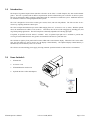
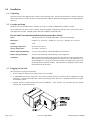
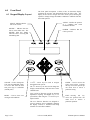
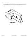
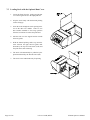
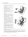
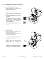
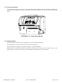
Installation and Operator’s Manual
© 2006
Unimark Products, LLC.
a Microcom Corporation Company
P/N: 71U-1415-100K, REV E
www.unimark.com
Unimark Service: USA #: (800) 255-6356 or (913) 649-2424
Table Of Contents
1.0
2.0
3.0
4.0
5.0
6.0
7.0
8.0
9.0
Introduction ----------------------------------------------------------------------------------------------Items Included -------------------------------------------------------------------------------------------Installation ------------------------------------------------------------------------------------------------3.1
Unpacking
3.2
Location and Setup
3.3
Plugging into the Unit
Host Interface Specifications -------------------------------------------------------------------------4.1
Hardware Interface
4.2
Data Structure
ASCII Control Character List -----------------------------------------------------------------------Front Panel -----------------------------------------------------------------------------------------------6.1
Keypad/Display Layout
6.2
Basic Operator Level Menu
6.3
Adjustments Menu
6.4
Service Menu
6.5
Selected Stock Type Parameters Setup Menu (Service Sub Menu)
6.6
Host Setup Menu (Service Sub Menu)
6.7
Comm Port Setup Menu (Service Sub Menu)
6.8
TCP/IP Setup Menu (Service Sub Menu)
6.9
ATB Setup Menu (Service Sub Menu)
6.10 Printer Setup Menu (Service Sub Menu)
6.11 Maintenance Menu (Service Sub Menu)
6.12 Printer Information (Service Sub Menu)
Loading Stock -------------------------------------------------------------------------------------------7.1
Adjusting the Input Path Size
7.2
Locking Down the Input Path
7.3
Loading Fan-Fold Stock
7.4
Loading Roll Stock
7.5
Loading Stock with the Optional Dust Cover
7.6
Clearing Stock Jams
Thermal Print Head, Platen, and Sensors ---------------------------------------------------------8.1
Cleaning the Thermal Print Head
8.2
Cleaning the Platen
8.3
Replacing the Thermal Print Head
8.4
Cleaning/Clearing the Present Sensor (PS)
8.5
Cleaning/Clearing the Left Top Of Form Sensor (TOF)
8.6
Cleaning/Clearing the Center Top Of Form Sensor (TOF)
Stock Cutter ----------------------------------------------------------------------------------------------9.1
Cutter Location
9.2
Cutter Operation
9.3
Clearing a Jam
ET6000 Operator’s Manual
71U-1415-100K; REV E
Page 4
Page 4
Page 5
Page 6
Page 6
Page 7
Page 22
Page 27
Page 31
Page 2 of 38
10.0
11.0
12.0
13.0
Troubleshooting ----------------------------------------------------------------------------------------10.1 Basic Failure Analysis
10.2 Basic Alert Messages
Models/Options -----------------------------------------------------------------------------------------11.1 L-Shaped Base Model
11.2 Roll Stock Model
11.3 Roll Stock Dust Cover Model
11.4 Path Dust Cover Model
11.5 Stock Cutter Model
11.6 Display Options
Customer/Technical Support ------------------------------------------------------------------------12.1 Return Authorization/Customer Service
12.2 Technical Support
Unimark Products, LLC. Warranty Statement ---------------------------------------------------
Page 32
Page 34
Page 37
Page 38
FCC Emission Interference
This device complies with Part 15 of the FCC Rules. Operation is subject to the
following two conditions:
(1)
This device may not cause harmful interference, and
(2)
This device must accept any interference received, including interference that
may cause undesired operation.
Any changes or modifications not expressly approved by Unimark could void the
operator’s authority to operate the equipment under these conditions and rules.
Note: This equipment has been tested and found to comply with the limits for a
Class A digital device, pursuant to part 15 of the FCC Rules. These limits
are designed to provide reasonable protection against harmful interference
when the equipment is operated in a commercial environment. This
equipment generates, uses, and can radiate radio frequency energy and, if not
installed and used in accordance with the instruction manual, may cause
harmful interference to radio communications. Operation of this equipment
in a residential area is likely to cause harmful interference in which case the
user will be required to correct the interference at their own cost.
Page 3 of 38
71U-1415-100K; REV E
ET6000 Operator’s Manual
1.0
Introduction:
The Express Tag 6000 Compact Printer (hereafter referred to as the Unit) is a small footprint, fast, and versatile thermal
printer. The Unit is provided with an RS-232 Asynchronous Serial Communication port to interface to the host system.
The port is configured as DTE, requiring a null-modem cable for connection to a DTE host system. Additional interfaces
are available to connect to existing and planned host systems.
The Unit is designed to fit into ticket counter, gate counter, kiosk, and curb side podiums. The Unit can also sit on a
counter top, requiring minimum counter space.
The Unit’s transport mechanism accepts stock widths ranging from 1.87” (4.74cm) to 3.62” (9.19cm). With the optional
cutter, the maximum stock width is 3.50” (8.89cm). This allows the Unit to be used in baggage tag, boarding pass, and
cargo label printing applications. The Unit incorporates a manually adjustable self-centering input path.
If required, an optional roll stock mount is available. Also, an optional input path case is available to provide dust
covering for stock behind the stock entry point in environments where dust is a particular issue.
The Unit has an eight key front panel with four status LEDs and a 2x20 character display. When the Unit is in the online
state, the front panel keys can be used to vary the display contrast/intensity. The adjusted display contrast/intensity is
automatically saved to memory after a few seconds.
The Unit uses an autoswitching power supply, allowing automatic operation in both 110 and 220 VAC environments.
2.0
Items Included:
1.
ET6000 Unit.
2.
AC Power Cord.
3.
ET6000 Manual or Product CD.
4.
Optional Interface Cables and Adaptors.
ET6000 Operator’s Manual
71U-1415-100K; REV E
Page 4 of 38
3.0
3.1
Installation
Unpacking
Open the top side of the shipping carton. Remove the top packing foam. Lift the Unit from the box, ensuring a firm grip
on the main enclosure. Remove the power cord and Operator’s Manual. Retain original shipping carton and packaging for
future use.
3.2
Location and Setup
Install the Unit on a flat stable surface. This may be on top of or inside a standard airline podium or counter.
Do not install the Unit where it will be directly exposed to sunlight. Sunlight will affect the Unit’s optical sensors at the
stock input and exit points. Sunlight will also affect the readability of the front panel.
Physical and Environmental Installation Requirements (Base Model)
3.3
Power:
100-120/200-240 VAC, 50/60Hz Single Phase. Three wire ground plug.
Dimensions:
Length: 16.75” (42.55cm) / Width: 8.63” (21.91cm) / Height: 6.50” (16.51cm)
Weight:
15 lbs
Operating Temperature:
40 to 104°F (4 to 40°C)
Storage Temperature:
-4 to 140°F (-20 to 60°C)
Relative Operating Humidity:
5 to 95%, non-condensing, without degradation of performance
Relative Storage Humidity:
5 to 95%, non-condensing, without damage to any components
Ventilation:
Make sure that the ventilation fan input is kept clear and free of foreign obstructions.
The fan input is located in the input path area so that the Unit can be installed in a very
enclosed (tight) area. As long as the stock area and the stock output point is kept clear,
the internal fan will function normally. The Unit has been designed so that the stock
itself cannot block the fan input.
Plugging into the Unit
The Unit requires two physical connections.
1. An IEC 320 power connection accepting 110/220 VAC (50/60Hz).
2.
A standard RS-232 interface connection. The Unit has a DB-25 female pin connector and is configured as a DTE
connection. A simple null-modem cable connection quickly interfaces the Unit to a standard connection on a typical
PC-based host system.
3.
Optional interfaces include parallel, dual serial, and Ethernet. These interfaces are accessible from the optional
interface plate location shown below.
Page 5 of 38
71U-1415-100K; REV E
ET6000 Operator’s Manual
4.0
4.1
Host Interface Specifications
Hardware Interface
The Unit base configuration uses an RS-232 Asynchronous Serial Communications port to interface to the Host system.
The physical connection is provided using a single DB-25 female pin connector. A simple null-modem cable connection
quickly interfaces the Unit to a standard connection on a typical PC-based host system. The pinout below provides the
basic cabling requirements to connect the Unit to a PC-type host system.
Pin number
Function
Source
1
2
3
4
5
6
7
11
20
8, 9, 10, 12, 13, 14, 15, 16, 17, 18, 19,
21, 22, 23, 24, 25
Earth Ground (shield)
Transmit Data (TxD)
Receive Data (RxD)
Request To Send (RTS)
Clear To Send (CTS)
Data Set Ready (DSR)
Signal Ground
Jumper to RTS
Data Terminal Ready (DTR)
No connect
n/a
Printer
Host
Printer
Host
Host
n/a
Printer
Printer
n/a
The connection from pin 11 to RTS enables the Unit to function with existing customer cabling. This connection can be
removed if necessary.
The Unit may also have optional hardware interfaces including parallel, dual serial, and Ethernet. Custom firmware
interfaces will be written for these and the existing serial interface.
4.2
Data Structure
The serial communications port uses an asynchronous serial data transmission method. Data is transmitted and received
based on a combination of the following possible communication parameters:
5.0
Baud
Data Length
Parity
Stop Bit
1200 - 115,200
7, 8
None, Even, Odd, Mark, Space
1, 2
ASCII Control Character List (some characters available with certain firmware versions only)
ACK
-
Acknowledge character (06HEX).
CR
-
Carriage Return character (0DHEX).
DC1
-
XON character (11HEX). Used to indicate that the host serial port is ready.
DC3
-
XOFF character (13HEX). Used to indicate that the host serial port is NOT ready.
ETX
-
End Of Text sequence. Used to suffix data and commands being sent to and received from the Unit.
LF
-
Line Feed character (0AHEX).
NAK
-
Negative Acknowledge character (15HEX).
SOH
-
Start Of Header character (01HEX). Sometimes used to prefix special commands or messages.
STX
-
Start Of Text sequence. Used to prefix data and commands being sent to and received from the Unit.
ET6000 Operator’s Manual
71U-1415-100K; REV E
Page 6 of 38
6.0
Front Panel
6.1 Keypad/Display Layout
The front panel incorporates a 2X20 (2 line, 20 character) display
providing the operator with information about the Unit’s state. The
display is also used to navigate the Unit’s menu system, allowing the
operator to change settings and address conditions to which the Unit has
alerted the operator.
ALERT - Notifies the operator
of a condition that needs
immediate attention.
STOCK - Indicates that the
Unit is out of stock.
ONLINE - Indicates that the
Unit is in the online state. The
ONLINE LED also flashes
when the Unit is receiving and
transmitting data.
ONLINE - Used to change the
Unit state from ONLINE (ready
to receive data from the host
and print tags) to OFFLINE
(standby state).
RESET - Used to clear error
messages and conditions.
POWER - Indicates that the
Unit is powered.
⇐⇒⇑⇓ - Arrow keys are used to navigate
through the menu system.
The ⇑ ⇓ arrow keys are also used to change the
display contrast/intensity while the Unit is in the
ONLINE state.
New versions of firmware provide an alternate
adjustment requiring the RESET key to be
pressed first, then using the ⇑ ⇓ arrow keys to
adjust contrast.
The new firmware function was designed to
prevent operators from accidentally changing
the display contrast to minimum and being
mistaken for a unit fault condition.
Page 7 of 38
71U-1415-100K; REV E
ENTER - Used to access the
Unit’s menu system. Pressing
this key moves the operator up
one menu level or selects a
particular setting.
EXIT - Pressing
this
key
moves the operator back one
menu level or cancels a
particular operation.
ET6000 Operator’s Manual
6.2 Basic Operator Level Menu
Menu structure may change depending on the specific customer firmware version.
Print Configuration
Print Sample
Test Pattern
Print Tests
Online/Offline (1)
Print Head Profile (3)
Adjustments (4)
Bag Tag (6)
Cargo Tag (6)
Select Doc Type (5)
Board Pass / ATB Cards (6)
Service Menu (7)
Onion Skin (6)
Notes:
1.
Press Online then Enter for menu access. Enter moves user up into the menu or accepts a value or selection. Exit backs the
user out of the menu.
2.
An asterisk (*) appears next to the currently selected parameter.
3.
Print head Profile performs a profile and prints results. Note that print head profile algorithm takes approximately 20
seconds.
4.
See adjustments sub menu tree for further details.
5.
Allows the operator to select different stock type formats (Bag Tag, Boarding Pass, Cargo Tag are standard Unimark
defaults).
6.
Shows some possible default document types provided by Unimark. Not available on all versions. Others may be added by
the customer through the service menu or provided by Unimark from the factory per customer definition.
7.
Service menu is password protected.
ET6000 Operator’s Manual
71U-1415-100K; REV E
Page 8 of 38
6.3 Adjustments Menu
Menu structure may change depending on the specific customer firmware version.
Left Margin (dots) (1)
Enter Value
Top Margin (dots) (2)
Enter Value
Contrast (3)
Enter Value
2 Inches Per Second
3 Inches Per Second
4 Inches Per Second
Adjustments
Print Speed (4)
5 Inches Per Second
6 Inches Per Second
7 Inches Per Second
8 Inches Per Second
Normal
Print Direction (5)
Reverse
Print Sample
Notes: The following adjustments affect only the currently selected Document Type and can be set differently for each
Document Type.
Also note that all of these parameters are duplicated in the “Selected Type” Setup menu shown on page 4 and changing
these parameters in either menu affects the corresponding parameter in the other menu.
1.
Left Margin shifts the entire printed image to the right (larger values) or to the left (lesser values).
2.
Top Margin shifts the entire printed image to the top (larger values) or to the bottom (lesser values).
3.
Contrast selects print darkness (higher numbers create darker print). Note that higher contrast settings can decrease print
quality on sensitive stock. Please choose the best, not necessarily highest, value for each Document Type.
4.
Print Speed selects the print speed. Note that some, less sensitive stocks may need to use lower print speed to achieve
acceptable print quality.
Not all versions have the full ranges of speed selections showed here.
5.
Print Direction adjusts for whether stock is loaded into the ET6000 leading or trailing edge first. This parameter
effectively rotates the print image 180 degrees.
Page 9 of 38
71U-1415-100K; REV E
ET6000 Operator’s Manual
6.4 Service Menu
Menu structure may change depending on the specific customer firmware version.
"Selected Doc Type" Setup (4)
Host Setup
Comm Port Setup
TCP/IP Setup (1)
Service Menu (3)
ATB Setup (2)
Printer Setup
Maintenance
Printer Information
Notes:
1. Service/Ethernet (Network Login, TCP/IP) selections are only available when the optional Ethernet Communications option
is installed.
Other menus for options like USB may be available depending on the firmware and hardware configuration.
2.
3.
4.
ATB menu available when Board Pass or ATB type stock is selected.
Service menu is password protected and may vary depending on the customer.
Selected Doc Type is the document type that has been selected by the operator and is currently active.
ET6000 Operator’s Manual
71U-1415-100K; REV E
Page 10 of 38
6.5 Selected Stock Type Parameters Setup Menu (Service sub menu)
Menu structure may change depending on the specific customer firmware version.
Tag Length
Enter Value
Normal
Stock Type
Receipt
Normal
Tag Width
Enter Value
Print Direction
Reverse
None
Left Margin
Enter Value
Labels
(Backing)
"Selected Doc
Type" Setup
Top Of Form Mode
Tickets
(Hole)
Top Margin
Contrast
Enter Value
See TOF Setup
Menu detail on next
page
Black
Mark
Tear Off Position
Adjust
Enter
Value
Enter
Value
Enter Value
Print Speed
2-8 IPS
Vertical Position
Adjust
Ladder BC
Print Speed
2-8 IPS
Print Sample
Not all firmware versions support the options listed, such as print speed range and ladder speed.
Page 11 of 38
71U-1415-100K; REV E
ET6000 Operator’s Manual
6.6 Host Setup Menu (Service sub menu)
Menu structure may change depending on the specific customer firmware version.
STX Sequence
Enter Value
Rcv STX Sequence
Enter Value
ETX Sequence
Enter Value
Rcv ETX Sequence
Enter Value
ALT STX Sequence
Enter Value
Trans STX Sequence
Enter Value
ALT ETX Sequence
Enter Value
Trans ETX Sequence
Enter Value
Transaction Code
Enter Value
Rcv ETB Sequence
Enter Value
Intermediate PROK
Select Y/N
Trans ETB Sequence
Enter Value
Host Setup
STX/ETX
COMM Protocol
ACK/NAK
"Custom"
Strip LF/CR
Select Y/N
Notes:
1.
Rcv STX / ETX Sequence and Trans STX / ETX Sequences allow the operator to select the various Start of Transmission
(STX) and End of Transmission (ETX) characters to receive and transmit messages to and from the host. The Unit looks for
the specified Rcv STX (or ALT STX in some versions) for incoming data, and once received, looks for the Rcv ETX to signal
the end of a data transmission. The Unit sends the Trans STX (if different than the Rcv STX) at the beginning of all messages
sent to the host and appends the Trans ETX (if different than the Rcv ETX) at the end of all messages sent to the host. Each
sequence can be up to three characters. Enter the value of each character in Hex notation (base 16).
To use less than three characters set the unused trailing characters to zero. Setting all three characters to zero disables the
particular sequence. In this case the Unit will ignore start and/or end of transmission characters for incoming data and will not
append start and/or end of transmission characters to outgoing data. A receive ETX of 00 00 00 is not allowed, and must be at
least one character for the unit to properly receive messages.
2.
Rcv ETB Sequence and Trans ETB Sequence select the various End of Block (ETB) characters to receive and transmit
messages to and from the host. This selection is typically used with ACK/NAK protocol. The Unit looks for the specified Rcv
ETB to identify the end of the blocks in the incoming data. The Unit sends the Trans ETB at the end of the blocks of data sent
to the host. The exact format that the ETB is used varies for each protocol selected and specific customer requirements. Enter
the value of each character in Hex notation (base 16).
3.
COMM Protocol allows the operator to select different communication formats for data transfer to and from the host system.
The most commonly used formats are STX/ETX and ACK/NAK (custom protocols provided as required).
4.
Strip Line Feed and/or Carriage Return options allow the Unit to remove LF and CR characters from the received data stream.
This is usually a very custom type option or feature, and may vary or be enhanced to look at other data sequences depending on
the customer’s requirements.
ET6000 Operator’s Manual
71U-1415-100K; REV E
Page 12 of 38
6.7 Comm Port Setup Menu (Service sub menu)
Menu structure may change depending on the specific customer firmware version.
RTS/CTS
1200
2400
DSR/DTR
Printer Busy
XON/XOFF
4800
NONE
9600
Baud Rate
RTS/CTS
19200
38400
DSR/DTR
Printer Online
57600
XON/XOFF
115200
NONE
Comm Port Setup
RTS/CTS
None
Even
Parity
DSR/DTR
Host Busy
XON/XOFF
Odd
NONE
Mark
Space
7
Data Bits
RTS/CTS
DSR/DTR
Host Online
XON/XOFF
8
NONE
1
Stop Bits
2
Page 13 of 38
71U-1415-100K; REV E
Pacing Chars
Enter Value
Pacing Time
Enter Value
ET6000 Operator’s Manual
Notes:
1.
Baud Rate selects the baud rate for the serial port from the available choices.
2.
Parity selects the parity type to check received data and add to transmitted for the serial port.
• None does not add a parity bit to outgoing data and does not expect a parity bit for incoming data.
• Even generates a comm error if each incoming data byte does not have an even number of one bits and sets the parity bit on
outgoing data so each byte has an even number of one bits.
• Odd is the same as Even, except an odd number of one bits is used.
• Mark always sets the parity bit on out going data to a "mark" and generates a comm error if the parity bit in incoming data is
not a "mark".
• Space is the same as "mark" except "space" is used.
3.
Data Bits selects the number of data bits for each character transmitted, exclusive of parity, start and stop bits.
4.
Stop Bits selects the number of stop bits appended to out going data and allowed for in incoming data.
5. Printer Busy selects flow control method for data from the host to the Unit.
• None allows data to flow to the Unit whenever the host needs to. If the host sends large amounts of data to the Unit without
flow control, data may be lost.
• Selecting XON/XOFF provides software flow control. The Unit sends an XOFF character to the host to stop data
transmission and an XON character when it is ready to receive data. Software flow control is only recommended at lower
baud rates.
• Selecting RTS/CTS configures the Unit to deactivate its RTS output (pin 4) when it is busy and cannot receive data. Select
this option if the host monitors its CTS input for flow control.
• Selecting DSR/DTR configures the Unit to deactivate its DTR output (pin 20) when it is busy and cannot receive data. Select
this option if the host monitors its DSR input for flow control.
6.
Printer Online selects the control method to inform the host that the printer is powered on and ready to process data.
• None disables the Unit from signaling the host whether it is online or offline.
• Selecting XON/XOFF provides software flow control. The Unit sends an XOFF character to the host to indicate it is offline
and an XON character when it is online. Software flow control is only recommended at lower baud rates.
• Selecting RTS/CTS configures the Unit to deactivate its RTS output (pin 4) when it is offline. This signal is typically
connected to a CTS input on the host. Select this option if the host monitors its CTS input for to determine printer status.
• Selecting DSR/DSR/DTR configures the Unit to deactivate its DTR output (pin 20) when it is offline. This signal is typically
connected to a DSR input on the host. Select this option if the host monitors its DSR input for to determine printer status.
7.
Host Busy selects flow control method for data from the Unit to the host.
• None allows data to flow to host whenever the Unit needs to send it. If the Unit sends large amounts of data to host without
flow control, data may be lost.
• Selecting XON/XOFF provides software flow control. The Unit stops sending data to the host when an XOFF character is
received and resumes sending data to the host when an XON character is received. Software flow control is only
recommended at lower baud rates.
• Selecting RTS/CTS configures the Unit to stop sending data when its CTS input (pin 5), which is typically connected to a RTS
output on the host, is deactivated. Select this option if the host uses its RTS output for flow control.
• Selecting DSR/DTR configures the Unit to stop sending data when its DSR input (pin 6), which is typically connected to a
DTR output on the host, is deactivated. Select this option if the host uses its DTR output for flow control.
8.
Host Online selects the control method to inform the Unit that the host is powered on and ready to communicate.
• None disables the Unit from checking whether the host online or offline.
• Selecting XON/XOFF provide software flow control. The host sends an XOFF character to the Unit to indicate it is offline
and an XON character when it is online.
• Selecting RTS/CTS configures the Unit to monitor its CTS input (pin 5) to determine the host's status. This signal is
typically connected to a RTS output from the host. Select this option if the controls its RTS output to indicate status.
• Selecting DSR/DSR/DTR configures the Unit to monitor its DSR input (pin 6) to determine host status. This signal is
typically connected to a DTR output from the host. Select this option if the host controls its DTR output to indicate status.
9.
Pacing Char determines the number of characters transmitted to the host when the pacing time (timeout) has run out.
10. Pacing Time determines the timeout period before the unit transmits the next set of pacing characters to the host.Host Online
selects the control method to inform the Unit that the host is powered on and ready to communicate.
ET6000 Operator’s Manual
71U-1415-100K; REV E
Page 14 of 38
6.8 TCP/IP Setup Menu (Service sub menu)
Menu structure may change depending on the specific customer firmware version.
TCP/IP Setup
Get Dynamic IP Addr
Select Y/N
Printer IP Address
Enter Value
Gateway
Enter Value
Subnet Mask
Enter Value
Primary DNS
Enter Value
Secondary DNS
Enter Value
View Registered DNS
Page 15 of 38
DNS Server 1
Display
Value
DNS Server 2
Display
Value
DNS Server 3
Display
Value
Host TCP Port
Enter Value
MAC Address
Display Value
71U-1415-100K; REV E
ET6000 Operator’s Manual
Notes:
1.
Get Dynamic IP Addr , when enabled, allows the Unit to lease an IP address from a DHCP server, otherwise the IP address is
entered via the Printer IP Address menu. Note that a DHCP server must be available and accessible on the network for this
feature to be enabled, otherwise, the printer may not be able to communicate via its Ethernet interface. Also note that the Unit
needs to reboot when enabling or disabling this feature or when changing IP address, gateway or subnet mask, and requires a key
be pressed on the front panel to complete.
2.
Printer IP Address either shows the IP address obtained from the DHCP server if Get Dynamic IP Address is enabled, otherwise
the printer IP address can be entered into this menu.
3.
Gateway either shows the Gateway IP address obtained from the DHCP server if Get Dynamic IP Address is enabled, otherwise
the Gateway IP address can be entered into this menu. Note that the Gateway IP address is only relevant on larger networks
where routers are in use. The Unit uses the Gateway IP Address to send Ethernet packets that it determines belong to hosts not
located on the local segment.
4.
Subnet Mask either shows the Subnet Mask obtained from the DHCP server if Get Dynamic IP Address is enabled, otherwise the
Subnet Mask can be entered into this menu. Note that the Subnet Mask is only relevant on larger networks where routers are in
use. The Unit uses the Subnet Mask to determine when to address an Ethernet packet to the Gateway for hosts not on the local
segment.
Note: incorrect setup of either the Gateway IP Address or Subnet Mask may result in the inability for the Unit to correctly
communicate using its Ethernet interface.
5.
Primary DNS, Secondary DNS allows the user to specify the IP Addresses of up to two DNS servers to query when resolving
DNS names to IP addresses. The primary DNS server is queried first followed by the secondary DNS server if the primary does
not return a result.
6.
View Registered DNS, DNS Server 1, DNS Server 2, DNS Server 3 are only accessible if Get Dynamic IP Address is enabled.
When enabled, the Unit will obtain up to three DNS server IP addresses from the DHCP server. These DNS server IP addresses
can be viewed in these menus.
Note that the Unit can query a total of three DNS servers when attempting to resolve a DNS name. The Unit first queries the
DNS server IP addresses assigned by the DHCP server, in order of DNS server 1 then 2 then 3. If less then three are assigned,
then the Unit will next query the DNS servers entered into the Primary and Secondary DNS server menu items.
7.
Host TCP Port allows the port address value to be set by the operator.
8.
MAC Address This is a display only of the MAC Address assigned by Unimark to the Ethernet adapter installed in this Unit.
The MAC address is also known as the Ethernet address, hardware address, node address, IEEE address, OUI, and others. It is
a 48 bit number unique to each Ethernet adapter.
ET6000 Operator’s Manual
71U-1415-100K; REV E
Page 16 of 38
6.9 ATB Setup Menu (Service sub menu)
Menu structure may change depending on the specific customer firmware version.
Type 0, Reserved
Type 1, ATB
Type 2, MPD
Type 3, BP
Type 4, Blank
Stock Type
Type 5, BSP ARC
Type 6, Reserved
Type 7, Reserved
Type 8, Reserved
Type 9, Reserved
ATB Setup
Error on Stock Type
Select Y/N
Error on Missing Logo
Select Y/N
Template X Adjust
Enter Value
Template Y Adjust
Enter Value
No Mode Changes
AEA Mode
Check-In
Ticketing
BT Cmd Sets Length
Select Y/N
Notes:
1. AEA Mode allows the operator to select between Check-In and Ticketing modes. The third option is “No Mode Changes” and
is used to modify some AEA responses when they need to be different from their regular response when in either of the two
normal modes.
2. Error on Stock Type allows the operator to enable or disable the error checking function that verifies the stock type selected in
the ticketing data stream match the stock types selected for each bin in the menu.
3. Error on Missing Logo allows the operator to enable or disable the error checking function that verifies that the logo called out
in the ticketing data stream is properly loaded in memory.
4. Template X,Y adjust moves templates left/right or up/down to allow alignment of the templates to AEA row/column
coordinates.
5. BT CMD Sets Length is provided for backwards compatibility. Prior to AEA 95’ the BT command selected stock type but
not length.
Page 17 of 38
71U-1415-100K; REV E
ET6000 Operator’s Manual
6.10 Printer Setup Menu (Service sub menu)
Menu structure may change depending on the specific customer firmware version.
Dot Out Warn
Level
Enter Value
Edit "Type 1"
Enter/Change
Description
Bar Code Shift
Enable
Select Y/N
Edit "Type 2"
Enter/Change
Description
Edit "Type 3"
Enter/Change
Description
Edit "Type 4"
Enter/Change
Description
Add Doc
Type
Select from BT,
Cargo, or BP
Delete Doc
Type
Select existing
Type to Delete
Select Doc
Type
Select Active
Type
Never
Wait Prev Tag
Taken
First Tag Only
Every Tag
Printer
Setup
Change Doc Types
Change
Password
Enter Value
Password
Enable
Select Y/N
Disp Contrast
Adj
Select Disabled,
Arrow Keys, or
Reset + Arrow Keys
Notes:
1. Dot Out Warn Level sets the threshold where the ET6000 issues a replace print head message. Some versions incorporate
two menus that allow setting a total dot level and total adjacent dot level threshold.
2. Bar Code Shift Enable causes the ET6000 to attempt to shift a bar code to either side to compensate for missing dots. If a
position cannot be found where only good dots exist, the ET6000 will not print the barcode unless a specific customer
requirement overrides this function. In which case the barcode would be printed in the location defined by the PECTAB.
3. Wait Prev Tag Taken causes the ET6000 to wait for each tag to be removed prior to printing the next tag (Every Tag
setting) or wait for the previously printed tags of a group to be removed prior to printing the new group (First Tag Only
setting) or print each tag as it is processed (Never setting). Menu is sometimes located in individual stock menus so the
parameter can be set per the document stock type.
4. Change Password allows the Service Password to be changed. This password is required to access Service Menu items.
5. Enable Password; When set to Disabled, the operator has unrestricted access to the Service Menu. When enabled, the
operator is required to enter the Service Password for access.
6. Disp Contrast Adj. allows the operator to adjust the LCD contrast. When set to Arrow keys, the operator uses the Up/Down
arrow keys to adjust the LCD contrast. When set to Reset + Arrow keys, the operator must first press and hold the Reset
key then use the Up/Down arrow keys to adjust the LCD contrast. In both cases the unit must be in the Online state. LCD
contrast adjustments may be required when the Unit is moved between environments with radically different temperatures.
Older versions of firmware only allow for Enable/Disable settings, and Arrow keys alone are used to adjust LCD contrast.
7. Change Doc Types allows the user to rename the various document type names (Edit BAG TAG, Edit CARGO TAG, Edit
BOARD PASS, Edit ATB Cards, Edit Onion Skin) so these, or added document types can be renamed in the menus. Add
Doc Type adds a new document type to the menu. The parameters of the added document type will be given defaults based
on the type of document selected. The Delete Doc Type allows the specified document type to be deleted from the ET6000.
ET6000 Operator’s Manual
71U-1415-100K; REV E
Page 18 of 38
6.11 Maintenance Menu (Service sub menu)
Menu structure may change depending on the specific customer firmware version.
Test Motor
Test Cutter
TOF Sensor View
Display Value
Exit Sensor View
Display Value
Head Up Sw itch View
Display Value
PH Temp/Voltage View
Display Value
Auto Sensor Set
Follow Inst on Display
TOF Sensor Setup
Enter Tag Length
Sensor View
Test Display
New Printhead
Printhead Profile
Maintenance
Form Feed
Print Continuous
Sensor Setup
Page 19 of 38
Exit Sensor View
Display Value
Exit Paper Detect
Enter Value
Exit Sensor Drive
Enter Value
TOF Sensor View
Display Value
TOF Paper Detect
Enter Value
TOF Drive Level
Enter Value
TOF Back Sensitivity
Enter Value
TOF Back Drive Level
Enter Value
Erase AEA Flash
Confirm Operation
Test NetArm Comm
Display Results
71U-1415-100K; REV E
ET6000 Operator’s Manual
Notes:
1.
Test Motor runs the platen motor for a short time. User is prompted to lift the print head during test.
2.
Test Cutter cycles the cutter blade once and returns it to the home position.
3.
TOF Sensor View shows the numeric value read from the TOF Sensor. Loading and unloading stock should cause the
number to vary widely indicating that the sensor is functional. It is normal for this value to fluctuate slightly even when
stock is not being loaded or unloaded.
4.
Exit Sensor View shows the numeric value read from the Exit Sensor. Passing stock over the Exit Sensor should cause the
number to vary widely indicating that the sensor is functional. It is normal for this value to fluctuate slightly even when
stock is not being passed across the sensor.
5.
Head Up Sw. View shows the value read from the head position switch. Opening and closing the print head latch should
cause this value to display whether the head is up or down.
6.
Temp/Voltage View shows the print head substrate temperature and output voltage of the 24 volt supply. The print head
temperature may increase after printing a large number of tags, otherwise it should be close to room temperature. If the
print head temperature reaches 60 degrees C., the ET6000 indicates a temperature fault and disables printing until the print
head cools down. The voltage reading from the 24 volt supply is approximately 24 volts and can vary depending on the
load of the power supply. If this voltage exceeds 25 volts, the ET6000 indicates an overvoltage fault and disables printing
until the voltage is back in the acceptable range. It is normal for some fluctuation of these readings, even when the printer
is idle.
7.
Test Display turns on all dots on the LCD display and all the LEDs. Press any key to exit this test.
8.
New Prrinthead must be selected whenever a new print head is installed into the ET6000. Selecting this option causes
several actions: all print head specific counters are zeroed and a new print head baseline resistance is measured and stored.
It is important to select this item whenever, and only when, a new print head is installed so a correct baseline resistance is
used in the print head power management and when setting the criteria to detect bad dots. Failure to do so can lead to
premature print head failure or poor print quality.
9.
Prnhd Profile causes the ET6000 to measure the current resistance value of each of the 640 print head dot elements. The
result is printed on a graph along with baseline resistance, high and low resistance tolerance markings. Note that the
profile takes about 20 seconds to perform.
10.
Sensor Setup menu is identical to the "Selected Stock Type" TOF Setup menu except with the addition of the Auto Sensor
Set item. Any TOF sensor settings made in this menu via the sensor calibration procedure are used globally when a new
stock type is created (copies from the maintenance menu settings). No TOF calibrations made under the maintenance
menu will affect the TOF operation of any of the stock types (these must be made under the specific stock type menu).
The Auto Sensor Set option calculates the TOF level without any stock loaded and calibrates the Exit sensor. These
calculations affect Unit operation globally, not matter what stock type is selected.
11.
Erase AEA Flash causes the AEA memory that stores downloaded PECTABs, logos, and templates to be erased. This
option is required if the memory becomes corrupted for some reason. It should not be used otherwise because all objects
in this memory will be permanently erased. Resident fonts and logos are not affected.
12.
Test NetArm Communications tests PCBA comm.. Only available if the optional is installed.
ET6000 Operator’s Manual
71U-1415-100K; REV E
Page 20 of 38
6.12 Printer Information Menu (Service sub menu)
Menu structure may change depending on the specific customer firmware version.
Service Stock
Display Value
Service Jams
Display Value
Service Power On
Display Value
Printhead Stock
Display Value
Serial Number
Display Value
Boot Block
Display Value
Application
Display Value
Ethernet
Display Value
Counters
Printer
Information
Versions & S/N
Notes:
1. Counters menu displays the various information counts on the LCD display:
2. Service Stock is the amount of stock printed (in cm) for the ET6000 since the last time the ET6000 was serviced by Unimark
3. Service Jams is the number of jams for the ET6000 since the last time the ET6000 was serviced by Unimark
4. Service Power is the number of power on hours for the ET6000 since the last time the ET6000 was serviced by Unimark.
5. Print head Stock is the amount of stock printed (in cm) for the installed print head, assuming the new print head menu was
activated when the print head was installed.
6. Versions & S/N provides information about the firmware version and printer serial number. Every ET6000 has a Boot Block and
Application firmware installed. Only ET6000s with the Ethernet Adapter option display an Ethernet version number.
Page 21 of 38
71U-1415-100K; REV E
ET6000 Operator’s Manual
7.0
7.1
Loading Stock
Adjusting the Input Path Size
The Unit is equipped with a simple input path adjustment method. To adjust the input path, follow these steps:
7.2
1.
Turn the Unit off, and verify that the print head is fully latched down.
2.
Grip the adjustment paddle and adjust the width so that it is close to the actual stock width (move the guides by
holding the left guide straight and moving it right or left to widen or narrow the input path).
3.
Insert stock until it comes in contact with the print head/platen (do not force/crumple stock).
4.
Make any final adjustments to the input path so that it is as close to the stock width as possible. The input path should
be no larger than 0.01” (2.54mm) of the stock width. Note that stock width can vary from box to box.
5.
Pull stock in and out a few times to check stock movement within the path. The input path adjustment is self
centering, therefore no other positioning adjustments are required.
Locking Down the Input Path
The Unit is equipped with a lock-down thumbscrew to secure the path guides. To secure the guides, follow these steps:
1.
Follow steps 1-4 in section 7.1 above.
2.
While holding the adjustment paddle and ensuring guides are against the installed stock, turn the lock-down screw
clockwise until it bottoms out against the rail. Verify stock movement through the path after the thumbscrew is
secured.
To use a different width stock, turn the lock-down screw counterclockwise to loosen the rails. Retighten the screw
once the correct width is determined.
3.
The thumbscrew is aligned with a securing pad to help keep the screw from slipping. If the pad is removed, there will
be two threaded hole positions (depending on the vintage of the Unit).
3.1
Position one provides a stationary path approximately 3.25” (82.55mm) wide for ATB type stocks.
3.2
Position two provides a stationary path approximately 2.00” (50.8mm) wide for bag tag type stocks.
ET6000 Operator’s Manual
71U-1415-100K; REV E
Page 22 of 38
7.3
Loading Fan-Fold Stock
1.
Grip the stock firmly with the thermal printing surface facing up.
2.
With the thermal printing surface up, insert the stock between the right and left guide until detected by the Top Of
Form sensor (TOF) and the print motor starts advancing.
3.
The stock will automatically be pulled in by the platen and detected by the Present Sensor (PS).
4.
The stock is now loaded and ready for printing.
Page 23 of 38
71U-1415-100K; REV E
ET6000 Operator’s Manual
7.4
Loading Roll Stock
1.
Pull the outer roll stock alignment guide down
towards the outside of the Unit.
2.
Place the roll onto the support arm.
3.
Lift the outer roll stock guide to its upright
position.
4.
Center the roll using the support/alignment
guides. Reference the alignment marks on the
back or front side of the roll stock support arm.
5.
With the thermal printing surface up, insert the
stock between the right and left guide until
detected by the Top Of Form sensor (TOF) and
the print motor starts advancing.
6.
The stock will automatically be pulled in by the
platen and detected by the Present Sensor (PS).
7.
The stock is now loaded and ready for printing.
Outer Roll Stock
Alignment Guide
Alignment
Marks
Thermal
printing
surface out
Wound Out Stock Roll Shown
ET6000 Operator’s Manual
71U-1415-100K; REV E
Page 24 of 38
7.5
Loading Stock with the Optional Dust Cover
1.
Locate the finger lift point. Swing open the dust
cover door to gain access to the input path area.
2.
Grip the stock firmly with the thermal printing
surface facing up.
3.
Insert the stock through the stock opening in the
rear of the dust cover module. There are two
dust brushes intended to clear large particles
from the stock before it reaches the print head.
4.
Pull the stock over the support bracket towards
the stock guides.
5.
With the thermal printing surface up, insert the
stock between the right and left guide until
detected by the Top Of Form sensor (TOF) and
the print motor starts advancing.
6.
The stock will automatically be pulled in by the
platen and detected by the Present Sensor (PS).
7.
The stock is now loaded and ready for printing.
Page 25 of 38
71U-1415-100K; REV E
ET6000 Operator’s Manual
7.6
Clearing Stock Jams
In the unlikely event that a stock jam occurs, use the following procedure to clear the jam and continue printing operations:
1.
Press the RESET button on the front panel. If
the jam does not clear by itself, proceed with the
following steps:
2. Power the Unit off. CAUTION: Print
Head is sensitive to ESD.
3.
Press the front panel release button. Lift the
front panel up and out of the way.
4.
Pull the print head release lever forward and lift
the print head up away from the platen.
5.
Grip the stock firmly from the rear of the Unit
and remove.
6.
Check the print head and platen for adhered
label stock.
7.
If there is label stock on the print head, use 99%
(or higher) isopropyl alcohol to clean the heater
element surface. Verify that all label stock,
media residue, and any other contaminants are
clear from the print head.
8.
If label stock is wrapped around the platen,
rotate the platen and find a loose end of the
stock. Grip the stock firmly and pull it free from
the platen.
DO NOT USE A SHARP BLADE TO
CUT STOCK FROM THE PLATEN.
9.
If label stock still remains on the platen, use 50%
(or lower) isopropyl alcohol to clean the platen
surface. Verify that all label stock, media
residue, and any other contaminants are clear
from the platen.
10. Although the stock guides are very short, check
both right and left sides for any label stock
which may have adhered to them. Use 99% (or
higher) isopropyl alcohol to clean these areas.
11. Verify that stock related contaminants are not
blocking the Top Of Form (TOF) sensor in the
left stock guide. Use canned air to clear sensor
if necessary.
12. Verify that stock related contaminants are not blocking the Present Sensor (PS) at the exit point of the Unit. Use
canned air to clear sensor if necessary.
13. Check the ESD static brush for any label stock and related contaminants. Carefully remove these contaminants.
DO NOT USE ALCOHOL OR OTHER CHEMICALS TO CLEAN ESD STATIC BRUSH.
If the brush is damaged, replace the brush and or Unit immediately. Operating the Unit without an ESD static
brush, or with a damaged brush, may result in reduced print head life.
ET6000 Operator’s Manual
71U-1415-100K; REV E
Page 26 of 38
8.0
8.1
Thermal Print Head, Platen, and Sensors
Cleaning the Thermal Print Head
1. Power the Unit off. CAUTION: Print
Head is sensitive to ESD.
2.
Press the front panel release button and lift the
front panel up and out of the way.
3.
Pull the print head release lever forward and lift
the print head up away from the platen.
4.
Grip the stock firmly from the rear of the Unit
and remove.
5.
Clean the print head heater element surface using
the print head cleaning pad (part of cleaning kit
P/N 700-5020-000). Verify that all label stock,
media residue, and any other contaminants are
cleared from the print head.
Unimark recommends cleaning the print head
every fifth box of stock or 100,000 inches of
printing.
8.2
Cleaning the Platen
1. Power the Unit off. CAUTION: Print
Head is sensitive to ESD.
2.
Press the front panel release button and lift the
front panel up and out of the way.
3.
Pull the print head release lever forward and lift
the print head up away from the platen.
4.
Grip the stock firmly from the rear of the Unit
and remove.
5.
Clean the Platen surface using the Platen
cleaning
pad
(part
of
cleaning
kit
P/N 700-5020-000). Verify that all label stock,
media residue, and any other contaminants are
cleared from the Platen.
Unimark recommends cleaning the Platen every
fifth box of stock or 100,000 inches of printing.
Page 27 of 38
71U-1415-100K; REV E
ET6000 Operator’s Manual
8.3
Replacing the Thermal Print Head
1.
While the suspect print head is still installed, print the print head profile and configuration coupons. Retain for return to
Unimark Products, LLC. with the suspect print head.
2. Power the Unit off. CAUTION: Print Head is sensitive to ESD.
3.
Press the front panel release
button. Lift the front panel up and
out of the way.
4.
Pull the print head release lever
forward and lift the print head up
away from the platen.
5.
Grip the stock firmly from the rear
of the Unit and remove.
6.
Place a coin into the tool slot in
the thumbscrew, and turn counter
clockwise to loosen.
7.
Once both thumbscrews have been loosened, pull the print
head away from the mounting plate. Remove the power and
interface cables from the print head assembly.
8.
Wrap the print head profile and configuration coupons around
the suspect print head assembly and secure in a bag for
shipment back to Unimark Products, LLC. for evaluation.
9.
Locate new print head assembly. Install the power and
interface cables into the print head assembly.
10. Using the two alignment pins to position the print head
assembly, place the print head assembly into the mounting
position, and tighten the two thumbscrews (turn clockwise to
secure). Unimark recommends torqing to 6in-lbs, and using
Loctite #222 to secure the thumbscrews.
11. Power the Unit on. Take the Unit offline by pressing the
ONLINE key.
12. Press the ENTER key and then either the UP or DOWN arrow
until the SERVICE MENU appears. Press the ENTER key.
Enter the service password (UP/DOWN arrows change the
individual character value and RIGHT/LEFT arrows move the
cursor side to side). Press the ENTER key.
13. Press the UP or DOWN arrow key until the MAINTENANCE
menu appears. Press the ENTER key.
14. Press the UP or DOWN arrow key until the NEW
PRINTHEAD option appears. Press the ENTER key. The
Unit will read the baseline resistance of the print head you just
installed. Once the baseline resistance has been read, press
the ONLINE key to put the Unit back into service.
ET6000 Operator’s Manual
71U-1415-100K; REV E
Page 28 of 38
8.4
8.5
Cleaning/Clearing the Present Sensor (PS)
1.
Press the front panel release button. Lift the
front panel up and out of the way.
2.
Pull the print head release lever forward and lift
the print head up away from the platen.
3.
Grip the stock firmly from the rear of the Unit
and remove.
4.
Clean the present sensor window and the sensor
reflector plate using a dry cloth. Verify they are
clear of particles, paper stock, and dust. Use
canned air to clear sensor.
Do not use alcohol except to clean off adhered
labels or adhesives.
Cleaning/Clearing the Left Top Of Form Sensor (TOF)
1.
Press the front panel release button. Lift the
front panel up and out of the way.
2.
Pull the print head release lever forward and lift
the print head up away from the platen.
3.
Grip the stock firmly from the rear of the Unit
and remove.
4.
Clean the top of form transmitter and receiver
using a dry cloth. Verify they are clear of
particles, paper stock, and dust. Use canned air
to clear sensor.
Do not use alcohol except to clean off adhered
labels or adhesives.
Page 29 of 38
71U-1415-100K; REV E
ET6000 Operator’s Manual
8.6
Cleaning/Clearing the Center Top Of Form Sensor (TOF)
1.
Press the front panel release button. Lift the
front panel up and out of the way.
2.
Pull the print head release lever forward and lift
the print head up away from the platen.
3.
Grip the stock firmly from the rear of the Unit
and remove.
4.
Clean the top of form transmitter and receiver
using a dry cloth. Verify they are clear of
particles, paper stock, and dust. Use canned air
to clear sensor.
Do not use alcohol except to clean off adhered
labels or adhesives.
ET6000 Operator’s Manual
71U-1415-100K; REV E
Page 30 of 38
9.0
9.1
Stock Cutter
Cutter Location
The cutter is located in the front of the Unit.
It is designed to cut between each stock piece
(approximately at the perforation point).
9.2
Cutter Operation
The cutter option is designed to cut between each
stock piece (approximately at the perforation point).
The Unit monitors the cutter and automatically
detects when the cut is made.
Perforation
Typical Cut Location
The stock is released at the time of the cut. The stock
position resets for the next print and cut cycle.
The cutter is set up through the front panel, and exact
operation will depend on customer requirements.
9.3
TOF Holes
Clearing a Jam
In the unlikely event that a stock jam occurs, use the
following procedure to clear the jam:
1. Power the Unit off. Unplug the AC
power cable from the Unit. CAUTION:
Print Head is sensitive to ESD.
2.
Press the front panel release button. Lift the
front panel up and out of the way.
3.
Pull the print head release lever forward and lift
the print head up away from the platen.
4.
Grip the stock firmly from the front of the Unit
and remove from the cutter.
5.
Grip the stock firmly from the rear of the Unit
and remove.
6.
Locate the blade location adjustment screw. Use
a flat blade screw driver and turn the adjustment
clockwise. Verify that the blade moves up and
down freely.
7.
If there is label stock on the blade, use 99% (or
higher) isopropyl alcohol to clean it. Verify that
all label stock, media residue, and any other
contaminants are clear from the cutter
mechanism.
Note that the cutter blade is sharp.
Page 31 of 38
71U-1415-100K; REV E
ET6000 Operator’s Manual
10.0 Troubleshooting
10.1 Basic Failure Analysis
The following section is provided to assist in the installation of the Unit and covers issues which may occur when
installing new equipment. This section is not intended for regular maintenance or repair of the Unit.
1. NO POWER (Unit will not power up)
a.
b.
Verify AC plug is installed into the rear of the Unit.
Check the AC line level. The Unit is designed to operate at voltages as low as 90 VAC.
2. NO COMMUNICATIONS (Unit will not communicate with the host system)
a.
b.
Verify that the communication cable is plugged into the appropriate connector on the rear of the Unit.
Verify that the communication parameters of the host system match the Unit’s parameters.
3. STOCK ALARM (Unit failed to detect the Top Of Form (TOF) mark/edge/hole)
a.
b.
c.
d.
e.
Verify the TOF parameter in the menu and verify it is set up for the stock being used.
Verify that the correct stock length has been entered per the stock being used.
Verify that the front or rear of the Unit is not exposed directly to sunlight.
Verify that the stock guides are adjusted correctly so that the TOF mark runs under the TOF sensor.
Verify that the stock has been inserted properly, with the thermal printing side up. Check that the stock has been
inserted in the correct direction.
4. OUT OF STOCK (Unit is detecting an out of stock condition when stock is present)
a.
b.
c.
d.
Verify the presence of stock and load if necessary.
Verify that the front or rear of the Unit is not exposed directly to sunlight.
Verify that the sensors are clear. Clean as required.
Verify TOF and PS sensor readings are valid. Run the appropriate Auto Sensor Set and TOF sensor calibration
procedures if necessary.
5. OFF CENTER PRINT (Print image off to the side of the stock instead of the center)
a.
b.
Verify input path is adjusted to the stock being utilized.
If the input path is adjusted correctly, change the left margin offset to center the print.
6. EARLY OR LATE PRINT (Print image starting position is in the incorrect location)
a.
b.
Verify that the sensors are clear. Clean as required.
Change the TOF/PS position steps so that the starting position for both sensors are the same.
7. STOCK TEAR OFF DIFFICULT (Stock perf point does not locate for tear off)
a.
b.
Verify that the sensors are clear. Clean as required.
Change the perf tear point (steps) so that the perf stop position is located to provide the best tear point. This is
typically at the edge of the print head.
8. MESSAGE: HEAD UP (Print image starting position is in the incorrect location)
a.
b.
Verify that the print head is properly latched down.
Verify that the head up detect switch is not stuck or broken/damaged.
9. NO DISPLAY (Display characters difficult or impossible to see)
a.
b.
Verify that the display interface cable has not pulled out from the front bezel. If it has, power the Unit off and
reinstall the cable.
Verify that the Unit’s Online LED is lit and use the up and down arrow keys to adjust the display contrast.
ET6000 Operator’s Manual
71U-1415-100K; REV E
Page 32 of 38
10.2 Basic Alert Messages
A front control panel display alert occurs when the Unit detects a condition that must have user intervention. These alerts may also be
indicated by an audible tone and/or an LED flashing. Exact alert indication will vary depending on the specific customer firmware version.
The following table describes typical alert messages that may occur, the possible causes, and corrective actions to be taken.
Alert Message
“Stock Empty”
Possible Cause
Unit has detected that stock is not loaded in the print mechanism.
Corrective Action
Adjust the input width to the stock being used and insert stock into
the input with the thermal surface up.
“Please Reload”
“Stock Jammed”
“Clear, Press Reset”
“Stock Load Error”
“Remove & Reload”
“Online”
“Communications Error”
“Online”
“Missing PECTAB x”
“Online”
“PT:xx Element:##”
“Online”
“PT: Bad Header”
“Online”
“# Stock Type Err”
OR
Unit failed to burst detect the Top Of Form of the following ticket,
or the Unit was unable to move the ticket through the print
mechanism properly.
Press RESET key. Unit will attempt to clear the jam itself. If it
cannot clear the jam you may have to manually remove the stock
Unit detected a stock load or movement error (perhaps multiple
stock jams in a row) that must be cleared manual.
Lift the print head and completely remove the stock from the unit.
Latch the print head back in place, and the Unit should clear the
message. Reload stock.
There is a mismatch between the host and Unit’s communication
parameters (baud, parity, data bits)
Check the host CRS parameters against the Unit’s communication
settings. Call the CRS or Airline host Help Desk for assistance
Unit could not print tickets because the referenced format table
(PECTAB) was not in memory
Load the appropriate PECTAB. Call the CRS or Airline Host help
desk for assistance. ERR6 will be returned to the host CRS.
Unit detected an error in the PECTAB being downloaded to Unit.
Xx is the PECTAB name and ## is the element that has the error.
Call the CRS or Airline Host help desk for help.
Unit detected an error in element 00 (header element) of the
PECTAB being downloaded to the Unit.
Call the CRS or Airline Host help desk for help.
Unit detected a mismatch between the stock type being called out
in the ticketing data stream and what is setup in the Unit’s
configuration for each bin.
Call the CRS or Airline Host help desk for proper stock setup
based on the ticketing data stream being utilized.
Unit detected an error in the ticketing data stream. The Unit did
not receive a separator character in a location that it expected.
Call the CRS or Airline Host help desk for help.
Unit detected an error in the ticketing data stream. ## indicates the
element number in the data where the Unit detected the error.
Call the CRS or Airline Host help desk for help.
ERR8 will be returned to the host CRS.
ERR8 will be returned to the host CRS.
ERRS will be returned to the host CRS.
“Missing Stock Type #”
“Online”
“TK: Missing Sep.”
“Online”
“TK: Bad Elem ##”
Page 33 of 38
71U-1415-100K; REV E
ERR3 will be returned to the host CRS.
ERR3 will be returned to the host CRS.
ET6000 Operator’s Manual
11.0 Models/Options
11.1 L-Shaped Base Model
The base model is essentially an L-shaped case with the stock input area open. This allows easy access to the stock input.
Using the base model, the preferred stock would be fan-fold. If the stock stack and length is small enough, it could sit
behind the Unit in the open area.
FIGURE 11.1: L-Shaped Base Model
11.2 Roll Stock Model
The roll stock model allows up to an 8” (20.32cm) stock roll to be mounted in the stock input area.
FIGURE 11.2: Roll Stock Model
ET6000 Operator’s Manual
71U-1415-100K; REV E
Page 34 of 38
11.3 Roll Stock Dust Cover Model
An optional roll stock cover is available which prevents dust from collecting on top of the roll stock. This option is
provided for environments where dust is a particular issue. The Unit input path is accessed by sliding the latch on the top
of the cover toward the outside of the Unit and swinging the door down.
FIGURE 11.3: Roll Stock Cover Model
11.4 Path Dust Cover Model
The path dust cover model completely covers the input path area. This coverage provides dust covering for stock behind
the input path in environments where dust is a particular issue. The Unit input path is accessed by using the finger lift
point on the dust cover door and swinging it open. The door sits on top of the Unit.
FIGURE 11.4: Path Dust Cover Model
Page 35 of 38
71U-1415-100K; REV E
ET6000 Operator’s Manual
11.5 Stock Cutter Model
This option allows cutting of the stock as it moves through the print mechanism. The cutter operation is defined by the
firmware and is customized per customer requirements. The cutter is mounted in the front of the Unit (below the front
panel).
FIGURE 11.5: Stock Cutter Model
11.6 Display Options
The Unit can be provided with either a 2x20 Backlit LCD or Vacuum Florescent display.
The LCD display uses yellow-green characters on a dark blue background.
The Vacuum Florescent display uses bright blue characters on a dark background.
When the Unit is in the online state, the up and down arrow keys can be used to vary the display contrast. After
approximately 15 seconds of key inactivity, the current display contrast/intensity is saved to memory.
ET6000 Operator’s Manual
71U-1415-100K; REV E
Page 36 of 38
12.0 Customer/Technical Support
12.1 Return Authorization/Customer Service
To return a product to Unimark for repair or other assistance, please be prepared with the following information before
calling our Customer Service department at (800) 255-6356 or (913) 649-2424 (U.S. office).
•
•
•
•
•
•
•
Customer name and telephone number
Product model number or description
Product serial number
Description of failure
Billing address
Customer ship to address and method of shipping
Repair option selection (Warranty, Flat Rate, Time and Materials or Refurbishment)
Our Customer Service Specialist will be entering the information into our system during your call to ensure quick and
accurate handling of your return. You will then be given a return authorization number. Perform the following steps to
complete the return process:
1.0
Prepare item for return to Unimark - Do NOT include accessories, power cable or ancillary items unless directed
otherwise by Customer Service.
2.0
Packaging – Use original packaging materials or equivalent. If not available, Unimark can provide at a small cost.
3.0
Enter the RA # on the packing list and on the outside of the container in at least two locations for easy identification
at Unimark.
4.0
Shipping label to include return address as well as “ship to”.
5.0
Notify your “carrier of choice” for pick-up and delivery to Unimark.
12.2 Technical Support
As a purchaser or Unimark authorized third party maintainer of Unimark products, you have the added benefit of technical
assistance in the installation, diagnosis and use of Unimark products.
Just call our toll free number (800) 255-6356 or (913) 649-2424 and allow the auto-attendant to guide you to our technical
support line. A technical support analyst will assist you.
To better serve you, please have the product in question on-line and ready to test prior to calling technical support. In
addition, have the following information available:
•
•
•
Model Number/description
Serial Number
Failure message/code/description
Unimark operates two service support centers. Select the office closest to you from the Unimark Contacts web page
(www.unimark.com). The customer support telephone number and e-mail address are listed for your convenience.
Page 37 of 38
71U-1415-100K; REV E
ET6000 Operator’s Manual
13.0 Unimark Products, LLC. Warranty Statement
Printer
Unimark Products, LLC. warrants to Purchaser that under normal use and service, the products (with the exception of the thermal
print head, platen roller, and belts) purchased hereunder shall be free from defects in material and workmanship for a period of one
year (365 days) from the date of shipment by Unimark.
Expendable and/or consumable items or parts such as lamps, fuses, labels, and ribbons are not covered under this warranty. This
warranty does not cover equipment or parts which have been misused, altered, neglected, handled carelessly, or used for purposes
other than those for which they were manufactured. This warranty also does not cover loss, damages resulting from accident, or
damages resulting from unauthorized service.
Thermal Print head / Platen Roller / Belts
This warranty is limited to a period of one year, (365 days) or 1,000,000 linear inches of use, whichever comes first, for the thermal
print head, platen roller, and belts. This warranty does not cover print heads, platen roller, and belts which have been misused,
altered, neglected, handled carelessly, or damaged due to improper cleaning or unauthorized repairs.
Warranty Service Procedures
If a defect should occur during the warranty period, the defective Unit shall be returned, freight and insurance prepaid, in the
original shipping containers to Unimark Products, LLC. A Return Authorization (RA) number must be issued before the product
can be returned. To open an RA, please call the Unimark Customer Service Department at (800) 255-6356 or 913-649-2424. Please
print your RA number on the outside of the box and on the shipping document. Include a contact name, action desired, a detailed
description of the problem(s), and examples when possible with the defective Unit. Unimark shall not be responsible for any loss or
damages incurred in shipping. Any warranty work to be performed by Unimark shall be subject to Unimark’s confirmation that
such product meets Unimark warranty. In the event of a defect covered by its warranty, Unimark will return via ground
transportation, the repaired or replaced product to the Purchaser at Unimark’s cost.
With respect to a defect in hardware covered by the warranty, the warranty shall continue in effect until the end of the original
warranty period, or for ninety (90) days after the repair or replacement, whichever is later.
General Warranty Provisions
Unimark makes no warranty as to the design, capability, capacity or suitability of any of its hardware, supplies, or software.
Software is licensed on an “as is” basis without warranty. Except and to the extent expressly provided in this warranty and in lieu of
all other warranties, there are no warranties, expressed or implied, including, but not limited to, any warranties of merchantability or
fitness for a particular purpose.
Purchaser shall be solely responsible for the selection, use, efficiency and suitability of Unimark’s products.
Limitation of Liability
In no event shall Unimark be liable to the purchaser for any indirect, special or consequential damages or lost profits arising out of
or relating to Unimark’s products, or the performance or a breach thereof, even if Unimark has been advised of the possibility
thereof. Unimark’s liability, if any, to the purchaser or to the customer of the purchaser hereunder shall in no event exceed the total
amounts paid to Unimark hereunder by the purchaser for a defective product.
In no event shall Unimark be liable to the purchaser for any damages resulting from or related to any failure or delay of Unimark in
the delivery or installation of the computer hardware, supplies or software or in the performance of any services.
Some states do not permit the exclusion of incidental or consequential damages, and in those states the foregoing limitations may
not apply. The warranties herein give you specific legal rights, and you may have other legal rights which vary from state to state.
ET6000 Operator’s Manual
71U-1415-100K; REV E
Page 38 of 38