1
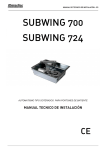
USER’S MANUAL ____________________________________________________________________________________ __________________ SUBWING 700 SUBWING 724 UNDERGROUND OPERATORS FOR SWING GATES USER’S MANUAL CE _______________________________________________________________________________________________________________ _________________ USER’S MANUAL ____________________________________________________________________________________ __________________ GENERAL SAFETY If correctly installed and used, this automation device satisfies the required safety level standards.However, it is advisable to observe some practical rules in order to avoid accidental problems. Before using the automation device, carefully read the operation instructions and keep them for future reference. Keep children, people and things outside the automation working area, par ticularly during its operation. Keep radio control or other control devices out of children’s reach, in order to avoid any unintentional automation activation. Do not intentionally oppose the leaf movement. Do not modify the automation components. In case of malfunction, disconnect the power supply, activate the emergency release to have access to the automation and request the assistance of a qualified technician (installer). Before proceeding to any outside cleaning operation, disconnect the power supply. Keep the photocell optical components and light signal devices clean. Check that the safety devices (photocells) are not obscured by branches or shrubs. For any direct assistance to the automation system, request the help of a qualified technician (installer). Have qualified personnel check the automation system once a year. Manual release activation could cause the door to be subject to uncontrolled movements in the case where any mechanical faults are present or the door is not balanced. Inspect the installation frequently if it shows any unbalance or signs of mechanical damage to cables and supports”. Do not use the operator if it needs to be repaired. Keep the instructions together with the technical brochure for future reference. This product was exclusively designed and manufactured for the use specified in the present documentation. Any other use not specified in this documentation could damage the product and be dangerous. The Company declines all responsibility for any consequences resulting from improper use of the product, or use which is different from that expected and specified in the present documentation. Do not install the product in explosive atmosphere. The construction components of this product must comply with the following European Directives: 2004/108/CEE, 2006/95/EEC, 98/37/EEC and subsequent amendments. As for all non-EEC countries, the above-mentioned standards as well as the current national standards should be respected in order to achieve a good safety level. The Company declines all responsibility for any consequences resulting from failure to observe Good Technical Practice when constructing closing structures (door, gates etc.), as well as from any deformation which might occur during use. The installation must comply with the provisions set out by the following European Directives: 2004/108/CEE, 2006/95/EEC, 98/37/EEC and subsequent amendments. Disconnect the electrical power supply before carrying out any work on the installation. Also disconnect any buffer batteries, if fitted. Fit an omnipolar or magneto thermal switch on the mains power supply, having a contact opening distance equal to or greater than 3,5 mm. Check that a differential switch with a 0.03A threshold is fitted just before the power supply mains. Check that earthing is carried out correctly: connect all metal parts for closure (doors, gates etc.) and all system components provided with an earth terminal. Fit all the safety devices (photocells, electric edges etc.) which are needed to protect the area from any danger caused by squashing, conveying and shearing. Position at least one luminous signal indication device (blinker) where it can be easily seen, and fix a Warning sign to the structure. The Company declines all responsibility with respect to the automation safety and correct operation when other manufacturers’ components are used. Only use original parts for any maintenance or repair operation. Do not modify the automation components, unless explicitly authorized by the company. Instruct the product user about the control systems provided and the manual opening operation in case of emergency. Do not allow persons or children to remain in the automation operation area. Keep radio control or other control devices out of children’s reach, in order to avoid unintentional automation activation. The user must avoid any attempt to carry out work or repair on the automation system, and always request the assistance of qualified personnel. Check that the stated temperature range is compatible with the place where the operator is to be installed. If present, the hold button (hold-to-run control) must be fitted within sight of the door but away from the moving parts, at a height of 1.5 m, and must not be accessible to the public. If the operator is fitted at a height lower than 2.5 m, you must guarantee an adequate degree of protection for the electrical and mechanical parts. Make sure that squashing is avoided between the moving parts and surrounding fixed parts. Fit all the safety devices (photocells, safety edges etc.) required to protect the area from any danger of squashing, drawing in and shearing. After completing the installation, ensure that the motor is set correctly and that the protection and release systems operate correctly. Anything which is not expressly provided for in the present instructions is not allowed. _______________________________________________________________________________________________________________ _________________ USER’S MANUAL ____________________________________________________________________________________ __________________ 1. GENERAL OUTLINES Electromechanical operator designed to automate residential-type gates. The operator keeps the gate blocked on closing and on opening, without needing an electric lock. The operator has no mechanical clutch. It must be controlled by an electronic control panel provided with torque setting. The end-of-stroke operation is managed by the control panel. SUBWING is a series of powerful and silent gearboxes made for the automatic movement of the winged gates and doors up to 3 meters for the leaf. SUBWING 700 and 724 version, prepared for intensive use, are an ideal choice for condo applications. 2. INSTALLATION Preliminary checks Check that: • The gate structure is sufficiently sturdy. • Also make sure that the actuator pushes against the leaf reinforced section. • The leaves move manually and without effort all along their stroke. • The door stop plates are fitted at the end of both closing and opening strokes. • If the gate has not been recently installed, check the wear condition of all components. • Repair or replace faulty or worn parts. Size of gate The size of the gate is a very important factor. Wind can slow the gate down or distort it, causing a marked increase in the force required to move it. Weight of gate The specified weight of the gate only gives a rough indication of the output required from the drive. The function which the gate is expected to perform is also important in this connection. Temperature Low outdoor temperatures can make it more difficult or impossible to set the gate into motion (because of soil changes). High outdoor temperatures may cause the temperature cut-off (at about 135°C) to be triggered earlier. Duty factor The drives have a maximum duty factor of around 30-50% (50% of one hour). This factor depends heavily on many influencing factors. The drive is not suitable for systems with a high cycling rate (continues operations) and such use would mean that the guarantee be comes invalid. _______________________________________________________________________________________________________________ _________________ USER’S MANUAL ____________________________________________________________________________________ __________________ NOTE - For intensive use ask other OIL or 24 V type of underground operator. Gate dimension and weight Tab 1 Weight max leaf 700 724 300Kg 250Kg Power supply cable The board power supply cable must be of the H 05 RN-F type or equivalent. The equivalent cable must guarantee: - permanent outside use - rated voltage of 300/500 V - maximum temperature on the cable surface of +50° C - minimum temperature of -25° C Moreover, it must have a minimum section of 3 x 1.5 mm2 and, for the cable to hold correctly, it must be provided with an external sheath of Ø = 7.1 to 9.6 mm. The wiring of the terminal board must be carried out as shown in Fig. 3 M1= operation 1 M2= operation 2 T= earthing N = common WARNING! When the power supply cable is damaged, it must be replaced by the manufacturer or its technical assistance service, or else by a person having similar qualification, in order to prevent any risk. 3. MOUNTING BOX Check the overall dimensions (fig. 1) to ensure that you will have enough space to dig out a hole for the motor housing. The opening angle of the gate has an important influence on the position of the motor housing. - The motor housing must be set in concrete. The piping for the electrical wiring and the drainage should be borne in mind in this connection (fig 1). - Remember that the final dimensions of the installation (including plaster layer etc) determine the room available. - The top of the motor housing should be slightly higher than the concrete surrounding it. Fig.1 Fig.2 _______________________________________________________________________________________________________________ _________________ USER’S MANUAL ____________________________________________________________________________________ __________________ 4. DRAINAGE: If the drainage of the installation cannot be connected up to the main drains, it may be possible to make use of a drainage pit. The floor must be permeable to water, and the cover of the motor housing should be protected against heavy rainfall or surface water with silicone sealant. The drainage pit should be dug out so as to be appreciably lower than the bottom of the motor housing, and its capacity should exceed that of the motor housing. The pit should be filled with coarse rubble or gravel, and should be tiled to keep out sediment and water from the top and sides. Facilities should be provided to lead any water getting into the motor housing to this drainage. Fig.3 5. OPENING ASSEMBLY FROM 90° TO 110° The pivot point of the gate can be found on the mounting box. - Operator (code SUBWING 700) opens gates up to 110° - Mount the arm which will be later welded to the gate and insert the bearing ball (fig 4, fig. 5). Fig.4 - For openings up to 180° use the special arm with chain (our code RL 180). - Once the motor housing has been set in place, the gate can be mounted on top of it. Additional hinges will certainly be needed to ensure proper guidance fig. 5 The arm with the facilities for switching to manual operation must be welded on to the gate. Turning the special key in the hole provided for it switches the system to manual operation so that the gate can be opened by hand if necessary. 6. GROUND GATE STOPS Mechanical stops must be mounted on the ground to limit the movement of the gate ( Fig. 6). _______________________________________________________________________________________________________________ _________________ USER’S MANUAL ____________________________________________________________________________________ __________________ . Fig.6 7. THE ELECTRICAL PLANT SET-UP Lay out the electrical installation fig. 7 with reference in force for electrical installation. The mains power supply connections must be kept totally separate from the service connections (photocells, electric edges, control devices etc.). Connect the control and safety devices in compliance with the previously mentioned electrical installation standards. The main automation components are (fig.5): Fig.7 Control panel and incorporated receiver Key selector Blinker tuned in with antenna Operator Pair of outside photocells Pair of inside photocells 1-2-4 channel transmitter Antenna cable Warning! For actuator wiring and accessory connection, refer to the relevant instruction manuals. The control panels and accessories must be suitable for use and conform to current standards. Should the opening or closing direction be incorrect, it is possible to invert the connections of operation 1 and operation 2 on the control board. The first command after an interruption of the power supply should be an opening maneuver. 8. ASSEMBLY OF THE MOTOR Plug the motor arm onto the motor and fix it with bolt and nut. - Mount both mechanical limit switches (fig. 8) _______________________________________________________________________________________________________________ _________________ USER’S MANUAL ____________________________________________________________________________________ __________________ - Place motor in box. The motor shaft should point outwards. In the entrance. Install motor power cable and lead it upwards and out of the box to the distribution box. Do not distribute power in this box. - Tighten motor with the four bolts (fig. 8). Position connecting arm, secure bolts and washers. In the connecting arm plain bronze bearings with very tight fits. Fig.8 Mount the gate CLOSED adjustable mechanical limit stop. Don’t completely tighten the bolts yet so that the gate can still move (Fig. 9) Mount the gate OPEN adjustable mechanical limit stop. Don’t tighten the bolts completely yet but allows some movement 9. SETTING OF THE MECHANICAL ADJUSTABLE END STOPS Mechanical stops cannot be set until the motor has been connected to the power supply. If the settings are made without the controller the motor can be directly connected to 230V. For this purpose the capacitor must also be connected. See electrical connections. Fig.9 - Close the gate as far as required position or to the floor stop. Turn the end stop so that the bolt and the fitting meet the connecting arm accurately. Set with the nut and then tighten all parts (fig. 10). - Open the gate as far as required position or to the floor stop. Turn the end stop so that the connecting arm is accurately met at right angles (90°).Set with the nut and then tighten all parts (fig.10) Fig.10 Assembly with RL-180° Fix on the chain wheel. Fix it with the bolts and nuts. - Place motor in the box. Install motor power cable and lead it upwards out of the box. - Tighten motor with the four bolts. - Place chain on gears and secure with chain joint. Fig.11 ATTENTION The 180° gearing has no stopping devices in the box. It is extremely important to built strong mechanical stops on the ground. _______________________________________________________________________________________________________________ _________________ USER’S MANUAL ____________________________________________________________________________________ __________________ 10. ADJUSTING THE PUSHING FORCE WARNING: Check that the impact force value measured at the points established by the EN 12445 standard is lower than that specified in the EN 12453 standard The pushing force is calibrated by means of the torque regulator in the control unit. The optimum torque must allow a complete opening or closing cycle with the minimum force necessary. An excessive torque can reduce the anti-crush safety. In the other case, an insufficient torque can impede the maneuvers. Consult the control unit’s instruction manual. 11. CHECKING THE AUTOMATION Before considering the automation completely operational, the following checks must be made with great care: • Check that all the components are firmly anchored. • Control all the safeties work properly (i.e. photocells, pneumatic skirt, etc.). • Check the emergency maneuvers control. • Check the opening and closing maneuvers using the controls. • Check the control unit’s electronic logic in normal (or customized) operation. 12. USE OF THE AUTOMATION Since the automation may be remote controlled either by radio or a Start button, it is essential that all safeties are checked frequently. Any malfunction should be corrected immediately by a qualified specialist. Keep children at a safe distance from the field of action of the automation. 13. THE CONTROLS With the automation the gate has a power driven opening and closing. The controls can come in various forms (i.e. manual, remote controlled, limited access by magnetic badge, etc.) depending on needs and installation cha racteristics. For details on the various command systems, consult the specific instruction booklets. Anyone using the automation must be instructed in its operation and controls. 14. MAINTENANCE When carrying out maintenance operation on the controller, disconnect it from the mains power supply. The actuator does not require periodical maintenance operations. • Check the safety devices of the gate and automation. • Periodically check the pushing force and correct the value of the electric torque in the control board if necessary. • In case of unsolved operation failures, disconnect the unit from the mains power supply and ask for the intervention of qualified personnel (installer). When the unit is out of order, activate the manual release to perform manual opening and closing maneuvers. 15. NOISE The aerial noise produced by the gear motor under normal operating conditions is constant and does not exceed 70dB (A). 16. TROUBLES AND SOLUTIONS _______________________________________________________________________________________________________________ _________________ USER’S MANUAL ____________________________________________________________________________________ __________________ Incorrect operation of gear-motor Check for the presence of power supply to the gear motor using a suitable instrument after opening or closing commands have been given. If the motor vibrates but does not turn, the causes could be the following: a) incorrect connection of the C common wire. b) operation capacitor not connected to the terminals on the control board. c) if the moving direction of the leaf is opposite to the right one, invert the motor running connections. Incorrect operation of the electrical accessories All control and safety devices can cause, in case of failure, malfunctioning or stoppage of the automation. To identify the failure, it is advised to disconnect all the devices of the automation one by one until the one causing the problem is found. After fixing or replacing the defective device, reset all the devices previously disconnected. Refer to the relevant instruction manual for all the devices installed on the automation. 17. MANUAL OPENING . Emergency release is obtained by using the key provided, on the release unit which is located under the gate, on the protruding section of the lever-pivot. To release, insert the key and turn it by about 90° (fig.12). If the leaf is equipped with an electric lock, release the electric lock as well. To open/close the gate, push it manually. To restore motor-driven operation, reposition the gate by aligning it with the lever bearing the lock unit, and turn the key (fig.12) checking that engagement is correctly restored. Fig.12 18. OPERATOR CHARATERISTIC SUBWING 700 SUBWING 724 Supply (Vac 50Hz) 230 230 Engine supply (Vac/Vdc) 220 24 Engine power (W) 350 50 Max thrust (N/m) 350 300 Max swing weight (kg) 300 250 Thermal protection integrated Temperature range (°C) -25 / +70 -25 / +70 Cycle (%) 30 90 Weight (Kg) 10 10 _______________________________________________________________________________________________________________ _________________ USER’S MANUAL ____________________________________________________________________________________ __________________ _______________________________________________________________________________________________________________ _________________