1
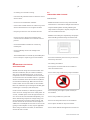
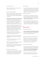
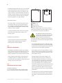
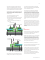
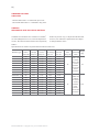
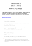
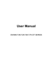
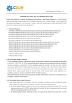
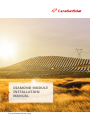
DIAMOND MODULE
INSTALLATION
MANUAL
For professional use only
EN-Rev IM-FDM-EN/1.1 Copyright © Aug. 2015. Canadian Solar Inc.
1.0
|4
GENERAL INFORMATION
1.1 INSTALLATION MANUAL DISCLAIMER
|4
1.2 LIMITATION OF LIABILITY
|4
2.0 SAFETY PRECAUTIONS
|4
3.0 |5
MECHANICAL / ELECTRICAL SPECIFICATIONS
4.0 UNPACKING AND STORAGE
|5
5.0 MODULE INSTALLATION
|6
5.1 MODULE WIRING
|7
5.2 MODULE GROUNDING
|8
6.0 MOUNTING INSTRUCTIONS
|8
7.0
|9
MAINTENANCE
AMENDED EDITIONS AND DATES
|10
ANNEX A: MECHANICAL AND ELECTRICAL RATINGS
|10
ANNEX B: DOUBLE GLASS MODULE
INSTALLATION MANUEL SUPPLEMENT
|11
www.canadiansolar.com
4 |
1.0
GENERAL INFORMATION
PV module interconnectors pass direct current
(DC) when exposed to sunlight or other light
sources. Contact with electrically active parts
This general manual provides important safety
of the module, such as terminals, can result in
information relating to the installation, maintenance
injury or death, irrespective of whether or not the
and handling of double glass solar modules. Profes-
module and the other electrical equipment have
sional installer must read these guidelines carefully
been connected.
and strictly follow these instructions. Failure to
follow these instructions may result in death, injury
Avertissement: Toutes les instructions devront
or property damage. The installation and hand-
être lues et comprises avant de procéder à
ling of PV modules requires professional skills and
l’installation, le câblage, l’exploitation et/ou
should only be performed by qualified professionals.
l’entretien des panneaux. Les interconnexions
Installers must inform end -users (consumers) the
des panneaux conduisent du courant continu
aforesaid information accordingly.
(CC) lorsque le panneau est exposé à la lumière
The word "module" or "PV module" used in this
du soleil ou à d’autres sources lumineuses.
manual refers to one or more double glass solar mo-
Tout contact avec des éléments sous tension
dules. This manual is only valid for the double glass
du panneau tels que ses bornes de sortie peut
module type CS6K-P-FG and CS6X-P-FG. Please retain
entraîner des blessures ou la mort,
this manual for future reference. We recommend
que le panneau soit connecté ou non.
visiting www.canadiansolar.com regularly for the
most updated version.
GENERAL SAFETY
1.1
INSTALLATION MANUAL DISCLAIMER
· All modules must be installed by licensed electricians
in accordance with the applicable electrical codes
such as, the latest National Electrical Code (USA) or
The information contained in this manual is subject
Canadian Electric Code (Canada), or other national
to change by Canadian Solar Inc. without prior
or international electrical codes.
notice. Canadian Solar Inc. gives no warranty of any
kind whatsoever, either explicitly or implicitly,
Protective clothing (non-slip gloves,
with respect to the information contained herein.
clothes, etc.) must be worn during
installation to prevent direct contact
with 30 VDC or greater, and to protect
1.2
LIMITATION OF LIABILITY
your hands from sharp edges.
Prior to installation, remove all metallic
Canadian Solar Inc. shall not be held responsible for
jewelry to prevent accidental exposure
damages of any kind, including – without limitation –
to live circuits.
bodily harm, injury or damage to property, in
connection with handling PV modules, system
When installing or handling modules in
installation, or compliance or non-compliance with
light rain, morning dew or strong wind,
the instructions set forth in this manual.
appropriate safety measures should be
taken to avoid damaging the modules or
injuring people.
2.0
SAFETY PRECAUTIONS
Do not allow children and unauthorized
persons near the installation site or
Warning: Before attempting to install,
storage area of modules.
wire, operate and/or service the module
and other electrical equipment, all instructions should be read and understood.
· If the disconnects and over current protective
devices (OCPD) cannot be opened or the inverter
cannot be powered down, cover the fronts of
modules in the PV array with an opaque material
to stop the production of electricity when installing
EN-Rev IM-FDM-EN/1.1 Copyright © Aug. 2015. Canadian Solar Inc.
| 5
or working on a module or wiring.
4.0
UNPACKING AND STORAGE
· Use electrically insulated tools to reduce the risk of
electric shock.
· Do not use or install broken modules.
PRECAUTIONS
· Module should be stored in a dry and ventilated
environment to avoid direct sunlight and moisture.
· Contact with module surfaces or frames may cause
electric shock if the front or rear glass is broken.
· Unpack module pallets carefully, following the
steps shown on the pallet. Unpack, transport and
· Keep the junction box cover closed at all times.
store the modules with care.
· Modules must always be unpacked by two people.
· Do not connect or disconnect modules when
When handling modules always use both hands.
current from the modules or an external source is
present.
· Do not disassemble a module or remove any
module part.
· Do not artificially concentrate sunlight onto
a module.
· The PV module does not contain any serviceable parts.
Do not attempt to repair any part of the module.
· Do not lift modules by their wires or junction box;
lift them by the frame.
3.0
MECHANICAL / ELECTRICAL
SPECIFICATIONS
· No stacking of modules.
· Do not place excessive loads on the module or
twist the module frame.
Module electrical ratings are measured under Standard Test Conditions (STC) of 1 kW/m2 irradiance,
· Do not stand, step, walk and/or jump on modules.
with an air mass (AM) spectrum of 1.5, and a cell
temperature of 25°C. Detailed electrical and mechanical characteristics of Canadian Solar Inc. crystalline
silicon PV modules can be found in Annex A (Mechanical And Electrical Ratings). Main electrical characteristics under STC are also stated on each module
label. The maximum system voltage for double glass
module type is 1000V (UL) and 1500V (IEC).
Under certain conditions, a module may produce
more current or voltage than its STC rated power. As
· Do not drop or place objects (such as tools) on
the modules.
a result, a module open-circuit voltage and short-circuit current under STC should be multiplied by 1.25
· Do not carry modules on your head.
when determining component voltage ratings, conductor ampacities, overcurrent device ratings, and
· Do not use sharp instruments on the modules.
the size of controls connected to the PV output. An
additional 1.25 multiplier for the short-circuit current
· Do not place modules on top of each other
(giving a total multiplier of 1.56), may be applicable
when sizing conductors and fuses, as described in
· Do not leave modules unsupported or unsecured.
section 690-8 of U.S. NEC.
www.canadiansolar.com
6 |
· Do not change the wiring of bypass diodes.
· Keep all electrical contacts clean and dry.
cal mounting instructions.
· Canadian Solar Inc. CS6K-P-FG and CS6X-P-FG
modules have been certified by CSA as Type 3 for
fire performance.
PRODUCT IDENTIFICATION
· When installing the modules on rooftop, please
· Each module is equipped with two identical barcodes (one inside the laminate under the front
ensure the assembly is mounted over a fire resistant
roof covering rated for the application.
glass, the second on the rear side of the module)
that act as a unique identifier. Each module has a
unique serial number containing 14 digits.
· A nameplate is also affixed to the rear glass of
· A photovoltaic system composed of UL1703
certified modules mounted on a UL2703 certified
mounting system should be evaluated in combina-
each module. This nameplate specifies the model
tion with roof coverings in accordance with UL1703
type, as well as the main electrical and safety cha-
standard, with respect to meeting the same fire
racteristics of the module.
classification as the roof assembly.
5.0
MODULE INSTALLATION
· Mounting systems with a System Fire Class Rating
(Class A, B or C), tested in conjunction with fire
rated “Type 3” rated modules, are considered acceptable for use with Canadian Solar Inc. modules,
provides the mounting system does not violate any
PRECAUTIONARY MEASURES
other requirements of this manual.
AND GENERAL SAFETY
· Any mounting system limitations on inclination or
· Prior to installing modules please obtain infor-
accessories required to maintain a specific System
mation about any requirements and necessary
Fire Class Rating should be clearly specified in the
approvals for the site, installation and inspection
installation instructions and UL2703 certification of
from the relevant authorities.
the mounting system supplier.
· Check applicable building codes to ensure that
the construction or structure (roof, facade,
ENVIRONMENTAL CONDITIONS
support, etc.) can bear the module system load.
· The module is intended for use in general open-air
· CS6K-P-FG and CS6X-P-FG solar modules have
climates, as defined in IEC 60721-2-1: Classification
been qualified for Application Class A (equivalent
of environmental conditions Part 2-1: Environmental
to Safety Class II requirements). Modules rated
conditions appearing in nature - temperature and
under this class should be used in systems opera-
humidity.
ting at voltage above 50 V or power above 240 W,
where general contact access is anticipated.
· Please consult the Canadian Solar Inc. technical
support department for more information on the
Please note DO NOT STAND OR STEP on the
modules under any circumstances.
use of modules in special climates.
Localized heavy loads may cause severe micro-
Do not install modules near naked flames
cracks at cell level, which in turn may compromise
or flammable materials.
module reliability. Failure to comply with the above
caution will void Canadian Solar Inc.’s warranty.
Do not immerse modules in water or
constantly expose modules to water
(either fresh or salt) (i.e. from fountains,
SYSTEM FIRE RATING
· The fire rating for this module is only valid when
the product is installed as specified in the mechani-
EN-Rev IM-FDM-EN/1.1 Copyright © Aug. 2015. Canadian Solar Inc.
sea spray).
· Exposing modules to salt (i.e. marine environments)
or sulfur (i.e. sulfur sources, volcanoes) incurs the
| 7
risk of module corrosion.
· Failure to comply with these instructions will void
Canadian Solar Inc. warranty.
AVOID SHADING
· Even minor partial shading (e.g. from dirt deposits)
reduces yields. A module can be considered to be
unshaded if its entire surface is free from shading
all year round. Sunlight should be able to reach the
INSTALLATION REQUIREMENTS
· Ensure that the module meets the general technical
module even on the shortest day of the year.
RELIABLE VENTILATION
system requirements. Ensure that other systems
components do not damage modules mechanically
or electrically.
· Sufficient clearance (at least 3.94 in (10 cm)) between the module frame and the mounting surface
is required to allow cooling air to circulate around
· Modules can be wired in series to increase voltage
or in parallel to increase current. To connect modules
the back of the module. This also enables condensation or moisture to dissipate.
in series, connect the cables from the positive
terminal of one module to the negative terminal
· Any other specific clearance required for main-
of the next module. To connect in parallel, connect
taining a system fire rating should prevail. Detailed
the cables from the positive terminal of one
clearance requirements pertaining to system fire
module to the positive terminal on the next module.
ratings must be provided by your racking supplier.
· Only connect the quantity of modules that corresponds to the voltage specifications of the inverters
used in the system. Modules must not be connec-
5.1
MODULE WIRING
ted together to create a voltage higher than the
maximum permitted system voltage, even under
CORRECT WIRING SCHEME
the worst local temperature conditions.
· Ensure that the wiring is correct before starting up the
· Only modules with similar electrical outputs
system. If the measured open circuit voltage (Voc) and
should be connected in the same series to avoid
short-circuit current (Isc) differ from the specifications,
or minimize mismatch effects in arrays.
this indicates that there is a wiring fault.
· To minimize risk in the event of an indirect lightning strike, avoid forming loops when designing
CORRECT CONNECTION OF PLUG CONNECTORS
the system.
· Make sure that connections are safe and tight.
· The recommended maximum series fuse rating
is stated in a table in the Annex.
Plug connector should not be subjected to stress
from the exterior. Connectors should only be
used to connect the circuit. They should never
· Modules should be safely fixed to bear all expected
be used to turn the circuit on and off.
loads, including wind and snow loads.
·A minimum clearance of 0.255 in (6.5 mm) or more
USE OF SUITABLE MATERIALS
between modules is required to allow for thermal
expansion of the modules.
· Only use dedicated solar cable and suitable plugs
(wiring should be sheathed in a sunlight-resistant
conduit or, if exposed, should itself be sunlight-
OPTIMUM ORIENTATION AND TILT
resistant) that meet local fire, building and electrical
regulations. Please ensure that all wiring is in
· To maximize your annual yield, find out the optimum
perfect electrical and mechanical condition.
orientation and tilt for PV modules in your region.
The highest yields are achieved when sunlight
shines perpendicularly onto the PV modules.
· Installers may only use 4 mm2 (12 AWG) single
conductor cable listed and labeled as PV Wire or
www.canadiansolar.com
8 |
TUV 2PfG1169 approved, that is 90°C wet rated with
proper insulation that is able to withstand the maximum possible system open-circuit voltage. Only
(-)
copper conductor material should be used. Select a
(+)
suitable conductor gauge to minimize voltage drop
and ensure that the conductor ampacity complies
with local regulations (i.e. NEC 690.8(D)).
CABLE PROTECTION
· Secure the cables to the mounting system using
UV-resistant cable ties. Protect exposed cables
from damage by taking appropriate precautions
(e.g. placing them inside a plastic conduit). Avoid
exposure to direct sunlight.
Glass
Junction box
Plastic corners
Cables and connectors
(*) Cable standard length is 39.4 in (1000 mm)(-/+).
Cable optional lengths are13.8 in (350mm) (-) and
· A minimum bending radius of 60 mm is required
19.7 in (500mm) (+) for portrait installation.
when securing the junction box cables to the
The applicable regulations pertaining
racking system.
to work safety, accident prevention and
securing the construction site must be
CONNECTOR PROTECTION
observed. Workers and third party
personnel shall wear or install fall arrest equipment.
· Protect exposed connectors from weathering
damage by taking appropriate precautions.
Any third party need to be protected against injuries
and damages.
Avoid exposure to direct sunlight.
· The mounting design must be certified by a regis-
5.2
MODULE GROUNDING
· EQUIPMENT GROUNDING: double glass modules
tered professional engineer. The mounting design
and procedures must comply with local codes and
requirements from all relevant authorities.
· Each module must be securely fastened at a mini-
do not present any exposed conductive parts, and
mum of 4 points on two opposite sides. Canadian
therefore do not require to be electrically groun-
Solar Inc. recommends mounting rails with a mini-
ded for compliance to the National Electrical Code.
mum width of 60 mm.
· Proper equipment grounding is still required for
· Install and tighten the module clamps to the
the racking system in compliance with all local
mounting rails using the torque stated by the
electrical codes and regulations. Please refer to the
mounting hardware manufacturer. System desig-
racking system user instructions.
ner and installer are responsible for load calculations and for proper design of support structure.
It is recommended to use a torque wrench for
6.0
MOUNTING INSTRUCTIONS
installation. Tightening torques should respectively
be within 20~26 Nm (14.8~19.2 ft-lb) (23 Nm (17.0
ft-lb) is recommend) for M8x1.25 coarse thread
STANDARD MODULES
bolts, depending on bolt class (recommended bolt
For a clear understanding of our modules, please
grade is 8.8).
refer to the illustration of a module shown below:
·Use appropriate corrosion-proof fastening materials. All mounting hardware (bolts, spring washers,
flat washers, nuts) should be made with stainless
steel.
EN-Rev IM-FDM-EN/1.1 Copyright © Aug. 2015. Canadian Solar Inc.
| 9
· Clamp material should be anodized aluminum
must only be positioned within the authorized
alloy or steel of appropriate grade. One buffer
position ranges indicated in ANNEX B, depending
rubber material (Recommended material is EPDM)
on the configuration and load.
must be added between the clamp and the glass.
·The module is only considered to comply with
· Canadian Solar Inc. warranty may be void in cases
UL1703 when mounted as specified in the inst-
where improper clamps or unsuitable installation
ructions in ANNEX B. Any module without a frame
methods are found. When installing clamps, take
(laminate) shall not be considered to comply with
measures so as:
the requirements of UL 1703 unless the module is
mounted with hardware that has been tested and
1. Not to bend the laminate excessively.
evaluated with the module under this standard or
2. Not to cast shadow on the cells.
by a field Inspection certifying that the installed
3. Not to damage or scratch the surface of the glass.
module complies with the requirements of UL
4. To ensure the clamps overlap the module by
1703.
13 mm to 15 mm.
5. To ensure the thickness of the clamps is at
least 3 mm.
·Double glass modules can be mounted to a support structure by means of clamps. For recommen-
Spring washer
Nut
ded installation methods and load, please refer to
ANNEX B and contact your local representative for
Flat washer
Top Middle Clamp
further information. Failure to use a recognized
installation method will void Canadian Solar Inc.
Rubber
warranty.
7.0
MAINTENANCE
· Regular maintenance is required to keep modules
clear of snow, bird droppings, seeds, pollen, leaves, branches, dirt spots, and dust.
Glass
Rail
Spring washer
Bolt
Bottom Middle Clamp
do not require cleaning (rain will have a self-cleaning effect). If the module has become soiled,
Nut
Flat washer
· Modules with sufficient tilt (at least 15°), generally
it shall be washed with water and a non-abrasive
Top End Clamp
Rubber
cleaning implement (sponge) during the cool part
of the day. Do not scrape or rub dry dirt away, as
this may cause micro scratches.
· Snow should be removed using a soft brush.
· The system shall be periodically inspected to verify
the integrity of all wiring and supports.
· To protect against electric shock or injury, electrical or mechanical inspections and maintenance
should be performed by qualified personnel only
and on a regular basis.
Rail
Bolt
Bottom End Clamp Glass
· Please refer to our Installation Manual Annex
(Section Annex D: Module Cleaning Guideline) for
· Clamp positions are of crucial importance for the
more information on module cleaning.
reliability of the installation, The clamp centerline
www.canadiansolar.com
10 |
AMENDED EDITIONS
AND DATES
· The first edition Rev 1.0 is released in June. 2015
· The second edition Rev 1.1 is released in Aug. 2015.
ANNEX A:
MECHANICAL AND ELECTRICAL RATINGS
Standard Test Conditions are: irradiance of 1 kW/m2,
within ±10 percent or [0; +5 W] of the indicated valu-
air mass (AM) spectrum of 1.5, and cell temperature
es for Isc, Voc and Pmax. Specifications are subject
of 25°C. The electrical characteristics are respectively
to change without notice.
Table 1:
Specifications for CS6K-P-PG photovoltaic modules under STC
Module Type
Maximum Operating Operating Open Cir- Short Circuit Max. Series Overall
Weight
Power
voltage
current cuit Voltage Current
Fuse
Dimension
<kg>
Pmax <W> Vmp <V> Imp <A>
Voc <V>
Isc <A>
Rating <A> <mm>
CS6K-245P-FG
245
30.0
8.17
37.1
8.74
CS6K-250P-FG
250
30.1
8.30
37.2
8.87
CS6K-255P-FG
255
30.2
8.43
37.4
9.00
CS6K-260P-FG
260
30.4
8.56
37.5
9.12
CS6K-265P-FG
265
30.6
8.66
37.7
9.23
CS6K-270P-FG
270
30.8
8.75
37.9
9.32
CS6K-275P-FG
275
31.0
8.88
38.0
9.45
CS6K-280P-FG
280
31.3
8.95
38.2
9.52
CS6X-290P- FG
290
35.9
8.08
44.4
8.64
CS6X-295P- FG
295
36.0
8.19
44.5
8.76
CS6X-300P- FG
300
36.1
8.30
44.6
8.87
CS6X-305P- FG
305
36.3
8.41
44.8
8.97
CS6X-310P- FG
310
36.4
8.52
44.9
9.08
CS6X-315P- FG
315
36.6
8.61
45.1
9.18
CS6X-320P- FG
320
36.8
8.69
45.3
9.26
CS6X-325P- FG
325
37.0
8.78
45.5
9.34
CS6X-330P- FG
330
37.2
8.88
45.6
9.45
EN-Rev IM-FDM-EN/1.1 Copyright © Aug. 2015. Canadian Solar Inc.
15
1650 ˣ 992
ˣ 5.8 mm
(65.0 ˣ 39.1
ˣ 0.23 in)
without
j-box and
corner
protector
23
15
1968ˣ 992
ˣ 5.8mm
(77.5ˣ 39.1
ˣ 0.23 in)
without
junction-box
and corner
protector
27.5
| 11
ANNEX B:
DIAMOND MODULE INSTALLATION
MANUAL SUPPLEMENT
All the basic requirements of the main installation
have been approved as compatible with Canadian
manual should apply to this supplement, unless
Solar double glass module CS6K-P-FG.
otherwise specified. The following clamps in table 2
Table 2:
CS6K-P-FG compatible clamps
Mounting
Method
Clamp Type
Supplier
2-A
SA-TOK-UA (End
clamp) / SA-KOKUA (Middle clamp)
NISSEI METALS
CO.,LTD.
2-B
K2 frameless
clamp,4-7.2mm,
100mm
2-C
Clamp Image
K2 frameless
clamp,4-7.2mm,
200mm
Length Clamp Location
(mm)
Quantity
Load(Pa)
Certification Body
120
A=380 mm, four Downforce load≤2400 Pa
clamps
Uplift load ≤2400 Pa
VDE/CSA
100
A=380 mm, four Downforce load≤2400 Pa
clamps
Uplift load ≤2400 Pa
VDE/CSA
200
A=380 mm, four Downforce load≤5400 Pa
clamps
Uplift load ≤2400 Pa
VDE/CSA
K2 Systems GmbH
/ Everest Solar
Systems, LLC
2-D
Profi clamp, wiSchletter Inc. /
de,3-8mm, 100mm Schletter GmbH
100
A=380 mm, four Downforce load≤2400 Pa
clamps
Uplift load ≤2400 Pa
VDE/CSA
2-E
Profi clamp, wiSchletter Inc. /
de,3-8mm, 200mm Schletter GmbH
200
A=380 mm, four Downforce load≤5400 Pa
clamps
Uplift load ≤2400 Pa
VDE/CSA
2-F
GS-IC-L100 (Middle
clamp) / GSEC-L100
(End clamp)
100
A=380 mm, four Downforce load≤2400 Pa
clamps
Uplift load ≤2400 Pa
VDE/CSA
200
A=380mm, four Downforce load≤5400 Pa
clamps
Uplift load ≤2400 Pa
VDE/CSA
2-G
Xiamen Grace
SolarTechnology
co.,ltd.
GS-IC-L200 (Middle
clamp) / GSEC-L200
(End clamp)
www.canadiansolar.com
The following clamps in table 3 have been approved as compatible with Canadian Solar double glass module
CS6X-P-FG.
Table 3:
CS6X-P-FG compatible clamps
Mounting
Clamp Image
Method
Clamp Type
3-A
K2 frameless clamp,
4-7.2mm, 130mm
3-B
K2 frameless clamp,
4-7.2mm, 250mm
3-C
Profi clamp, wide,
3-8mm, 130mm
Supplier
K2 Systems
GmbH / Everest
Solar Systems,
LLC
Length Clamp Location
(mm)
Quantity
Certification
Body
Load (Pa)
130
A=440 mm, four Downforce load≤2400 Pa
clamps
Uplift load ≤2400 Pa
VDE/CSA
250
A=440 mm, four Downforce load≤5400 Pa
clamps
Uplift load ≤2400 Pa
VDE/CSA
130
A=440 mm, four Downforce load≤2400 Pa
clamps
Uplift load ≤2400 Pa
VDE/CSA
Schletter Inc./
Schletter GmbH
3-D
Profi clamp, wide,
3-8mm, 250mm
250
A=440 mm, four Downforce load≤5400 Pa
clamps
Uplift load ≤2400 Pa
VDE/CSA
3-E
GS-IC-L130 (Middle
clamp) / GS-EC-L130
(End clamp)
130
A=440 mm, four Downforce load≤2400 Pa
clamps
Uplift load ≤2400 Pa
VDE/CSA
250
A=440 mm, four Downforce load≤5400 Pa
clamps
Uplift load ≤2400 Pa
VDE/CSA
3-F
GS-IC-L250 (Middle
clamp) / GS-EC-L250
(End clamp)
Xiamen Grace
SolarTechnology
co.,ltd.
(*) Safety factor is not included in the maximum pressures provided in above table.
Compliance design rule with 1.5 safety factor should be recommended.
The mounting design and procedures must comply
with local electrical and building codes. System
designers and installers are solely responsible
CLAMPING LOCATION ILLUSTRATION
A
A
A
A
for load calculations and the proper design of the
supporting structure. For detailed information,
please follow local structural code or contact
professional structural engineer.
Clamping on module long side, four clamp points;
Mounting rails must run perpendicularly to the module long side;
CANADIAN SOLAR INC.
545 Speedvale Avenue West, Guelph, Ontario, Canada N1K 1E6
www.canadiansolar.com