1
Device Initialization
User Manual
version 1.8
2007 UNIS, spol. s r.o. ALL RIGHTS RESERVED
All brands or trademarks are property of their respective holders.
-1-
Device Initialization User Manual
CONTENTS
1. Introduction
3
1.1. Features And Benefits
1.2. Basic Terms And Definitions
1.3. Quick Start
1.4. Rapid Application Development Tools
3
3
4
5
2. User Interface
7
2.1. Main Menu
2.2. Device Initialization Window
2.3. Inspector Dialog
7
8
11
2.3.1. Inspector Items
13
2.4. Error Window
2.5. Options
14
15
3. Using The Tool
17
3.1. Peripheral Initialization Beans
3.2. Code Generation And Usage
3.3. Saving And Restoring The Design
3.4. Defining Interrupt Service Routines
3.5. Changing The CPU
3.6. Converting Code Warrior Project To Use The Device Initialization
3.7. Converting Device Initialization Project To Processor Expert
17
18
20
20
21
22
23
4. Tutorials
24
4.1. Tutorial Project 1 - Blinking LED In C
24
4.1.1. Tutorial project1, Step 1
4.1.2. Tutorial project1, Step 2
4.1.3. Tutorial project1, Step 3
4.1.4. Tutorial project1, Step 4
4.1.5. Tutorial project1, Step 5
25
26
27
28
28
4.2. Tutorial Project 2 - Blinking LED In Assembly
29
4.2.1. Tutorial project 2, Step 1
4.2.2. Tutorial project 2, Step 2
4.2.3. Tutorial project 2, Step 3
4.2.4. Tutorial project 2, Step 4
4.2.5. Tutorial project 2, Step 5
29
30
32
32
33
5. Help Revisions History
34
-2-
Device Initialization User Manual
Introduction
1. Introduction
Device Initialization is a fast, easy and user-friendly way to configure and generate a CPU peripheral
initialization code.
1.1. Features And Benefits
The Device Initialization features
• Graphical user interface with CPU package, peripherals and pins
• User-friendly access to initialization setup of CPU peripherals
• Initialization code generator
• User can select Assembly or C format for generated code
• Built-in detailed design specifications of Freescale CPUs
• Initialization options are automatically transformed into peripheral control registers values
• Easy way to view control register values resulting from the parameter settings. Changes are immediately
highlighted.
• Changes in peripheral control registers values are transformed backwards into bean parameters.
The key benefits of the Device Initialization tool
• Easy to learn design environment
• User friendly names of the peripheral features - no need to explore manuals for control register details.
• Easy changes in initialization
• Possibility to reuse the individual peripheral setup for other designs
• No need to generate code to see the resulting peripheral control registers values.
1.2. Basic Terms And Definitions
Bean - Peripheral Initialization bean - is a component that encapsulates initialization of a peripheral. A bean can
be configured using the Inspector. See chapter 3.1 Peripheral Initialization Beans for details.
CPU bean - the bean configuring the CPU core parameters. It cannot be removed from the project.
Design - all beans (the CPU bean and the Peripheral Initialization beans) with their customized parameters.
Inspector - window that allow to view and configure parameters of the selected bean.
Internal peripherals - internal peripherals of the CPU (ports, timers, A/D converters, etc. usually controlled by
the CPU core using special registers).
ISR - Interrupt Service Routine - code which is called when an interrupt occurs.
Module - source code module. Could be generated by the tool or created by the user and included in the project
(user module).
Peripheral settings - initialization parameters for an individual peripheral. These settings can be saved and
restored from the file.
Popup menu - this menu is displayed when the right mouse button is pressed on some graphical object.
-3-
Device Initialization User Manual
Introduction
Properties - parameters of the bean. Property settings define the internal peripheral initialization state that will
be converted to generated initialization code during the code generation process.
Target CPU - the CPU derivative used in a given design.
1.3. Quick Start
This chapter describes how to create a simple design, configure a device, generate initialization code and use it
in your application.
Step 1. Create an Empty Design
Use the Project Wizard to create a new project. It can be invoked by the click on the Create New Project button
in the Startup screen or using the menu command File | New Project....
Follow the step by step settings and in the Rapid Application Development Options page select the Device
Initialization option.
Step 2. Configure Peripherals
The Device Initialization window shows the CPU package with the available internal peripherals.
Click on a peripheral field to configure its initialization. A new peripheral initialization bean is automatically
created and the Inspector dialog window is displayed. It allows to view and change the parameters.
Use the Inspector to setup desired initialization parameters of the peripheral and confirm it by click on the OK
button and use the same steps for all peripherals that you wish to setup.
Step 3. Generate Code
Click the Generate Code button in the Device Initialization window.
Within the Options dialog, that appears immediately, select the desired initialization code format: C or
Assembly and using the field Generated module name specify the name of the output files you wish to generate
(you can also keep a default name 'MCUInit').
For more details on generated code see the chapter 3.2 Code Generation And Usage
Step 4. Use The Generated Code
The MCU_init initialization function call is automatically placed at the start of the main routine. Start writing
your application code after this initialization function call.
-4-
Device Initialization User Manual
Introduction
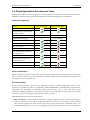
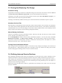
1.4. Rapid Application Development Tools
Metrowerks CodeWarrior offers two plug-ins for rapid application development: Processor Expert and Device
Initialization. Both tools have many advanced features that lead to development cycle acceleration.
Features Comparison
Feature
Processor Expert
Device Initialization
Peripheral Drivers
Initialization code only
C
C or Assembly
Easy to use graphical IDE
Interactive design specifications
of Freescale MCUs
Generated code
Generated code languages
Peripheral Init Beans
Low Level Beans
High Level Beans
Project Configurations
User-friendly linker parameter
file configuration
Generated code changes tracking
Timing settings in time units
(seconds, bauds etc.)
Free beans library on the web
User beans creation
Device Initialization
Device Initialization provides a fast and easy way to configure and generate an initialization source code for the
CPU. It contains only one set of beans: Peripheral Initialization Beans. The code initializing the peripheral can
be generated for use in Assembler or C.
Processor Expert
Processor Expert generates drivers in the C language that allows a hardware-independent access to CPU
peripherals. It contains large library of components called Embedded Beans. Embedded beans encapsulate the
initialization and functionality of embedded systems basic elements, such as CPU core, CPU on-chip
peripherals, standalone peripherals, virtual devices and pure software algorithms. These facilities are interfaced
to the user via properties, methods, and events (like in objects in OOP).
Embedded Beans levels of abstraction description:
• High Level Beans - The beans that are the basic set of beans designed carefully to provide functionality of
most microcontrollers on the market. An application built from these beans can be easily ported to another
microcontroller supported by the Processor Expert. This group of beans allows comfortable settings of a
desired functionality such as time in ms or frequency in Hz, the user doesn't have to know the details about
-5-
Device Initialization User Manual
Introduction
hardware registers.
• Low Level Beans - the beans dependent on the peripheral structure that allow the user to benefit from the
non-standard features of a peripheral. The level of portability is decreased due to a different bean interface
and the bean is usually implemented only for a CPU family offering the appropriate peripheral. However,
there is still implemented a comfortable settings of devices' features and effective set of methods and events.
• Peripheral Initialization Beans - the beans on the lowest level of abstraction. An interface of such beans is
based on the set of peripheral control registers. These beans cover all features of the peripherals and were
designed for initialization of these peripherals.
For more details please see the Processor Expert documentation.
-6-
Device Initialization User Manual
User Interface
2. User Interface
Menu
Device Initialization menu is integrated into the CodeWarrior IDE menu. See chapter 2.1 Main Menu for details.
Windows And Dialogs
The user interface of Device Initialization consists of the following windows (integrated in CodeWarrior IDE):
• Device Initialization - the main window graphically showing CPU package, structure and beans connected
to internal peripherals. It allows easily to add beans related to a specific peripheral to the design. See chapter
2.2 Device Initialization Window for details.
• Inspector - a window which allows user to setup peripheral initialization beans parameters. See chapter 2.3
Inspector Dialog for details.
• Error window - a window with errors, warning messages and hints from design checking and code
generation. See chapter 2.4 Error Window for details.
• Options - design and code generation related settings dialog. See chapter 2.5 Options for details.
2.1. Main Menu
Device Initialization menu is integrated in the CodeWarrior IDE main menu.
The menu contains the following commands:
• Initialize Device - creates a new design for the currently opened CodeWarrior project or opens an existing
one if it already exists on the disk. If the design is already opened, only the Device Initialization window is
activated. See chapter 2.2 Device Initialization Window for details.
• Backup Device Settings... - invokes a file selection dialog and if the user confirms the selection, it saves all
design settings using the selected file name. See chapter 3.3 Saving And Restoring The Design for details.
• Restore Device Settings... - invokes a file selection dialog and if the user confirms the selection, it loads all
design settings from the selected file name. See chapter 3.3 Saving And Restoring The Design for details.
• Update PE from Package... - allows to install a patch or update from the .PEUpd file.
• Options - invokes the Options dialog with the design-related settings with the values default for next code
generations. See chapter 2.5 Options for details.
• Generate Code {designname}.mcp - starts the initialization code generation process. See chapter 3.2 Code
Generation And Usage for details.
• View Report
Design Settings - generates a new document containing XML data with parameters and values of all
beans in the design.
Register Settings - generates a new document containing XML data with all registers (and their values)
that will be set within generated code.
Interrupt Usage - generates a new document containing XML data with all interrupts allocation by ISR
routines.
Pin Usage - generates a new document containing XML data of all pins allocated by the device
initialization design.
-7-
Device Initialization User Manual
User Interface
Help Menu
The menu with help pages links is integrated in the Help menu of the CodeWarrior under the Help | Device
Initialization submenu.
• Device Initialization help - displays the main help file.
• Device Initialization Tutorial - opens a tutorial showing the device initialization basics.
• List of all supported CPUs - displays the page with the list of CPUs supported in the current installation.
• List of all supported Peripheral Initialization Beans - displays the page with the list of CPUs supported in
the current installation.
• View Read Me and Revision History - shows the document containing details related to the current version
and the history of revisions and changes of the Device Initialization tool.
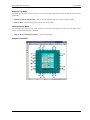
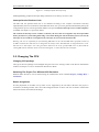
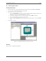
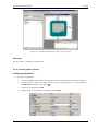
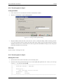
2.2. Device Initialization Window
The Device Initialization window is the main window of the Device Initialization design. The window contain
the design control buttons at the top of the window and working area that allows the user to browse and
configure the CPU peripherals. This window can be opened using the command Device Initialization | Initialize
Device.
Design Control Buttons
The window contains the following control buttons:
• Select CPU package - lists available packages from the current target CPU allows the user to choose one
that will be used in the design. See chapter 3.5 Changing The CPU for details.
• Generate Code - invokes the Code Generation dialog allowing the user to generate the initialization code
according to the current settings. See chapter 3.2 Code Generation And Usage for details.
• Backup... - invokes a file selection dialog and if the user confirms the selection, saves all design settings
using the selected file name. See chapter 3.3 Saving And Restoring The Design for details.
• Restore... - allows to restore the whole design from a file. File selection dialog is invoked immediately. See
chapter 3.3 Saving And Restoring The Design for details.
• Help - opens this help page.
Work Area
This area allows the user to configure the CPU peripherals by adding Peripheral Initialization Beans. See chapter
3.1 Peripheral Initialization Beans for details.
The following view modes are available:
• Package View of the CPU mode.
To configure a peripheral click on the peripheral field.
• Alphabetically ordered peripherals list mode.
To configure a peripheral click on its name or icon.
Control Icons
•
- rotates the CPU by 90 degrees.
-8-
Device Initialization User Manual
User Interface
•
- zoom-in - increases the package diagram size and detail level.
•
- zoom-out - decreases the package diagram size and detail level.
•
- activates the Package View mode.
•
- activates the Peripherals List mode.
Package View Mode
This is the default view mode for the design. In this mode, the window contains:
• Peripherals available on the CPU and their allocation by beans.
• Pins and their allocation by beans
• Useful information that are available in status line if the mouse cursor is placed on pin, bean or peripheral
The following information about each pin is displayed on the package:
• pin name (default or user-defined)
• icon of a bean that uses (allocates) the pin
• direction of the pin (input, output, or input/output) symbolized by blue arrows, if a bean is connected
Some pins cannot be used by the user because they are allocated by special signals such as power signals,
external or data buses. Special pins are indicated by special blue icons, for example
special signals could be influenced by the CPU bean properties.
. The allocation of pins by
Peripheral List
This mode shows the alphabetically ordered list of all CPU peripherals and their allocation. Unallocated
peripherals have a gray icon.
Hints
A hint will appear when the mouse cursor is placed on a specific item:
A pin hint contains:
(note: The pin hint is available in package view mode only)
• pin number
• pin name
• owner of the pin (bean that allocates it)
• short pin description
Bean icon hint contains:
• bean type
• bean description
-9-
Device Initialization User Manual
User Interface
Bean Pop-up Menu
This menu appears when the user clicks on a bean icon with the right mouse button. It contains the following
commands:
• Disable Peripheral Initialization - removes the selected bean with all its settings from the design.
• Help on Bean - opens the help pages related to the selected bean.
General Pop-up Menu
This menu appears when the user clicks anywhere in the Device Initialization window with the right mouse
button. It contains the following command:
• Help on Device Initialization Window - shows this help page.
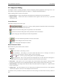
Sample Screenshot
- 10 -
Device Initialization User Manual
User Interface
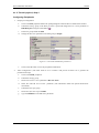
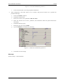
2.3. Inspector Dialog
The Inspector allows to modify parameters of beans configuring internal peripherals of the target CPU. ( For
more details on the peripheral beans please see chapter 3.1 Peripheral Initialization Beans.)
Inspector dialog window consists of two panels:
• Bean Parameters - contains the parameters that influence the initialization of the selected device.
• Register Details - contains the values of individual control registers that will be set by a generated
initialization code.
Control Buttons
The buttons description from left to right:
•
- removes the currently opened peripheral initialization bean from the design.
This command is not available for the CPU bean.
•
- opens the file selection dialog and saves parameters to the selected file.
•
- opens the file selection dialog and restores parameters from the selected file.
•
- opens a help page with the description of the bean parameters.
•
- saves the initialization parameters and closes the window
•
- cancels changes and closes the window
•
- opens this help page of the Inspector window.
Bean Parameters Panel
Bean Parameters panel contains the four columns:
• Item status
green checkmark - item setting is correct
red exclamation - item setting is not correct. Items that cause errors or warnings are written in
magenta color. See description in the last column or the Error Window.
plus or
minus - item is a group of settings that can be expanded/collapsed.
light background - item is version specific and is displayed only for CPU derivatives that support it.
These items cover the special capabilities of the CPU that are not present for all CPUs.
• Item names - items that are to be set are listed in the second column of the inspector. Groups of items
describing certain features may be collapsed/expanded by double clicking on the first line of the group.
• Selected settings - the settings of the items are made in the third column. See chapter 2.3.1 Inspector Items
for list of item types.
• Setting status - the current setting or an error status may be reflected on the same line, in the rightmost
column of the inspector. The error is also displayed in the item's hint.
A parameter can be presented as read only and the user cannot change its content. Such read only values are
gray.
- 11 -
Device Initialization User Manual
User Interface
Register Details
This panel shows values of individual control/data registers related to the currently selected CPU peripheral and
reflects the settings in the Bean Parameters panel.
The following two types of rows can be found in this panel:
• Whole register content
The row contains the following four columns:
Status field - This field contains
plus or
clicking the icon to show/hide individual bits.
minus - each register can be expanded/collapsed by
Name - name of the register according to the CPU datasheet.
Address - address of a register.
Init. Value - the initialization value of a register/bit computed according to the settings in Bean
Parameters panel. This is the last value written by the initialization function to the register.
Note: For some registers, the value read from the register afterwards can be different than the last
written value. For example, some interrupt flags are cleared by writing 1. Please see the CPU manual
for details on registers behavior.
If the row is active, the value can be changed using the keyboard. The field also contains a radix button
(H,D,B) that allows to switch between Hexadecimal, Decimal and Binary formats of the value.
The value that contains undefined bits is always shown in binary format.
Register Map - graphical representation of the initialization value. The colors represent the state of
individual bits:
(White) = value 0
(Black) = value 1
(Gray) = bit has no meaning for initialization of the peripheral (reserved, read-only or related to
another peripheral) or the value of the bit is undefined.
• Individual bit of the register
The row contains the bit value icon (0 or 1) and the name of the bit. Bits are sorted from the highest to lowest
weight. The bit rows of a register can be shown / hidden using the
register row.
/
icons in the status field of the
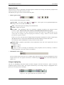
Changes Highlighting
The user can immediately watch the impact of his/her changes in the Bean Parameters panel on the CPU
peripheral registers and bits values. The registers influenced by a last settings change are highlighted with a
green color (see the picture for example).
Figure 2.4 - The register affected by the parameter change
- 12 -
Device Initialization User Manual
User Interface
The changes made to a register values are automatically analyzed and transformed into the bean parameters
values. Such parameters changes are highlighted the same way the register changes are.
The changes highlighting works only in the case that the bean had been set- up correctly before the change was
made and the new setup is correct as well and there is no error reported in a bean settings. If there is an error in a
bean settings, the after-reset values are shown.
2.3.1. Inspector Items
The following types of the items could be found in the Inspector:
• Boolean Group - A group of settings controlled by this boolean property. If the group is enabled, all the
items under the group are valid; if it is disabled, the list of items is not valid. Clicking the + sign will
show/hide the items in the group but doesn't influence value nor validity of the items.
• Boolean yes / no - The user can switch between two states of the property using a round icon
• Enumeration - Selection from a list of values. If the user clicks on the arrow icon (
values for the property is offered.
.
), a list of the possible
• Enumeration Group - A list of items. Number of visible (and valid) items in the group depends on chosen
value. Clicking the arrow icon ( ) will show a list of the possible values of the property. Clicking the + sign
will show/hide the items in the group but doesn't influence value nor validity of the items.
• Group - A list of items which can be expanded/collapsed by clicking on the plus/minus icon or by double
clicking at the row. Values of the items in the group are untouched.
• Integer Number - The user can insert a number of the selected radix. Radix of the number can be switched
using the icons
(D = Decimal ,H = Hexadecimal, B = Binary). Only reasonable radixes are offered
for the property. If the radix switching icon is not present, Processor Expert expects the decimal radix.
• List of items - A list of items may be expanded/collapsed by clicking on the plus/minus button in the left
side of the row or by double clicking on the row. The user may add/remove an item by clicking on the
plus/minus button. The items in the list can be arranged using a related pop-up menu commands.
- 13 -
Device Initialization User Manual
User Interface
• Peripheral selection - The user can select a peripheral from the list of the available peripherals. The
peripherals that are already allocated have the bean icon in the list. The properties that conflicts with the bean
settings have the red exclamation mark.
• Real Number - The user can insert any real (floating point) number.
• String - Allows to enter any text or value
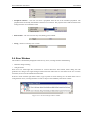
2.4. Error Window
This window is automatically displayed if there are any errors, warnings and hints found during:
• automatic design checking
• code generation
Some errors are found right after inconsistent or incorrect data have been entered, others during the code
generation of a design. The single messages mention the bean where the error was found. If an error concerns
two beans, the error will be attributed to both beans.
If the user clicks with the right mouse button, a pop-up menu is shown allowing user to delete either tools or
code generation errors, warnings and hints in order to improve the readability of the Error window.
Figure 2.15 - Processor Expert Error window
- 14 -
Device Initialization User Manual
User Interface
Pop-up Menu
The pop-up menu invoked by the right mouse button click contains the following items:
• Delete All Tool Errors, Warnings and Hits - removes all tool errors, warnings and hints listed in the error
window
• Delete All code generation errors, warnings and Hints - removes all code generation errors, warnings and
hits listed in the Error window
• Copy to Clipboard - copies the whole content of the window as a text to the clipboard.
Note: This command can be very useful in the case of contacting our support personnel with a bean setup
issue.
• Help - display documentation
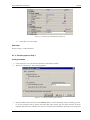
2.5. Options
This dialog window can be invoked before each code generation or using the Options command from the main
menu. The user can specify the options influencing the format and placement of the generated code. Options are
divided into two groups using a tabs.
Basic Options
This offers the following options and option groups:
• Generated file types available:
(for more information on generated files please see the chapter 3.2 Code Generation And Usage)
Relocatable Assembler - generates the relocatable code in the assembly language. This option is not
available for absolute assembly project.
Absolute Assembler - generates an absolute code in assembly language. This option is supported only if
it was selected in the CodeWarrior Project Wizard.
C - generates the code in the C language. This option is not available for the assembly projects.
• After Generation
Save and add files to the project - The files produced by Processor Expert will be named using the
value of 'Generated Module Name' field. The files will be automatically added to the Generated Code
folder to the Code Warrior project.
Create file and do not add to project - the code will be generated into the newly created untitled editor
files.
- 15 -
Device Initialization User Manual
User Interface
Advanced Options
The following options modify the generation of code:
• Generate register modification only if initialization value does not match reset state - This option does
not affect the registers writable only once (for example CONFIGx) nor the registers placed in FLASH (for
example MORx).
• Generate comments about register modification - Source code will contain comments with descriptions of
the registers values.
• Generate interrupt vector table - interrupt vector table content will be generated to the output file.
• Generate interrupt service routine templates - the tool will generate an empty interrupt routines
definitions for all enabled interrupts according to the beans parameters. See chapter 3.4 Defining Interrupt
Service Routines for details.
• Generate initialization of registers writable only once (for example CONFIGx) - These registers can be
written only once after reset due to technological or safety reasons. This options enables the generation of
initialization code for these registers.
• Generate initialization of register placed in FLASH (for example MORx) - Initialization of these
registers will be done during the programming of the application code to the FLASH memory.
• After code generation show description how to use the generated files - If this option is enabled, a dialog
with the short description of the generated modules and their usage is displayed after every code generation.
Common Options
• Show this dialog every time before code generation - using this check-box, the user can enable/disable
appearance of this dialog before every code generation.
- 16 -
Device Initialization User Manual
Using The Tool
3. Using The Tool
The sub-chapters describe basic principles and tasks related to device initialization.
• Peripheral Initialization Beans
• Code Generation And Usage
• Saving And Restoring The Design
• Defining Interrupt Service Routines
• Changing The CPU
• Converting Code Warrior Project To Use The Device Initialization
• Converting Device Initialization Project To Processor Expert
3.1. Peripheral Initialization Beans
A Peripheral Initialization Bean is an object that provides a human-readable interface to initialization parameters
of a selected on-chip CPU peripheral. Parameters of the Peripheral Initialization Bean represent the settings of
all peripheral registers in the clear tabular form. Names of the Peripheral Initialization Beans are
Init_<peripheral> and they are specific for each CPU family.
Adding a Bean
Beans can be added to the design using the Device Initialization window. Click on the unallocated peripheral to
add a new bean. The new bean will be preset to work with the selected device. Inspector dialog will appear
allowing the user to configure parameters of the bean.
Bean Parameters And Device Registers
Every bean contains a group of parameters (properties) that describe the desired initialization state of the device.
These parameters are automatically transformed to values of control registers related to the selected peripheral.
Inspector shows both - bean parameters and resulting registers values.
Bean parameters are grouped to several groups by type. The following groups are commonly present in
peripheral initialization beans:
• Settings - common peripheral parameters
• Pins - configuration of the pins related to the peripheral.
• Interrupts - configuration of the interrupts and interrupt service routines related to the peripheral. See
chapter 3.4 Defining Interrupt Service Routines for details.
• Initialization - parameters related to the peripheral initialization.
CPU beans
A CPU bean is the bean that configures the parameters of the CPU core (like clock source and frequency,
power-saving capabilities etc...). The CPU bean is always present in design and cannot be removed. CPU bean
contains the following parameter groups:
• Clock Settings - configuration of the CPU timing
• Internal Peripherals - configurations of the peripherals not supported by separate beans and settings that
can be shared among beans.
- 17 -
Device Initialization User Manual
Using The Tool
• CPU Interrupts - configuration of the interrupts related to the CPU core.
Modifying Beans Settings
Parameters of existing beans can be configured via the Inspector dialog which can be opened using the Device
Initialization window by clicking on the bean's icon.
3.2. Code Generation And Usage
Starting The Code Generation
Use the Generate Code button in the Device Initialization window or the Generate Code {design name}
command from the main menu.
The Options dialog with the code generation options appears (if it is not disabled by the 'Show this dialog every
time before code generation' check-box). See chapter 3.2 Code Generation And Usage for details.
After confirming the Options dialog by pressing the Generate button, the source code initializing the CPU
registers according to the specified bean parameters is generated.
After a successful code generation, the dialog window appears with a basic information on generated code and
its usage. This dialog window can be enabled/disabled within the Options dialog. See chapter 2.5 Options for
details.
Generated Code
During the Code Generation process the Device Initialization tool generates the initialization code for CPU
peripherals allocated by beans. The generated code reflects the configuration of beans' parameters and is
contained in the function named MCU_init. The user shall call this function at the start of application code to
initialize peripherals.
On ColdFireV1 MCUs, there is additionally generated a function named __initialize_hardware which contains
settings of the clock source and settings of core registers and system control registers (SOPTx, SPMSCx, all
write-once registers). This function is called from the after-reset startup code.
The generated module consists of two files:
• Implementation file containing the code of the initialization function(s) and optionally the interrupt vectors
table.
• Interface file containing the declarations which can be referenced by the user. This file is generated only if
the files are stored to a disc (see below).
Depending on the After generation option, the files can be stored to a disk and added to the current project or just
shown in the editor as untitled files. See chapter 2.5 Options for details.
Device Initialization tool can generate the following types of initialization code:
• Relocatable Assembler - The implementation file has the extension .asm and the interface file has the
extension .inc. This option is not available for absolute assembly projects.
• Absolute Assembler - The implementation file has the extension .inc and must be included at the end of the
user module, where address for code is selected (using ORG). Absolute assembler is supported only if it was
selected in the CodeWarrior Project Wizard.
- 18 -
Device Initialization User Manual
Using The Tool
• C language - The implementation file has the extension .c and the interface file has the extension .h.
A default name for the generated module is 'MCUInit'. An Initialization code format, the generated module name
(and other code generation options) can be configured in the Options dialog. See chapter 2.5 Options for details.
User Changes In The Generated Code
If the content of generated modules is written to the disk, it always overwrites the existing files during every
code generation, which discards all user modification with the exceptions of:
• user definitions (or any generally any other source code) in .C (or .asm) placed in the special comment
marks. In case of C language it looks like:
/* User declarations and definitions */
User source code...
/* End of user declarations and definitions */
• content of interrupt service routines that are assigned to any interrupt(s) in the peripheral initialization beans.
See chapter 3.4 Defining Interrupt Service Routines for details.
• unused interrupt service routines (no bean contains their name). They do not disappear but they are moved to
the end of the file. The generated comments before and after the ISR must not be modified for this feature to
work properly.
Notice: No user changes in the .h (or .inc in case of assembly language) are preserved. The file is always
overwritten.
Using The MCU_init Function
To call MCU_init function from the main file, the user should do the following modification into his/her code:
• Device initialization by default generates an interrupt vectors table containing all interrupt vectors (it can be
disabled in the Options dialog, see chapter 2.5 Options for details). Existing interrupt vector definitions have
to be removed or commented out to avoid a conflict.
For details on configuring interrupt vectors in Device Initialization please see the chapter 3.4 Defining
Interrupt Service Routines.
• Add a calling of the generated MCU_init function at the beginning of the application main routine (newly
created projects already contain this line). Note: The prototype/external declaration of the MCU_init function
or a command including the interface file with this declaration has to be present in the module where the
MCU_init is called. In a new project it is already prepared in the main file.
For step-by-step instructions on how to convert the existing C or assembly project to use the DeviceInitialization
please see the chapter 3.6 Converting Code Warrior Project To Use The Device Initialization.
- 19 -
Device Initialization User Manual
Using The Tool
3.3. Saving And Restoring The Design
Automatic Saving
All parameters and settings of the device initialization design are stored in the file with the extension .iPE and
the same name as the CodeWarrior project file. It is also located within the same directory.
The design is saved after each successful code generation with the option Save and add files to project, so it
reflects the state of the code in the generated modules.
The design is automatically loaded when the project created with the Device Initialization option is opened.
Numbered Archive Files
When the design is automatically saved, the previous content of the saved file is not overwritten. It is renamed to
a new name with the number appended to the end and stored in the same directory. This number is automatically
incremented after every save. Previous design versions data, stored in numbered files, can be manually restored
using a manual restore function (see the following paragraph for details).
Manual Backup And Restore
The user can manually save/restore all settings to/from a .iPE file on the disk. This file can be used in another
project, archived or for example sent by e-mail.
Use the Backup/Restore buttons from the Device Initialization Window or use the main menu commands
Backup Device Settings... and Restore Device Settings.... The restored settings override all current settings they are lost. The user is warned about it and has to confirm the restoration process. See chapters 2.2 Device
Initialization Window and 2.1 Main Menu for details.
Closing Device Initialization Window
After closing the Device Initialization window, in case there are any changes in the design or the code has not
been generated yet, a dialog offering design save will appear. If the user confirms this dialog, the file name
selection dialog appears allowing the user to choose a name for the file.
3.4. Defining Interrupt Service Routines
Some Peripheral Initialization beans allow the initialization of an interrupt service routine. Interrupt(s) can be
enabled in initialization code using appropriate parameters that can be usually found within a group Interrupts.
After enabling, the specification of an Interrupt Service Routine (ISR) name using the ISR name property is
required. This name is generated to Interrupt Vector table during the code generation process. See chapter 3.2
Code Generation And Usage for details.
Please notice that if the ISR name is filled it is generated into the Interrupt Vector Table even if the interrupt
property is disabled.
- 20 -
Device Initialization User Manual
Using The Tool
Figure 3.1 - Example Of The Interrupt Setup
Enabling/disabling peripheral interrupts during runtime has to be done by the user's code.
Interrupt Service Routines Code
The ISR with the specified name has to be declared according to the compiler conventions and fully
implemented by the user. Declarations of the ISRs that do not exist yet can be generated automatically during the
code generation process into the generated module if the option Generate interrupt service routine templates
is enabled. See chapter 2.5 Options for details.
The contents of interrupt service routines, written by the user, that are assigned to any interrupt within
beans' parameters is protected against being overwritten during the code Generation process. In case the
interrupt service routine is not assigned to any interrupt, it's moved to the end of the file.
Warning: The user is responsible for synchronizing ISR names in the code and ISR names specified in beans. If
an ISR is renamed, the name has to be changed in the bean(s) where this ISR name is assigned and vice versa.
This has to be done before next code generation. Otherwise the newly specified ISR won't be found and the
existing ISR with an old name will be treated as unassigned - it will be moved to the end of file.
3.5. Changing The CPU
Changing CPU package
The type of the CPU package can be changed using the Select CPU Package button in the Device Initialization
window. See chapter 2.2 Device Initialization Window for details.
Switching The Project To a Different CPU Derivative
Different MCU derivative can be selected using the CodeWarrior menu command Project | Change MCU /
Connection
Beans Assignment
If some peripherals of the MCU set by beans are not supported by the new MCU derivative the project is
switched to, the dialog window with a list of the unsupported items is shown. The user is asked to confirm that
these items will be removed from the design.
- 21 -
Device Initialization User Manual
Using The Tool
3.6. Converting Code Warrior Project To Use The Device
Initialization
This chapter guides the user through a conversion from a plain C or assembly project to the project using the
Device Initialization plugin and a peripheral initialization code generated by this tool.
The following steps should be done to convert the project:
1.
Open the project you want to convert.
2.
Select the Device Initialization | Initialize Device main menu command. Confirm the dialog window
with the question 'Do you want to add a new iPE device setting?' by clicking the 'Yes' button.
A Device Initialization window with a CPU package appears.
3.
Configure the peripherals and generate the initialization code by using the Generate code button. See
chapters 3.1 Peripheral Initialization Beans and 3.2 Code Generation And Usage for details.
4.
Open and modify the main file of the project to reference and call the MCU_init subroutine the following
way:
(This subroutine will contain an initialization code generated according to the peripheral configuration
after the 'Generate code' button is pressed. See chapter 3.2 Code Generation And Usage for details.)
For Relocatable Assembly Project :
Find the part of the code including the derivative information and add the bold marked line:
; Include derivative-specific definitions
INCLUDE 'derivative.inc'
XREF MCU_init
Then find the main routine start and add the MCU_init call at the place you want the peripherals to be
initialized :
; code section
MyCode:
SECTION
main:
_Startup:
...
; Call generated Device Initialization function
JSR
MCU_init
For Absolute Assembly Project :
Find the part of the code including the derivative information and add the bold marked line:
; Include derivative-specific definitions
INCLUDE 'derivative.inc'
INCLUDE 'MCUInit.inc'
Then find the main routine start and add the MCU_init call at the place you want the peripherals to be
initialized :
_Startup:
...
; Call generated Device Initialization function
JSR
MCU_init
- 22 -
Device Initialization User Manual
Using The Tool
For C Project :
Add the MCU_init function declaration and its call to the main C module by adding the bold marked
lines into the code:
void MCU_init(void); /* Device init function declaration */
...
void main(void) {
MCU_init(); /* call Device Initialization */
...
5.
Remove, comment or modify the existing code that conflicts with the generated initialization code.
Note: The Device Initialization generates the complete interrupt vector table. Any interrupt declarations in
the .prm file (lines starting with vector keyword) or elsewhere need to be removed or commented out and
all interrupt need to be configured by using the Device initialization. Please see the chapter 3.4 Defining
Interrupt Service Routines for details.
6.
Build the application. The peripheral initialization code can be anytime re-generated by using the
Generate Code button.
3.7. Converting Device Initialization Project To Processor Expert
The project created using the Device Initialization can be converted to Processor Expert. This is useful when the
user finds out that he/she would like to use additional features of Processor Expert. Please see the chapter 1.4
Rapid Application Development Tools for the tools comparison. This conversion is available for C projects only.
Warning: Don't forget to backup the whole project before the conversion. Some files will have to be removed
from the project. The conversion to Processor Expert is recommended to experienced users only.
Conversion Steps
1.
Generate code to save the last state of the design (if you haven't already done it).
2.
Backup the whole project.
3.
Select the menu command Processor Expert | Open
4.
Switch to Files tab of the CodeWarrior project panel.
5.
Remove the following files from the project using the DEL key or the Remove pop-up menu command:
Sources / main.c (It will be replaced by the {projectname}.c)
Include / derivative.h (It will be replaced by the generated IO_Map.h)
Include / <CPUderivative>.h (It will be replaced by the generated IO_Map.h)
Linker Files / Project.prm (It will be replaced by the generated {projectname}.prm)
Libs / <CPUderivative>.C (It will be replaced by the generated IO_Map.h)
6.
Remove all object code using the menu command Project | Remove object code....
7.
Generate the code with the command Processor Expert | Generate Code <projectname>
8.
Copy the user code from the function in main.c into the newly generated main module <projectname>.c at
the place marked with the text /* Write your code here */.
9.
Copy the user ISRs code from the in MCUinit.c (or a filename specified in options.) into a new user
module or to the main module.
10. Make the project using the Project Make command.
- 23 -
Device Initialization User Manual
Tutorials
4. Tutorials
The following tutorials are available:
• Tutorial Project 1 - Blinking LED In C
• Tutorial Project 2 - Blinking LED In Assembly
4.1. Tutorial Project 1 - Blinking LED In C
This simple tutorial describes a periodically blinking LED project in the C language. An LED is connected to
one pin of the CPU and the port output is controlled in the timer overflow interrupt routine.
How it works
The project uses a LED connected to the pin 0 of the PTF port of the MC9S08GB60 CPU. TPM1 Timer
overflow is used to generate the periodical interrupt. The state of the port is changed in the timer overflow
interrupt routine.
Required Hardware Setup
The project is designed for Freescale evaluation board M68DEMO908BG60 with MC9S09BG60 CPU in a
default setup. No additional settings are required.
Animated tutorial
This tutorial is also available in a version showing each step as an animation. To start the animated tutorial open
the CodeWarrior start-up dialog (using the menu command File | Startup dialog ) and click the button Run
Getting Started Tutorial. Then follow the C with Device Initialization Tutorial link.
Steps
1.
Creating a new project
2.
Configuring Peripherals
3.
Code generation
4.
Writing user code
- 24 -
Device Initialization User Manual
Tutorials
4.1.1. Tutorial project1, Step 1
Creating a New Project
1.
Start the CodeWarrior or open the Startup dialog by selecting the menu command File | Startup dialog.
2.
Click on the button Create New Project in the startup dialog.
3.
The HC(S)08 New Project wizard is invoked
4.
a.
Select the MC9S08GB60 CPU derivative (under the HCS08 / HCS08G Family) and choose your
debugging connection (for example P&E Multilink). Click Next.
b.
Ensure the 'C' language check-box is set and type the project name: 'LED1C'. Click Next.
c.
Skip external files addition by clicking on the Next button.
d.
Choose the Device Initialization in Rapid Application Development Options. and click the Finish
button.
A new project is created.
Figure 4.1 - CodeWarrior IDE after creating the new project
Next step
Follow to Step 2 - Configuring the peripherals.
- 25 -
Device Initialization User Manual
Tutorials
4.1.2. Tutorial project1, Step 2
Configuring Peripherals
1.
Output pin configuration
a.
Click on the PTF peripheral field in the package diagram within the Device Initialization window.
b.
Unfold the Settings group in the Bean parameters panel and change the Port control parameter to
Individual pins (using the round button ).
c.
In the Pins group enable the Pin0.
d.
Change the Direction parameter in the Pin0 group to Output.
Figure 4.2 - Port PTF initialization parameters
e.
2.
Click on the OK button to save the peripheral initialization.
Timer configuration: (The timer shall be set to overflow with period of about 0.5s to generate the
periodical interrupt)
a.
Click on the TPM1 peripheral.
b.
Unfold the Settings group.
c.
Set the Clock source select parameter to Bus rate clock.
d.
Select the value 32 for Prescaler parameter. (The information field with period should show
524.296ms.)
e.
Unfold the Interrupts group.
f.
Set the Overflow Interrupt to Enable.
g.
Type the LEDtimer to the ISR Name parameter.
- 26 -
Device Initialization User Manual
Tutorials
Figure 4.3 - TPM1 timer initialization parameters.
h.
Click OK to save the settings.
Next step
Follow to Step 3 - Code Generation.
4.1.3. Tutorial project1, Step 3
Code generation
1.
Click on the Generate Code button in the Device Initialization window.
2.
The Device initialization - Options dialog appears.
Figure 4.4 - Code generation options dialog
3.
Keep the default values and click on the Generate button. Confirm the dialog window informing you how
to use the generated code by clicking the 'OK' button (this window may not appear because of beeing
disabled). The MCUinit.h and MCUinit.c files are now generated and added to the project (into the project
- 27 -
Device Initialization User Manual
Tutorials
panel files tab folder Generated Code).
Next step
Follow to Step 4 - Writing User Code.
4.1.4. Tutorial project1, Step 4
Writing User Code
1.
Open the MCUinit.c file in the editor if it's not already opened.
2.
Find the code of the generated interrupt service routine (ISR):
__interrupt void LEDtimer(void)
{
/* Write your interrupt code here ... */
}
3.
Replace the text /* Write your interrupt code here ... */ with the following code marked bold:
__interrupt void LEDtimer(void)
{
PTFD_PTFD0 = ~PTFD_PTFD0;
// invert the output values
TPM1SC;
// read the timer overflow status
TPM1SC_TOF = 0; // and clear it
}
Next step
Follow to Step 5 - Running The Project.
4.1.5. Tutorial project1, Step 5
Running The Project
1.
Make the project using the menu command Project | Make . You can ignore the compiler warning
message.
2.
Run the project using the command Project | Debug or using the debug icon.
3.
After executing the code, the LED should blink with period of about 0.5s.
- 28 -
Device Initialization User Manual
Tutorials
4.2. Tutorial Project 2 - Blinking LED In Assembly
This simple tutorial describes a periodically blinking LED project. An LED is connected to ne pin of the CPU
and the port output is controlled in the timer overflow interrupt routine. The functionality of this project is the
same as the Tutorial 1 except the implementation is done in assembly language.
How it works
The project uses a LED connected to the pin 0 of the PTF port of the MC9S08GB60 CPU. TPM1 Timer
overflow is used to generate the periodical interrupt. The state of the port is changed in the timer overflow
interrupt routine.
Required Hardware Setup
The project is designed for Freescale evaluation board M68DEMO908BG60 with MC9S09BG60 CPU in the
default setup. No additional settings are required.
Animated tutorial
This tutorial is also available in a version showing each step as an animation. To start the animated tutorial open
the CodeWarrior start-up dialog (using the menu command File | Startup dialog ) and click the button Run
Getting Started Tutorial. Then select the Relocatable Assembly with Device Initialization Tutorial link.
Steps
1.
Creating a new project
2.
Configuring Peripherals
3.
Code generation
4.
Writing user code
4.2.1. Tutorial project 2, Step 1
Creating a New Project
1.
Start the CodeWarrior
2.
Click on the button Create New Project in the startup dialog.
3.
The HC(S)08 New Project wizard is invoked
4.
a.
Select the MC9S08GB60 CPU derivative (under the HCS08 / HCS08G Family). Choose your
debugging connection (for example P&E Multilink). Click Next.
b.
Select the ' Relocatable Assembly ' language check-box and unselect the ' C ' language. Write the
project name: 'LED2asm'. Click Next.
c.
Skip external files addition by clicking the Next button.
d.
Choose Device Initialization in Rapid Application Development Options.
e.
Click the Finish button.
A new project is created.
- 29 -
Device Initialization User Manual
Tutorials
Figure 4.5 - CodeWarrior IDE after creating the new project
Next step
Follow to Step 2 - Configuring the peripherals.
4.2.2. Tutorial project 2, Step 2
Configuring Peripherals
1.
Output pin configuration
a.
Click on the PTF peripheral field in the package diagram within the Device Initialization window.
b.
Unfold the Settings group in the Bean parameters panel and change the Port control parameter to
Individual pins (using the round button ).
c.
In the Pins group enable the Pin0.
d.
Change the Direction parameter in the Pin0 group to Output.
- 30 -
Device Initialization User Manual
Tutorials
Figure 4.6 - Port PTF initialization parameters
e.
2.
Click on the OK button to save the peripheral initialization.
Timer configuration: (The timer shall be set to overflow with period of about 0.5s to generate the
periodical interrupt)
a.
Click on the TPM1 peripheral.
b.
Unfold the Settings group.
c.
Set the Clock source select parameter to Bus rate clock.
d.
Select the value 32 for Prescaler parameter. (The information field with period should show
524.296ms.)
e.
Unfold the Interrupts group.
f.
Set the Overflow Interrupt to Enable.
g.
Type the LEDtimer to the ISR Name parameter.
Figure 4.7 - TPM1 timer initialization parameters.
h.
Click OK to save the settings.
Next step
Follow to Step 3 - Code Generation.
- 31 -
Device Initialization User Manual
Tutorials
4.2.3. Tutorial project 2, Step 3
Code generation
1.
Click on the Generate Code button in the Device Initialization window.
2.
The Device initialization - Options dialog appears.
Figure 4.8 - Code generation options dialog
3.
Keep the default values and click on the Generate button. Confirm the dialog window inroming you how
to use the generated code by clicking the 'OK' button (this window may not appear because of beeing
disabled). The MCUinit.inc and MCUinit.asm files are generated and added to the project (into the project
panel files tab folder Generated Code).
Next step
Follow to Step 4 - Writing User Code.
4.2.4. Tutorial project 2, Step 4
Writing User Code
1.
Open the MCUinit.asm file in the editor (if it isn't already open).
2.
Find the code of the generated interrupt service routine (ISR) and replace the text /* Write your interrupt
code here ... */ by the code marked bold.
;** ===================================================================
;**
Interrupt handler : LEDtimer
;**
;**
Description :
;**
User interrupt service routine.
;**
Parameters : None
;**
Returns
: Nothing
;** ===================================================================
- 32 -
Device Initialization User Manual
Tutorials
XDEF
LEDtimer
LEDtimer:
; Write your interrupt code here ...
LDA
#$01
; Mask for bit 1
EOR
PTFD
; Invert the first bit of PTFD
STA
PTFD
; Write the result to PTFD
LDA
BCLR
TPM1SC
TPM1SC_TOF,TPM1SC
; Read the register
; and clear the timer overflow flag
RTI
; end of LEDtimer
Next step
Follow to Step 5 - Running The Project.
4.2.5. Tutorial project 2, Step 5
Running The Project
1.
Make the project using the menu command Project | Make
2.
Run the project using the command Project | Debug or using the debug icon.
3.
After executing the code, the LED should blink with period of about 0.5s.
- 33 -
Device Initialization User Manual
Index
5. Help Revisions History
The current revision number: 1.8 (Generated: 10.8.2007 14:58:08)
10.08.2007 Revision 1.8
• Added __initialize_hardware function description
26.07.2007 Revision 1.7
• Changed handling of ISRs contend during generation
07.03.2007 Revision 1.6
• Initial addition of ColdFire V1
12.09.2006 Revision 1.5
• Updated Tutorials, Quick start and Code Genaration and usage to match the project wizard in CodeWarrior
for HC(S)08 V5.1.
• Removed animated tutorials - replaced by links to the same tutorials available from startup dialog.
• Added a new chapter 'Converting project to use the Device Initialization'.
27.04.2006 Revision 1.4
• Added information on Initialization Value meaning.
• Added information on Absolute/relative assembly options.
21.11.2005 Revision 1.3
• Tutorials updated.
• Added animated versions of tutorials.
• The Quick Start and Code Generation chapter updated.
7.11.2005 Revision 1.2
• Corrected error in the CPU derivative name in tutorials
1.11.2005 Revision 1.1
• Languace corrections
• Updated the Options, Tutorial and PE conversion chapters.
26.10.2005 Revision 1.0
• Initial release.
- 34 -
Device Initialization User Manual
Index
INDEX
Adding Device Initialization
Bean
Changing CPU
Code generation
Configuring peripherals
Converting project
Converting to Processor Expert
CPU bean
Creating ISRs
Design
Design steps
Features
Initialization code
Inspector
Inspector items
Internal peripherals
Interrupt initialization
ISRS
Main Menu
Module
New project
Options
Peripheral Initialization
Peripheral settings
Porperty types
Project creation
Properties
RAD tools
Saving settings
Settings backup
Target CPU
Tools comparison
Tutorial 1
Tutorial 2
Using generated code
22
3, 17
21
18, 32, 27
30, 26
22
23
3
20
3
4
3
18
11, 3
13
3
20
20
7
3
25, 29
15
17
3
13
4
3
5
20
20
4
5
24
29
18
- 35 -
Device Initialization User Manual
Index
- 36 -