1
ISEP
Polytechnic Institute of Porto
School of Engineering
Multiprocessor platform using LEON3
processor
António João dos Santos Sousa
A dissertation submitted in partial fulfilment of the specified requirements for the degree
of Master in Electrical and Computer Engineering
Supervision: Prof. Eduardo Silva and Prof. Alfredo Martins
Enterprise orientation: Eng. Rodolfo Martins from Evoleo Technologies
Porto, December, 2009
Abstract
The recent advances in embedded systems world, lead us to more complex systems with
application specific blocks (IP cores), the System on Chip (SoC) devices. A good example
of these complex devices can be encountered in the cell phones that can have image processing cores, communication cores, memory card cores, and others.
The need of augmenting systems’ processing performance with lowest power, leads to a
concept of Multiprocessor System on Chip (MSoC) in which the execution of multiple
tasks can be distributed along various processors.
This thesis intends to address the creation of a synthesizable multiprocessing system to be
placed in a FPGA device, providing a good flexibility to tailor the system to a specific application. To deliver a multiprocessing system, will be used the synthesisable 32-bit
SPARC V8 compliant, LEON3 processor.
Keywords
Multiprocessor, Multicore, LEON3, IP core, SPARC V8, FPGA, Altera, SoC, MSoC,
Linux, Operating System.
iii
iv
Resumo
Os avanços recentes no mundo dos sistemas embebidos levam-nos a sistemas mais
complexos com blocos para aplicações específicas (IP cores), os dispositivos System on
Chip (SoC). Um bom exemplo destes complexos dispositivos pode ser encontrado nos
telemóveis, que podem conter cores de processamento de imagem, cores de comunicações,
cores para cartões de memória, entre outros.
A necessidade de aumentar o desempenho dos sistemas de processamento com o menor
consumo possível, leva ao conceito de Multiprocessor System on Chip (MSoC) em que a
execução de múltiplas tarefas pode ser distribuída por vários processadores.
Esta Tese pretende abordar a criação de um sistema de multiprocessamento sintetizável
para ser colocado numa FPGA, proporcionando uma boa flexibilidade para a adaptação do
sistema a uma aplicação específica. Para obter o sistema multiprocessamento, irá ser
utilizado o processador sintetizável SPARC V8 de 32-bit, LEON3.
Palavras-Chave
Multiprocessador, Multicore, LEON3, IP core, SPARC V8, FPGA, Altera, SoC, MSoC,
Linux, Sistema Operativo.
v
vi
Table of Contents
ABSTRACT ...................................................................................................................................................III
RESUMO .........................................................................................................................................................V
TABLE OF CONTENTS .............................................................................................................................VII
LIST OF FIGURES....................................................................................................................................... IX
LIST OF TABLES......................................................................................................................................... XI
LIST OF ACRONYMS.............................................................................................................................. XIII
1.
2.
3.
4.
5.
GENERAL INFORMATION................................................................................................................ 1
1.1.
INTRODUCTION ................................................................................................................................. 1
1.2.
CONTEXT .......................................................................................................................................... 3
1.3.
OBJECTIVES ...................................................................................................................................... 3
1.4.
STRUCTURE OF THIS THESIS.............................................................................................................. 4
MULTIPROCESSOR CONCEPTS...................................................................................................... 7
2.1.
HOMOGENEOUS AND HETEROGENEOUS SYSTEMS ............................................................................ 7
2.2.
SYMMETRIC MULTIPROCESSING AND ASYMMETRIC MULTIPROCESSING .......................................... 9
2.3.
CACHE COHERENCY PROTOCOL ..................................................................................................... 10
2.4.
MEMORY MANAGEMENT UNIT ....................................................................................................... 11
FPGA ARCHITECTURE AND HARDWARE DESCRIPTION LANGUAGE............................. 13
3.1.
FPGA ARCHITECTURE OVERVIEW ................................................................................................. 13
3.2.
ALTERA CYCLONE III ..................................................................................................................... 15
3.3.
VHDL ............................................................................................................................................ 17
PROCESSORS ARCHITECTURES .................................................................................................. 21
4.1.
ERC32............................................................................................................................................ 21
4.2.
LEON............................................................................................................................................. 23
4.3.
ARM .............................................................................................................................................. 24
LEON3 ARCHITECTURE ................................................................................................................. 27
5.1.
PROCESSOR..................................................................................................................................... 27
5.2.
INTEGER UNIT ................................................................................................................................ 28
5.3.
DEBUG SUPPORT UNIT 3 ................................................................................................................. 30
5.4.
INTERCONNECT BUS (AMBA)........................................................................................................ 30
vii
5.5.
CACHES ...........................................................................................................................................32
5.6.
MULTIPROCESSOR SUPPORT ............................................................................................................32
6.
SYSTEM REQUIREMENTS AND SPECIFICATION.....................................................................35
6.1.
GENERAL REQUIREMENTS ...............................................................................................................35
6.2.
SYSTEM SPECIFICATION ..................................................................................................................36
6.3.
SELECTED HARDWARE FRAMEWORK ..............................................................................................37
7.
PRELIMINARY ARCHITECTURE DESIGN ..................................................................................41
7.1.
PRELIMINARY DESIGN .....................................................................................................................41
7.2.
VERIFICATION AND TEST CONFIGURATIONS ...................................................................................45
8.
DETAILED ARCHITECTURE DESIGN ..........................................................................................49
8.1.
SYSTEM CONFIGURATION................................................................................................................51
8.2.
PIN ASSIGNMENT .............................................................................................................................51
8.3.
PRE-SYNTHESIS SIMULATION ..........................................................................................................51
8.4.
SYNTHESIS AND PLACE AND ROUTE ................................................................................................52
9.
VERIFICATION AND OVERALL TESTS .......................................................................................53
9.1.
HARDWARE VERIFICATION .............................................................................................................53
9.2.
TEST RESULTS .................................................................................................................................54
9.3.
CONCLUDING REMARKS ..................................................................................................................61
10.
GENERAL CONCLUSIONS...........................................................................................................63
10.1.
CONCLUSIONS .................................................................................................................................63
10.2.
FUTURE WORK ................................................................................................................................64
REFERENCES...............................................................................................................................................67
APPENDIX A. GRLIB IP LIBRARY ..........................................................................................................71
APPENDIX B. MEMORY MAP AND INTERRUPTS ..............................................................................77
APPENDIX C. EXTERNAL INTERFACE SIGNALS ..............................................................................79
APPENDIX D. PIN ASSIGNMENT.............................................................................................................81
viii
List of Figures
Figure 1
C6474 family – homogeneous multicore system [10].................................................... 8
Figure 2
Cell processor – heterogeneous multicore system [12].................................................. 8
Figure 3
Symmetric Multiprocessing and Asymmetric Multiprocessing [15]. ............................ 9
Figure 4
Cache replicas in multiple processors, a coherency problem in SMP systems [18]. ... 10
Figure 5
Block diagram representation of a system with MMU [5]........................................... 11
Figure 6
Paging concept [4]........................................................................................................ 12
Figure 7
Segmentation concept [4]............................................................................................. 12
Figure 8
LEON3 cache and MMU perspective [3]..................................................................... 12
Figure 9
FPGA architecture........................................................................................................ 14
Figure 10
Current FPGA architecture........................................................................................... 15
Figure 11
Altera Cyclone III architecture overview..................................................................... 16
Figure 12
Multiplier block architecture ........................................................................................ 17
Figure 13
VHDL AND gate block diagram representation.......................................................... 19
Figure 14
ESA / ERC32 evaluation board Error! Reference source not found.. .......................... 21
Figure 15
ERC32 architecture Error! Reference source not found............................................... 22
Figure 16
TSC695F block diagram [23]....................................................................................... 23
Figure 17
LEON block diagram Error! Reference source not found............................................ 24
Figure 18
S5PC100 from ARM Cortex A8 family used in new iPhone 3G [33]. ........................ 25
Figure 19
ARM11 MPCore architecture ...................................................................................... 26
Figure 20
Harvard architecture [1] ............................................................................................... 28
Figure 21
LEON3 integer unit data path diagram [3]................................................................... 29
Figure 22
DSU and debug interface [2]........................................................................................ 30
Figure 23
AHB multiplexer interconnection [6]........................................................................... 31
Figure 24
Typical AMBA AHB and APB system [6] .................................................................. 32
Figure 25
LEON3-MP system perspective................................................................................... 36
Figure 26
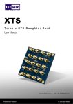
Cyclone III FPGA Starter Kit....................................................................................... 38
Figure 27
Final hardware framework ........................................................................................... 39
Figure 28
Proposed multiprocessor architecture .......................................................................... 42
Figure 29
LEON3 processor internal architecture........................................................................ 43
Figure 30
LEON3 DSU interfaces................................................................................................ 44
ix
Figure 31
LEON3 multiprocessor design perspective .................................................................. 45
Figure 32
LEON3 multiprocessor platform.................................................................................. 49
Figure 33
Design flow perspective ............................................................................................... 50
Figure 34
P1 benchmark time consumption over time ................................................................. 55
Figure 35
P2 benchmark time consumption over time ................................................................. 56
Figure 36
R1 benchmark time consumption over time................................................................. 57
Figure 37
R2 benchmark time consumption over time................................................................. 58
Figure 38
M1 benchmark time consumption over time................................................................ 59
Figure 39
M2 benchmark time consumption over time................................................................ 60
x
List of Tables
Table 1
Hardware configurations description ........................................................................... 46
Table 2
Benchmark applications description ............................................................................ 47
Table 3
P1 benchmark results ................................................................................................... 55
Table 4
P2 benchmark results ................................................................................................... 56
Table 5
R1 benchmark results ................................................................................................... 57
Table 6
R2 benchmark results ................................................................................................... 58
Table 7
M1 benchmark results .................................................................................................. 59
Table 8
M2 benchmark results .................................................................................................. 60
Table 9
Benchmark results summary ........................................................................................ 61
Table 10
Processors and support functions ................................................................................. 71
Table 11
Floating-point units ...................................................................................................... 71
Table 12
Memory controllers ...................................................................................................... 72
Table 13
AMBA Bus control ...................................................................................................... 72
Table 14
PCI interface................................................................................................................. 73
Table 15
On-chip memory functions........................................................................................... 73
Table 16
Serial communication................................................................................................... 73
Table 17
Ethernet interface ......................................................................................................... 74
Table 18
USB interface ............................................................................................................... 74
Table 19
MIL-STD-1553 Bus interface ...................................................................................... 74
Table 20
Encryption .................................................................................................................... 74
Table 21
Simulation and debugging............................................................................................ 74
Table 22
CCSDS Telecommand and telemetry functions........................................................... 75
Table 23
HAPS functions............................................................................................................ 75
Table 24
AMBA address range and interrupts ............................................................................ 77
Table 25
External interface signals list ....................................................................................... 79
Table 26
Pin assignment list........................................................................................................ 81
xi
This page was intentionally left blank.
xii
List of Acronyms
AHB
Advanced High-Performance Bus
AMP
Asymmetric Multiprocessing
APB
Advanced Peripheral Bus
ARM
Advanced Risc Machine
ASB
Advanced System Bus
ASIC
Application Specific Integrated Circuit
ASSP
Application Specific Standard Products
ATB
Advanced Test Bus
AXI
Advanced eXtensible Interface
CPLD
Complex Programmable Logic Device
DDR
Double Data Rate
DSU
Debug Support Unit
EDA
Electronic Design Automation
EEPROM
Electrically Erasable Programmable Read-Only Memory
ESA
European Space Agency
ESTEC
European Space Research and Technology Centre
FIFO
Firs-In First-Out
FPGA
Field Programmable Gate Array
FPU
Floating Point Unit
HDL
Hardware Description Language
IC
Integrated Circuit
IEEE
Institute of Electrical and Electronics Engineers
IU
Integer Unit
I/O
Input/Output
JTAG
Joint Test Action Group
JVM
Java Virtual Machine
LUT
Look-Up Table
MEC
Memory Controller
MMU
Memory Management Unit
MSoC
Multiprocessor System On-Chip
xiii
NASA
National Aeronautics and Space Administration
OS
Operating System
PCI
Peripheral Component Interconnect
RAM
Random Access Memory
RISC
Reduced Instruction Set Computer
ROM
Read Only Memory
RTEMS
Real-Time Executive for Multiprocessor Systems
RTOS
Real-Time Operating System
SEL
Single Event Latch-up
SEU
Single Event Upset
SMP
Symmetric Multiprocessing
SoC
System On-Chip
SPARC
Scalable Processor Architecture
SPE
Synergetic Processing Element
SDRAM
Synchronous Dynamic Random Access Memory
SRAM
Synchronous Random Access Memory
UART
Universal Asynchronous Receiver Transmitter
US
United States
USB
Universal Serial Bus
VHDL
VHSIC Hardware Description Language
VHSIC
Very High Speed Integrated Circuit
TLB
Translation Look-aside Buffer
xiv
1.
1.1.
GENERAL INFORMATION
INTRODUCTION
Actual embedded systems have all interfaces needed in one chip, a SoC (System on Chip),
resulting in an expressive reduction in space and costs of a system. The increase of processing needs in actual systems lead us to multiprocessors, each executing dedicated tasks
with high level of processing capabilities improving the overall system performance.
A SoC is intended to implement most or even all functionalities of an electronic system
and can include: a processor to manage the system, on-chip memories and memory controllers to interface external memories, DSP functionalities, specific co-processors, communication peripherals like PCI/PCIe, USB, Ethernet, UART, SPI and I²C, among others.
This type of devices can be found in many product categories like cell phones requiring
low-power programmable processors, telecommunications and networking using several
high-speed and high complex systems SoC and digital televisions with needs of higher
resolution [1].
With the needs of more speed and more processing power to achieve the performance
wanted, concepts of Multiprocessor System-on-Chip (MSoC) appear. The concept is the
same of SoC but with multiple processors.
1
Another important issue related to SoC or MSoC is where to implement it. Such systems
were only developed by Integrated Circuits (ICs) manufacturers using Electronic Design
Automation (EDA) tools for the development of Application Specific Integrated Circuits
(ASICs). With the progressive development of new powerful and feature rich Field Programmable Gate Arrays (FPGAs) and Complex Programmable Logic Device (CPLD), this
type of developments can be done more easily in much less time, taking the advantage of
being configurable, to reduce the overall system space, weight and providing high performance with the lowest power consumption compared with standard ICs, which makes
these devices ideal for high performance embedded systems.
As the systems complexity grows, the management can be also complex in such way that
the use of an Operating System (OS) or a Real Time Operating System (RTOS) is a must.
With the multiprocessing systems appearance, a new type of OS supporting both Symmetric Multiprocessing (SMP) and Asymmetric Multiprocessing (AMP) systems arises.
Nowadays, some areas can benefit from the high performance and low power consumption
provided by this type of system designs. These product design benefits can be encountered
in space, aerospace, military, automotive, medical and autonomous systems areas, where
the system reliability is a major concern.
Today we can found multiprocessor systems in desktops or laptops devices, named dualcore or quad-core, but this type of devices are not suitable for embedded systems or designs with high degree of tailoring. New design tools to build multiprocessor systems for
embedded designs are now accessible, providing support to FPGA devices using Hardware
Description Languages like VHDL or Verilog.
This thesis addresses the creation of a synthesizable multiprocessing system can be placed
in any FPGA device architecture providing flexibility for choosing the right hardware for a
specific application. To deliver a multiprocessing system it will be used the synthesisable
32-bit SPARC V8 compliant, LEON3 processor, which is used in space applications by
Evoleo Technologies, the main requirements supplier in this thesis.
The Linux 2.6 OS which supports SMP, will be used in order to test the system performance and provide base software configured to be used in the developed architecture.
2
1.2.
CONTEXT
This thesis was developed in a cooperation between Evoleo Technologies, Lda and the
Autonomous Systems Laboratory from ISEP.
To augment and expand knowledge in the area of multiprocessing systems for industry and
space applications, this thesis was proposed by Evoleo Technologies, Lda, in the context of
the Master’s course.
Evoleo Technologies, Lda is an enterprise that acts in two main branches. One is oriented
to industry with development of automatic test equipments (ATE), automation solutions
with National Instruments hardware and software (LabView). The second branch is oriented to space applications, with development of hardware and software.
The Autonomous Systems Laboratory is a research and development (R&D) unit from
ISEP, conducting research in autonomous systems and related areas, such as navigation,
control and coordination of multiple robots. Currently, this laboratory is responsible for the
Master’s course in Autonomous Systems, a specialization within the Electrical and Computer Engineering area.
1.3.
OBJECTIVES
The main goal of this thesis is to create a base of knowledge developing synthesisable multiprocessor systems, tailored to a specific design using FPGA devices, delivering the whole
system design tools knowledge for future designs, reducing the time to market of multiprocessor systems designs.
The FPGA family to be used shall be from the Altera manufacturer, benefiting of the
knowledge developed by the enterprise with this manufacturer devices.
The multiprocessor architecture proposed in this thesis shall be specified and designed using the LEON3 processor and GRLIB IP Library which contains several Cores to be used
in conjunction with LEON3. The system to be implemented shall be general purpose providing a platform for future developments with multiprocessor systems.
3
Application software shall be created in order to test the system developed. A base of comparison between uniprocessor and multiprocessor shall be proposed to validate and prove
the advantages of multiprocessing systems in general applications. The tests should be
made using a set of benchmarking applications with multiple tasks running simultaneously,
comparing the overall time consumption to run all applications in uniprocessor and multiprocessor systems.
1.4.
STRUCTURE OF THIS THESIS
This thesis is structured as follows.
Chapter 2 presents some multiprocessor concepts related to type of cores architectures,
multiprocessing symmetry, cache coherency between processors and memory management.
Chapter 3 presents general FPGAs architectures with some details about Altera Cyclone III
architecture and an overview of the Hardware Description Language (HDL), VHDL.
Chapter 4 exposes three synthesizable processor architectures, the ERC32 processor used
mainly for space applications, followed by the LEON architecture which was made to improve some aspects of the ERC32 processor architecture, and finally the ARM processor
architecture which provides, in recent versions, multiprocessor support which could be a
good alternative to the architecture addressed in this thesis.
Chapter 5 presents the LEON3 architecture focusing in the main units, as the processor
core and its integer unit, the debug unit, the interconnect bus used to connect all system
cores, the two caches and the multiprocessor support provided by this architecture.
Chapter 6 exhibits the system requirements and specification, as well as the selected hardware framework to support the multiprocessor architecture.
Chapter 7 provides preliminary architecture definition and design, and also provides the
plan for the verification and test of the architecture.
Chapter 8 contains the detailed design description, as system configuration, pin assignment, pre-synthesis simulation, synthesis, place and route.
4
Chapter 9 exhibits the verification and test results obtained according to the plan outlined
in Chapter 7.
Finally, Chapter 10 provides the general conclusions obtained in the development of this
thesis and the proposed future work.
5
This page was intentionally left blank.
6
2.
2.1.
MULTIPROCESSOR CONCEPTS
HOMOGENEOUS AND HETEROGENEOUS SYSTEMS
As the major hardware vendors are moving to multicore systems, some questions about
what kind of processors to use in the same system or same chip arise. “Use the same or different types of processor cores in our systems?”. Two system types are discussed, the homogeneous and the heterogeneous.
2.1.1.
HOMOGENEOUS SYSTEM
Systems having identical cores are named homogeneous systems, such as the Intel Core 2
or Tilera 64.
A homogeneous system is a simpler system compared to a heterogeneous system because
the same core type is replicated in the same system, decreasing the time to learn new core
architecture and the associated tools [7]. With this approach the same core components can
be reused for the same and future developed systems, and the existing software code migration is much easier than heterogeneous systems [11].
7
Figure 1 C6474 family – homogeneous multicore system [10]
In a homogeneous system, any core can run any task, facilitating the software scheduler
job. Another important issue is the power consumption, a special concern nowadays, which
can be much easier because any core can be switched OFF to reduce any power consumption when the system does not need too much processing power and switched ON when the
processing complexity increases, benefiting of the homogeneous tasks distribution [9].
2.1.2.
HETEROGENEOUS SYSTEM
In contrast with homogeneous systems, heterogeneous systems are built with specialized
hardware. One example of a heterogeneous system is the Cell processor, which contains
one general purpose PowerPC core and 6-8 synergetic processing elements (SPE) to perform specific tasks as video, audio and communications processing [7].
Figure 2 Cell processor – heterogeneous multicore system [12]
8
A heterogeneous multicore system has the advantage of being optimized to a specific task,
reducing the processing time to the minimum required for a certain task and consequently
the power consumption to that task is reduced. In this case, the software development shall
be independent for each core and in certain cases the software tools shall be completely
different, requiring knowledge of various tools. The software portability can be another
drawback of heterogeneous cores because the software developed for this specialized
hardware can not be reused in news designs with new specialized hardware [8].
2.2.
SYMMETRIC MULTIPROCESSING AND ASYMMETRIC MULTIPROCESSING
Multicore processors can be denominated multiprocessing systems because of their processing parallelism. The multiprocessing system can be symmetric, asymmetric or even a
mixture of both, i.e. bound. The appropriate form of multiprocessing must be selected prior
to develop the multicore system hardware because this choice will determine the type of
multicore system, a homogeneous or heterogeneous system.
Figure 3 Symmetric Multiprocessing and Asymmetric Multiprocessing [15].
2.2.1.
ASYMMETRIC MULTIPROCESSING
The Asymmetric Multiprocessing (AMP) model works with a separate OS or same OS in
each core. This approach is similar to systems with only one core, where each core has its
own OS and to benefit of multiprocessing, an interprocess communications is used to pass
messages between nodes [14].
To take advantage of multiprocessing, the development of software must be focused in
parallelism paradigm which leads to new development software methodologies to handle
the management of shared hardware resources [16].
9
2.2.2.
SYMMETRIC MULTIPROCESSING
The Symmetric Multiprocessing (SMP) model needs only one OS running and controlling
all cores. The main advantage of this model lies in the assumption that the OS controls all
hardware resources, so, the OS scheduler can dynamically allocate any task, process or
thread to any available core, benefiting of the fact that any core can accept any OS object
[15]. In this model all interprocess communications are made over shared memory [13].
Another important issue to be taken into account in shared memory systems is the coherence between cores caches contents. An efficient cache coherency protocol should be used
in order to prevent data corruption.
Some OS require a Memory Management Unit (MMU) for advanced memory management
and protection.
2.3.
CACHE COHERENCY PROTOCOL
When the SMP model is used in a multicore system, all processors share the same memory
address space. Because of this capability available in SMP models, a cacheable system
needs a cache coherency protocol to manage and control the cache system [17]. Several
cache coherency mechanisms exist, as snooping, directory-based or snarfing. In this chapter, the cache coherency mechanism that will be focused is the cache snooping because of
its usage in the LEON3 processor.
Figure 4 Cache replicas in multiple processors, a coherency problem in SMP systems [18].
10
A snoop mechanism consists of a unit integrated in the cache system, which is constantly
monitoring all transactions related to cache operations, in the main memory access bus, the
AHB bus, ensuring memory coherency in shared memory systems. A snoop unit monitors
AHB bus to find data written to any processor in the system, ensuring that do not contain
any copy of that data. In case of equal data detection, the cache line that contains it is
marked as invalid [3].
A write-through policy can be used (LEON3 has this mechanism available) in conjunction
with cache snooping in order to write data to main memory, reducing write loads on the
AHB bus [18]. The reduction in write transactions is made using an update policy, in other
words, when a processor writes to main memory location that is cached, both the cache and
the main memory are updated.
2.4.
MEMORY MANAGEMENT UNIT
A Memory Management Unit (MMU) emerged with the needs of multitasking and multiuser operating systems that share one common memory space. With this demand is required that the MMU, protects users privacy, prevents unauthorized access and prevents
accesses to data currently in use.
Figure 5 Block diagram representation of a system with MMU [5].
To meet these system requirements, the MMU translates virtual addresses into physical
addresses and manages all memory accesses. A system without MMU can access main
memory using physical addresses, i.e. use the main memory addresses without any type of
codification. With MMU, when the processor needs to access the main memory it uses virtual addresses that will be translated by the MMU into physical addresses to access data.
To implement virtual address spaces in hardware, paging and segmentation can be used.
11
Figure 6 Paging concept [4].
Paging uses a concept of a fixed block size, named page, which divides virtual address
space (logical memory) into pages containing mapping entries necessary to access physical
address space. Segmentation differs from paging in size, where each block, named segment, is variable in size and does not contain information about physical address space
mapping, but rather its length and flags for OS information.
Figure 7
Segmentation concept [4].
The addresses translation is made through a Translation Look-aside Buffer (TLB), a cache
used by MMU to improve virtual address translation, which contains page table entries
mapping virtual addresses to physical addresses.
Figure 8 LEON3 cache and MMU perspective [3].
12
3.
3.1.
FPGA ARCHITECTURE AND HARDWARE DESCRIPTION LANGUAGE
FPGA ARCHITECTURE OVERVIEW
With more than two decades, the Field Programmable Gate Array (FPGA) is a customizable logic device containing logic blocks connected through interconnects arrays. The first
FPGA was developed by Xilinx in 1985, containing a matrix of independent logic blocks
and also independent input/output (I/O) blocks in the periphery, connected through programmable interconnect resources. With this approach, it’s possible to have both logic
blocks and I/O blocks to perform specific functions.
13
I/O block
Logic block
Interconnect
resources
Figure 9 FPGA architecture
Currently there are three FPGA architecture types.
1. SRAM
SRAM-based FPGAs, contain static memory cells used as interconnect multiplexers to select the right path for each signal and to store data in LookUp-Tables (LUTs). As any
SRAM, after power-down all configurations are lost, so, an external device to store configurations is needed to transfer data after FPGA power-up;
2. Flash/EEPROM
In early FPGA architectures, the EEPROM memory cells were only used to implement
wired-AND functions as in Programmable Logic Device (PLD), but with new manufacturing technologies and the appearance of Flash memory cells, this technology evolved to
store all signals path and cells states, not requiring external memory with configuration settings;
3. Anti-fuse
Unlike the SRAM or Flash/EEPROM memory cells, the anti-fuse FPGAs cells after being
programmed are permanently linked, storing all switch interconnect and cells configurations with no regress. This type of technology is mainly used in military and aerospace industries as radiation tolerant devices.
14
3.1.1.
CURRENT FPGA ARCHITECTURES
Since the first FPGA, the architecture as evolved to produce more devices with high densities, high-speed interconnects and function specific blocks, as memory blocks, Digital Signal Processing (DSP) blocks, clock management blocks and communications specific I/O
blocks.
Figure 10 Current FPGA architecture
3.2.
ALTERA CYCLONE III
The Altera Cyclone III FPGA was chosen to hold the system to be developed, because this
device family offers to developers a lot of features combined with low-power consumption
and low cost. The Cyclone III family is well used for SoC designs, providing interesting
features for this type of applications.
15
Figure 11 Altera Cyclone III architecture overview
The following subsections will present the Cyclone III family architecture features.
3.2.1.
LOGIC ELEMENTS AND LOGIC ARRAY BLOCKS
The Logic Element is the smallest block which is able to implement several types of functions as, a D, JK, T or SR flip-flop with data, clock, clock enable, clear input, contain a
four input Look-Up Table (LUT) able to implement logic operations, has register chain
connection and provides interface to local, row and column interconnections.
3.2.2.
MEMORY BLOCKS
Each built-in memory block (M9K), provides 9 kbits of memory which can operate at 315
MHz. The on-chip memory structure consists of M9K blocks columns that can be configured as Random Access Memory (RAM), First-In First-Out (FIFO) buffers or Shift Register with support to single-port, simple dual-port and true dual-port modes.
3.2.3.
EMBEDDED MULTIPLIERS
Embedded multipliers provide on-chip DSP operations, which are ideal to reducing cost
and power consumption while increasing system performance. The Cyclone III family provides up to 288 embedded multipliers blocks supporting individual 18x18 bit multipliers or
two individual 9x9 bit multipliers. With this features, device family is ideal to host SoCs
with high-performance co-processors or to act as co-processor system.
16
Figure 12 Multiplier block architecture
3.2.4.
CLOCK NETWORKS
The device family provides 20 global clock networks which can be driven from dedicated
clock pins, dual-purpose clock pins, user logic and PLLs. This architecture also provides
up to four PLLs with five outputs per PLL, allowing robust clock management.
3.2.5.
I/O FEATURES
One of the most interesting things in FPGA architectures are the I/O features in which each
FPGA is divided in several I/O banks with support to several I/O standards, making it ideal
for multi-protocol systems. The Cyclone III has eight I/O banks supporting a variety of I/O
standards. These standards can be single-ended as LVTTL, LVCMOS, SSTL, HSTL, PCI
and PCI-X or differential as SSTL, HSTL, LVPECL, BLVDS, LVDS, mini-LVDS, RSDS
and PPDS. Other I/O features are output port programmable current strength, slew rate
control, open-drain output, programmable pull-up resistor and On-Chip Termination
(OCT) resistors to provide I/O impedance matching and termination capabilities.
3.3.
VHDL
In the early 80’s, the United States (US) Department of Defence began development of the
Very High Speed Integrated Circuit (VHSIC) project, with the main goal being to provide
better methodologies to design new Integrated Circuits (ICs) in order to reduce the development time and costs, and to provide a new way to document the ICs behaviour that could
17
be simulated before production. A few years later, the Institute of Electrical and Electronics Engineers (IEEE) released a standard to produce the VHSIC Hardware Description
Language (VHDL).
In nowadays, this HDL is used in development of ASICs, FPGAs and Application Specific
Standard Products (ASSPs). The main advantages of using VHDL are:
• It is an IEEE standard, which makes easier the exchange of information between tools
and companies developing ICs with this standard;
• Technology independence in development, which means that the same behaviour
documented using VHDL can be achieved in a wide range of digital hardware;
• It is a flexible language allowing various design methodologies;
• It is highly portable and can be used in various tools at different stages in the design
process.
Currently, some institutions as National Aeronautics and Space Administration (NASA)
and European Space Agency (ESA), adopted VHDL as the main Hardware Description
Language for internal and sub-contractors project developments.
The VHDL syntax is similar to ADA and Pascal languages, and is very useful for concurrent designs, providing a set of tools for this purpose.
In the next lines a sample code using VHDL is presented, showing the behaviour of an
AND gate.
entity AND is
port (INA, INB: in bit; OUTA: out bit);
end AND
architecture behaviour of AND is
begin
process (INA, INB)
begin
OUTA <= INA AND INB;
end process;
end behaviour;
18
Figure 13 VHDL AND gate block diagram representation
19
This page was intentionally left blank.
20
4.
4.1.
PROCESSORS ARCHITECTURES
ERC32
The ERC32 is a 32-bit SPARC V7 compliant and radiation-tolerant processor core, developed to be a high-performance, general-purpose computer to host real-time operating systems for space applications. The processor core development began in 1992 at the European Space Research and Technology Centre (ESTEC) and extended to 1997.
The fault-tolerance of ERC32 was implemented to concurrently detect errors in the internal
logic, isolate any error to prevent any propagation to the outside of the processor core and
to handle with errors, restoring to the correct state the internal logic where the fault occurred.
Figure 14 ESA / ERC32 evaluation board Error! Reference source not found..
21
The ERC32 architecture consists of three core elements, an Integer Unit (IU), a FloatingPoint Unit (FPU) and a Memory Controller (MEC).
Figure 15 ERC32 architecture Error! Reference source not found..
The first version of the ERC32, manufactured and commercialized by ATMEL (formerly
TEMIC Semiconductors), was a three chip system composed of an IU (TSC691), a FPU
(TSC692) and a MEC (TSC693) [19] [20] [21] [22].
After the experience gained around the three chips ERC32 system, ATMEL developed a
single chip, the TSC695E [23], with the three main units of the previous version. The new
device was developed with more recent technology and more efficient hardening techniques, revealing more robustness to Single Event Upsets (SEUs) and Single Event Latchups (SELs). Other advantages that came with the single chip ERC32 device, was the increase of system performance and the power consumption reduction [24].
22
Figure 16 TSC695F block diagram [23].
4.2.
LEON
The LEON was originally developed by Jiri Gaisler at ESTEC, to succeed the ERC32
processor core [26].
The main goals were to provide a high performance fault tolerant processor, which could
be implemented in non radiation hardening components to simplify early developed test
systems, to provide portability across wide range of semiconductor devices maintaining
functionality and performance, provide modularity allowing reuse in development of SoC
designs, provide standard interfaces to facilitate the integration with commercial products
and to provide software compatibility with the previous developed processor, the ERC32.
The LEON processor is a 32-bit SPARC V8 compliant processor implemented as a highlevel VHDL model, with a 5-stage pipeline, hardware multiplier and divider units, dual coprocessor interfaces and separate instruction and data buses and caches [27]. The SPARC
V8 architecture was chosen to maintain software compatibility with ERC32 and to avoid
licensing issues. The interconnect bus standard chosen was AMBA with AMBA AHB for
cores needing high performance data transactions and AMBA APB for cores designed to
low-power consumption and low-performance [25].
23
Figure 17 LEON block diagram Error! Reference source not found..
The first prototype was manufactured by ATMEL (ATC35) in a 0.35 µm CMOS process.
4.3.
ARM
Historically, the Advanced Risc Machine (ARM) was founded by Acorn, Apple and VLSI
in 1990. ARM is a high-performance processor which is specially designed for low-power
consumption portable devices, as PDAs, cell-phones, media players and game players. The
ARM processor has wide range of products divided in various processor families, as
ARM7, ARM9, ARM10 and ARM11, which can have MMU, cache, FPU, multiplier, debugger, Java Virtual Machine (JVM) and Thumb instructions support [28].
The ARM is 32-bit processor with a Reduced Instruction Set Computer (RISC) architecture, with a pipeline integer unit and a large set of general-purpose registers to reach the
low power consumption. Thumb instructions (16-bit instructions) are optionally available
to reduce the code density, conditional execution is used to improve performance and code
density and enhanced instructions like DSP instructions are available.
24
Figure 18 S5PC100 from ARM Cortex A8 family used in new iPhone 3G [33].
With ARM processor development, an interconnect bus standard arise to meet the processors needs and to be easily integrated in future core developments. The interconnect bus is
the AMBA, currently in the version 3 and supporting four types of buses, the Advanced
High-Performance Bus (AHB) for high speed data transfers, Advanced Peripheral Bus
(APB) for low-power and low complexity cores, Advanced eXtensible Interface (AXI) for
high speed pipelined transfers with simultaneous read and write operations and the Advanced Trace Bus (ATB) for components with trace capabilities [29] [30] [31] [32].
25
Recently, a new synthesizable processor included in the ARM11 family was developed
specially for multiprocessor applications benefiting of tailored processor architecture for
SMP and AMP systems and named ARM11 MPCore. This micro architecture can be configured to contain between one to four ARM11 processors.
Figure 19 ARM11 MPCore architecture
26
5.
5.1.
LEON3 ARCHITECTURE
PROCESSOR
The LEON3 is a 32-bit synthesizable processor core in VHDL, compliant with the SPARC
V8 architecture (IEEE-1754). The core is designed for low power consumption and high
performance for embedded application. The LEON3 main advantages are the high modularity making it appropriated for SOC designs, the portability to be used in various semiconductor architectures and scalability to be used in both high and low end applications.
The LEON3 is a highly stable processor benefiting of the large usage of the former versions (LEON and LEON2) [2].
The processor core is distributed as part of GRLIB IP Library. The IP Library contains a
set of reusable IP cores suitable for SoC designs. All IP cores support the same interconnect bus (AMBA) and the core assignment in the main bus is made using a GRLIB
plug&play capability that is fully compatible with AMBA 2.0. This is a unique method to
quickly assemble a complex SoC design, a PCI-style plug&play that contains information
about device, vendor and version, cacheability, AMBA address and interrupt number. All
configurations are made using VHDL generics for core reusability [3].
27
5.2.
INTEGER UNIT
The internal processor design uses a Harvard architecture model, benefiting of a separation
between instructions and data buses, allowing parallel fetches and transfers.
Figure 20 Harvard architecture [1]
A 7-stage instruction pipeline is implemented, supporting a configurable, from 2 to 32, register windows. Multiply and divide instructions are supported and a multiplier with optional 16x16 bit Multiply Accumulate (MAC) can be used to accelerate DSP algorithms. A
single-vector trapping is used to reduce code size for embedded applications and an exception trap cause the processor to halt execution when, for example, a reset, write buffer error
or error during fetch has occurred.
28
Figure 21 LEON3 integer unit data path diagram [3].
A MMU compatible with SPARC V8 reference MMU can be used [5]. For SMP systems,
as linux-2.6, a MMU with physical tags and snoop is needed. The Translation Look-aside
Buffer (TLB) can be configured as a separate TLB for instruction and data or as a shared
TLB [4].
Two optional co-processors can be used as defined in SPARC V8 architecture, a Floating
Point Unit (FPU) and a user-defined co-processor. The LEON3 supports two FPU: Gaisler
Research GRFPU with single and double precision operands that implements all SPARC
V8 FPU instructions, and Sun Meiko FPU, which does not implement the full FPU instructions defined in SPARC V8 [2].
29
5.3.
DEBUG SUPPORT UNIT 3
The Debug Support Unit (DSU) is a non-intrusive hardware debug tool that can control the
processor(s) execution(s).
Figure 22 DSU and debug interface [2]
The DSU is tightly-coupled to LEON3 processors hardware unit and provides an external
debug interface. In the system acts as an AHB slave and can be accessed by any AHB master, as the external debug interface. The external debug interface can be Joint Test Action
Group (JTAG), serial Universal Asynchronous Receiver Transmitter (UART), Universal
Serial Bus (USB), Ethernet or Peripheral Component Interconnect (PCI).
The debug unit allows inserting instruction and data watch points, an external break signal
to halt processor execution and step by step execution. A circular buffer, named AHB trace
buffer, is used to store all AHB data transactions to keep the trace on the bus.
5.4.
INTERCONNECT BUS (AMBA)
The interconnect bus standard used in overall system is the Advanced Microcontroller Bus
Architecture (AMBA) 2.0. This bus specification only defines the logic protocol interface
between cores in the system. Physical aspects like timing and voltage levels are not referred in the AMBA specification.
30
In revision 2.0, three bus interfaces are defined:
• Advanced High-performance Bus (AHB);
• Advanced System Bus (ASB);
• Advanced Peripheral Bus (APB).
The AMBA AHB is used for high-performance and high clock frequency cores in the system. This interconnect serves as system backbone bus, linking processors, on-chip memories, off-chip memories, high performance cores like high-speed communications
(Ethernet, USB, PCI) and function specific cores, and interfaces to low-performance peripherals.
Figure 23 AHB multiplexer interconnection [6]
The high-performance is achieved through a priority multiplexed data bus rather than the
bidirectional bus (used in ASB), which means that using this approach is possible to
achieve high frequency transactions. The multiplexer priority is managed by an arbiter.
The AMBA ASB is used for high-performance system cores. The ASB can be used as alternative bus that efficiently connects the same blocks as AHB.
31
Figure 24 Typical AMBA AHB and APB system [6]
The AMBA APB is used for low-power and low-performance peripherals. The APB is designed for minimal power consumption, with reduced interface complexity allowing performing all peripheral actions [6].
5.5.
CACHES
A cache is a memory with zero cycle access, tightly-coupled to the processor and can increase system performance in a way that the next instruction or data fetched by the processor have a higher chance to be in this memory instead of access main memory that takes
several cycles to put available the needed data. Another advantage is in case of refill after
cache-line missing, the first instruction takes the main memory access time but the next
instructions that have been brought to cache are already prepared in the next fetch.
As the LEON3 processor implements an Harvard architecture, the instruction and data
buses are connected to cache controllers independently.
5.6.
MULTIPROCESSOR SUPPORT
5.6.1.
CACHE COHERENCY
A cache coherency mechanism is made available using snooping mechanism. This method,
“snoop” the AHB bus to ensure that data has no replicas on other processor caches, but if
same data is encountered, the cache line is marked as invalid. Write-through mechanism is
also used in order to reduce write transactions in the main system bus, the AHB bus.
32
5.6.2.
MULTIPROCESSOR INTERRUPT CONTROLLER
The interrupt controller available in the GRLIB IP Library supports multiprocessor
scheme. All generated interrupts are routed to the interrupt controller that manages signals
priorities, masks and forwards the high priority interrupts to all processors. After an interrupt reception, processor acknowledges the interrupt.
5.6.3.
MULTIPROCESSOR STATUS REGISTER
A multiprocessor status register is available to indicate the number of processor in the system and inform about processor power-down mode (power-down or running).
5.6.4.
PROCESSORS STATE AFTER RESET
In a LEON3 multiprocessor system, all processors, except the processor #0, will enter
power-down mode after reset. The processors release from power-down mode can be done
by processor #0 after system initialization.
5.6.5.
MULTIPROCESSOR FLOATING POINT UNIT AND COPROCESSOR
In a multiprocessor system, each processor has its own FPU/ Coprocessor, when enabled.
The GRFPU core available in the GRLIB IP Library has the option to share FPU capabilities between multiple processors.
33
This page was intentionally left blank.
34
6.
6.1.
SYSTEM REQUIREMENTS AND
SPECIFICATION
GENERAL REQUIREMENTS
The following chapter is intended to expose the general system requirements for the platform to be developed.
The platform to be developed shall:
• Be based on FPGA devices, improving the system customization and future development;
• Taking into consideration the use of Altera FPGAs, taking advantage of the knowledge
developed by the enterprise using these devices;
• Contain two or more processor cores to achieve multiprocessing;
• Contain EEPROM or flash memory to store instructions to be executed and SRAM or
SDRAM memory to store temporary data;
• Supply hardware debug functions and provide the respective debug support unit interface;
• Support two or more different communication protocols and provide general purpose
input output interfaces;
35
• Include MMU in order to support advanced operating systems as Linux 2.6 SMP.
6.2.
SYSTEM SPECIFICATION
This section gives a system perspective to understand the hardware (subsystems) interaction needs.
PDU
PDI
FPGA
LEON3-MP
EI
MU
Figure 25 LEON3-MP system perspective
Thesis will be mainly concentrated on FPGA LEON3-MP block depicted on above picture.
The block will allocate system processors and peripherals chosen in the next phase according the general requirements. Sub-systems requirements will be treated in conjunction with
the main block to choose the appropriate hardware framework.
To properly ensure the normal functioning of the system to be developed, a set of blocks
must be presented in the hardware framework, as:
EI – External Interface:
This interface provides system’s easy assessment and user interaction, via connectors, buttons or lightning components, such as LEDs. Through this interface, it’s possible to access
input/output signals and external communications.
36
MU – Memory Unit:
This unit can be composed of several types of memories, to provide processor instructions
allocation through data retention memories (EPROM, EEPROM or Flash) and provide fast
data access through random access memories (SRAM, SSRAM, SDRAM or DDR).
PDI – Programming and Debug Interface:
This interface is used for system programming and also debugging through special debug
software named GRMON. With GRMON it is also possible to access system registers and
peripherals before running any software application.
PDU – Power Distribution Unit:
This is an important unit to manage and provide reliable power supply to the other system
units, FPGA, EI, MU and PDI.
6.3.
SELECTED HARDWARE FRAMEWORK
The selected hardware framework was chosen taking into account the FPGA architecture/vendor and hardware available at Evoleo Technologies.
Evoleo Technologies uses for main development Altera FPGAs, so the hardware framework to be selected should include one of Altera's FPGA architectures.
The selected hardware was the Cyclone III FPGA Starter Kit, which has the following features:
• Cyclone III EP3C25F324 FPGA;
• Configuration;
• Embedded USB-Blaster™ circuitry (includes an Altera EPM3128A CPLD) allowing
download of FPGA configuration files via the user's USB port;
• Memory
• 256-Mbit of DDR SDRAM
• 1-Mbyte of synchronous SRAM
• 16-Mbytes of Intel P30/P33 flash
• Clocking
37
• 50-MHz on-board oscillator
• Switches and indicators
• Six push buttons total, four user controlled
• Seven LEDs total, four user controlled
• Connectors
• HSMC
• USB Type B
• Cables and power
• USB cable
Figure 26 Cyclone III FPGA Starter Kit
As this kit has too few peripheral features, an expansion board is needed.
The selected expansion board was the THDB-SUM - Terasic HSMC to Santa Cruz Daughter Board. This is an adapter board to convert HSMC interface to Santa Cruz (SC), USB,
Mictor, and SD Card interface.
This expansion board has the following features:
• One HSMC connector for interface conversion;
• One SC interface;
• Adjustable logic levels between HSMC and SC interface signals;
• One Hi-Speed USB On-The-Go transceiver;
• One Mictor Connector;
• One SMA connector for external clock input;
• One SD Card Socket.
38
The following picture depicts the final hardware framework that will support multiprocessing system.
Figure 27 Final hardware framework
39
This page was intentionally left blank.
40
7.
PRELIMINARY ARCHITECTURE DESIGN
7.1.
PRELIMINARY DESIGN
The GRLIB IP Library provides a rich list of well tested cores to interconnect with the
main unit, the processor core.
The list of all cores, which were selected and those that should not be selected are exposed
in the Appendix A. GRLIB IP Library.
7.1.1.
PROPOSED MULTIPROCESSOR ARCHITECTURE
The main criterion to select the final architecture cores was to provide a system with similar peripherals to those found in most microcontrollers.
The proposed system includes an interrupt controller to handle internal interrupts generated
by others cores and distributed to all processor cores, four timer units to provide accurate
counters to the system, general purpose input/outputs to handle external interfaces, two
UART cores, one to serve as DSU monitor and the other for serial general purpose communication, two SPI cores, one to handle with the SD card available in the hardware
41
framework and the other for general purpose SPI communication and I²C core to interface
a serial EEPROM and for general purpose.
The mandatory cores used are two LEON3 processors with cache and MMU, a JTAG core
to handle with DSU external interface and the flash, SRAM and DDR controllers.
Figure 28 Proposed multiprocessor architecture
7.1.2.
LEON3 PROCESSOR CORE
Has said in the previous chapters, the LEON3 processor core is a highly configurable 32bit SPARC V8 compliant core. Some choice has to be made to properly configure the
processor to not only support multiple processors in the same system but also to provide a
MMU to satisfy the Linux 2.6 SMP support.
All of the following processor core configurations can be made using the VHDL generics
provided in the component instantiation:
• Eight SPARC register windows are used;
• The DSU interface in each processor is enabled to allow instructions trace and processor
control;
• SPARC V8 multiply and divide instructions are available to perform 32x32 bit pipelined multiply operations and 64 by 32 bit divide operations to produce 32 bit results;
• The instruction and data caches are enabled with one set of 4kByte (32Bytes per line),
each cache, using the Least Recently Used (LRU) algorithm for cache replacement;
• As required by the Linux 2.6 OS, the MMU is enabled with eight TLB entries for instructions and another eight for data, with 4kByte page size;
42
• A data cache snooping mechanism is used, supporting extra physical tags for MMU to
prevent data conflicts between processors.
Figure 29 LEON3 processor internal architecture
7.1.3.
DEBUG SUPPORT UNIT
The DSU is used in the LEON3 system to control de processors during the debug mode.
The main control is achieved through a JTAG interface.
To take full advantage of this interface, the GRMON software made available by Gaisler
shall be used. This is a debug monitor and control software for SoC designs using GRLIB
IP Library cores. With the GRMON console it is possible to access (read or write) all system registers and memory, download and order to execute LEON3 applications. It is available breakpoint and watch point management, trace buffer management and to use a remote connection to GNU debugger (GDB) software for enhanced software debugging. All
this features are available through a variety of communication protocols, in this project is
used the JTAG as debug link [34].
An alternative UART can be used as DSU monitor console to retrieve system messages
instead of GRMON console. The main advantage of using that is when GRMON console
is used to retrieve system messages, on every message, the GRMON console will cause the
processor to halt, causing an annoying debug. For this reason the first UART will be used
as DSU monitor.
43
Figure 30 LEON3 DSU interfaces
More control interfaces are available in the hardware framework, as the CPU reset button
to fully reset the system, a DSU break (DSUBRE) button which causes the processor halt,
a DSU active (DSUACT) output to indicate that system is in debug state and an Error output to indicate that an error condition was encountered in the processor.
7.1.4.
MEMORY MAP AND INTERRUPTS
The memory map is constructed according to the cores used in the design, the core type as
master or slave and location as located in AMBA AHB or AMBA APB. The final memory
map and interrupt number attribution can be found in the Appendix B. Memory map and
interrupts.
44
Figure 31 LEON3 multiprocessor design perspective
7.2.
7.2.1.
VERIFICATION AND TEST CONFIGURATIONS
VERIFICATION PLAN
After system implementation, a verification process is carried out in order to check if the
implemented system meets the multiprocessing system specification. To do so, the debug
monitor GRMON is used.
The verification process is done using the selected hardware framework with the proposed
LEON3 multiprocessing system. The verification shall check:
1. System configuration, all implemented cores and respective registers;
2. Read and Write to random memory locations of RAM and Read from ROM;
3. Access data and instruction cache and MMU registers;
7.2.2.
SOFTWARE PLATFORM
The system tests will be done using an operating system, which provides high level of abstraction, accurate task management and is nowadays widely used in complex embedded
systems.
The select operating system is Linux 2.6, a free and open source operating system that is
widely used in home computers but also in embedded systems. The selected Linux distribution that supports the LEON3 processor is a special version of the SnapGear Embedded
Linux distribution, which is well supported by AEROFLEX Gaisler.
45
The main reasons for this operating system choice is the support of Symmetric Multiprocessing (SMP), the free availability and the wide support provided by many communities in
the internet.
One of the main requirements of this distribution is the inclusion of a MMU in the system,
which was foreseen in the system design [35].
TEST CONFIGURATIONS
7.2.3.
In order to prove the value of having a multiprocessor platform instead of an uniprocessor
platform, a set of benchmarking applications shall be used.
The following table presents the two hardware configurations used, indicating the ID of
each configuration, the number of processors, a brief description and the goal of the hardware configuration.
Table 1
Hardware configurations description
ID
No. CPUs
Description
Goal
L1
1
1 x LEON3 processor with MMU running
Same as thesis hardware
at 50 MHz.
configuration but with 1
processor.
L2
2
2 x LEON3 processor with MMU running
Thesis hardware configura-
at 50 MHz.
tion.
Six benchmark applications are used and described below. Each benchmark application
will run in the two hardware configurations in order to check the differences between multiprocessor and uniprocessor systems.
The following table presents the six benchmark applications used, indicating the ID of each
application, the number of benchmarking tasks running, a brief description and the goal of
the benchmark application.
46
Table 2
Benchmark applications description
ID
No. tasks
Description
Goal
P1
2
Two tasks running concurrently and perform-
Determine the time con-
ing an iterative calculation of the first 10000
sumption of each task with
Fibonacci numbers.
calculations.
Four tasks running concurrently and perform-
Determine the time con-
ing an iterative calculation of the first 10000
sumption of each task with
Fibonacci numbers.
calculations.
Two tasks running concurrently, sharing mes-
Determine the time spent in
sages like a ring buffer. Each task is waiting
sending and waiting for new
for any message to run, send new message and
message.
P2
R1
4
2
waiting again.
R2
4
Four tasks running concurrently, sharing mes-
Determine the time spent in
sages like a ring buffer. Each task is waiting
sending and waiting for new
for any message to run, send new message and
message.
waiting again.
M1
2
Two tasks running concurrently, performing an
Determine the time con-
iterative calculation of the first 10000 Fibo-
sumption of each task with
nacci numbers and sharing messages like a
calculations, in sending and
ring buffer. Each task is waiting for any mes-
waiting for new message.
sage to perform calculations, send new message and waiting again.
M2
4
Four tasks running concurrently, performing
Determine the time con-
an iterative calculation of the first 10000 Fibo-
sumption of each task with
nacci numbers and sharing messages like a
calculations, in sending and
ring buffer. Each task is waiting for any mes-
waiting for new message.
sage to perform calculations, send new message and waiting again.
47
This page was intentionally left blank.
48
8.
DETAILED ARCHITECTURE DESIGN
After preliminary architecture design where the best choices for the system to be implemented were achieved, the detailed architecture design was developed to implement the
previous choices.
Figure 32 LEON3 multiprocessor platform
49
The LEON3 multiprocessor system design flow is decomposed in four steps, as:
1. System configuration, using GRLIB IP Library VHDL files to configure and interconnect the components used;
2. Pin location assignment, according each core specification and hardware framework;
3. Pre-synthesis simulation, creating tailored test benches to verify the functionality of
the system designed;
4. Synthesis and Place and Route, to translate VHDL behaviour into gate-level netlist
also performing optimization to the specific target technology and fitting the design
into device.
Figure 33 Design flow perspective
The GRLIB IP Library is very modular and to properly instantiate every core, it is recommended the use of a local Makefile to automate various common tasks in every system instantiation. The GRLIB User’s Manual [2], explains all configurations provided by the
make utility and all commands available. In order to access this Makefile under Windows
50
hosts, it is recommended the use of the Linux-like environment for Windows, the Cygwin
software.
8.1.
SYSTEM CONFIGURATION
The system configuration is made through two files, the leon3mp.vhd file containing the
VHDL top level design entity which instantiates all system required VHDL components
(IP cores), interconnecting with each other through the AMBA signals and provides the
external interfaces (pins). The second file, config.vhd, is a VHDL package used to configure all IP cores parameters.
Through a simple text editor, in this case using the notepad++ editor, the two files previously referred were edited as specified in the preliminary architecture design phase, according to the GRLIB IP Cores Manual [3].
8.2.
PIN ASSIGNMENT
This step takes as inputs the hardware framework manual, the preliminary architecture design and the system configuration made, to allocate all pins required by the IP cores used
in the design. The pins configuration is made through the leon3mp.qsf file.
The pins assignment for this design is exposed in the Appendix D. Pin assignment.
8.3.
PRE-SYNTHESIS SIMULATION
The pre-synthesis simulation is performed before synthesising the whole system in order to
verify the system functionality and a testbench template, testbench.vhd, provided in
GRLIB is used to properly test its cores. This testbench template includes external PROM
and SDRAM components containing a pre-loaded test program, which will be executed on
LEON3 processors in order to test various design functionalities. Some of the test results
will be printed on the simulator.
To perform this simulation, the ModelSim software used in simulation and debug for
ASICs and FPGAs designs is used. In order to generate the appropriate scripts and to run
the ModelSim, a series of commands provided by local Makefile are used in the Cygwin
software.
51
8.4.
SYNTHESIS AND PLACE AND ROUTE
The design synthesis is made using the Quartus II software synthesis engine and the place
and route is made using the Quartus II software fitter engine. Using the same tool, the
Quartus II software, allows performing with one command the synthesis and place and
route. The Makefile commands available for these two actions can be found in the GRLIB
User’s Manual [2].
Upon successful design compilation, a .sof file is generated allowing download programming file to the FPGA. In order to permanently configure the FPGA contained in the
hardware framework, the configuration flash memory needs to be loaded with a .pof file
generated from the .sof file.
52
9.
9.1.
VERIFICATION AND OVERALL TESTS
HARDWARE VERIFICATION
The following lines provide the hardware verification procedures and its results. All commands applied in the verification process can be used in the GRMON console.
The verification checked the following points:
1. System configuration, all implemented cores and respective registers;
• In order to access all cores information is typed the “info sys” command.
• All cores are implemented in the right AMBA address.
• Successful verification.
2. Read and Write to random memory locations of RAM and Read from ROM;
• In order to read from memory location is typed the “mem <memory address>” command.
• In order to write to memory location is typed the “wmem <memory address>
<data>” command.
• Read and writes to RAM (DDR) locations are done successfully.
• Read from ROM (Flash) locations are done successfully.
• Successful verification.
53
3. Access data and instruction cache and MMU registers;
• In order to access cache registers is typed the “dcache” command for data cache registers and “icache” command for instructions cache registers.
• In order to access memory management unit registers is typed the “mmu” command.
• The data cache, instructions cache and memory management unit registers can be accessed successfully.
• Successful verification.
9.2.
TEST RESULTS
The test results of the two hardware configurations running all benchmark applications
specified in the test plan are presented in the next subsections.
In the following figures, with blue is depicted the results of the L2 configuration, with red
is the L1 configuration. With green are the mean values of L1 and L2 configurations. The
time results are presented in seconds (s) and the milliseconds (ms).
All figures show in Y-Y axis the task time consumption in seconds and in X-X axis the
number of task’s execution. The following tables provide test results of each benchmark
application, presenting the hardware configuration ID, task time consumption mean value,
the following standard deviation and relative standard deviation.
54
9.2.1.
P1 BENCHMARK
The following chart depicts the test results obtained from the P1 benchmark application.
Figure 34 P1 benchmark time consumption over time
The main test results that can be extracted from the following chart are:
Table 3
P1 benchmark results
ID
Mean
Standard deviation
Relative standard deviation
L1
0.063521s (63.521 ms)
0.020164 s (20.164 ms)
31.74 %.
L2
0.048682 s (48.682 ms)
0.000430 s (0.430 ms)
0.88 %.
55
9.2.2.
P2 BENCHMARK
The following chart depicts the test results obtained from the P2 benchmark application.
Figure 35 P2 benchmark time consumption over time
The main test results that can be extracted from the following chart are:
Table 4
P2 benchmark results
ID
Mean
Standard deviation
Relative standard deviation
L1
0.159214 s (159.214 ms)
0.161176 s (161.176 ms)
101.23 %
L2
0.062115 s (62.115 ms)
0.017952 s (17.952 ms)
28.90 %
56
9.2.3.
R1 BENCHMARK
The following chart depicts the test results obtained from the R1 benchmark application.
Figure 36 R1 benchmark time consumption over time
The main test results that can be extracted from the following chart are:
Table 5
R1 benchmark results
ID
Mean
Standard deviation
Relative standard deviation
L1
0.000547 s (0.547 ms)
0.000049 s (0.049 ms)
9.01 %
L2
0.000743 s (0.743 ms)
0.000071 s (0.071 ms)
9.56 %
57
9.2.4.
R2 BENCHMARK
The following chart depicts the test results obtained from the R2 benchmark application.
Figure 37 R2 benchmark time consumption over time
The main test results that can be extracted from the following chart are:
Table 6
R2 benchmark results
ID
Mean
Standard deviation
Relative standard deviation
L1
0.001510 s (1.510 ms)
0.002873 s (2.873 ms)
190.32 %
L2
0.000850 s (0.850 ms)
0.000085 s (0.085 ms)
10.02 %
58
9.2.5.
M1 BENCHMARK
The following chart depicts the test results obtained from the M1 benchmark application.
Figure 38 M1 benchmark time consumption over time
The main test results that can be extracted from the following chart are:
Table 7
M1 benchmark results
ID
Mean
Standard deviation
Relative standard deviation
L1
0.095156 s (95.156 ms)
0.000242 s (0.242 ms)
0.25 %
L2
0.095790 s (95.790 ms)
0.000277 s (0.277 ms)
0.29 %
59
9.2.6.
M2 BENCHMARK
The following chart depicts the test results obtained from the M2 benchmark application.
Figure 39 M2 benchmark time consumption over time
The main test results that can be extracted from the following chart are:
Table 8
M2 benchmark results
ID
Mean
Standard deviation
Relative standard deviation
L1
0.190742 s (190.742 ms)
0.101383 s (101.383 ms)
53.15 %
L2
0.099021 s (99.021 ms)
0.001466 s (1.466 ms)
1.48 %
60
9.3.
CONCLUDING REMARKS
The following table presents the relation between L2 and L1 configurations, related to the
six benchmark applications.
Table 9
Benchmark results summary
P1
P2
R1
R2
M1
M2
L2=1,30xL1
L2=2,56xL1
L2=0,74xL1
L2=1,78xL1
L2=0.99xL1
L2=1,92xL1
The P1 and P2 benchmark applications results show the advantage of the multiprocessor
systems when multiple tasks are performing calculations concurrently. In these benchmarks, the tasks time consumption deviation from mean value (results from relative standard deviation) is lower in a multiprocessor system.
Results extracted from R1 benchmark demonstrate that when only two tasks exchanging
messages are running, the best performance is achieved in the uniprocessor system. When
the number of tasks grows, as the case of R2, the best performance is achieved by the multiprocessor system, which means that when more tasks are running, the greater differences
are in performance between the two hardware configurations, in favour of multiprocessor
system. Again, the tasks time consumption variation is lower in multiprocessing.
The M1 benchmark application shows that uniprocessor and multiprocessor systems provide similar performance. With the increase of number of tasks, the multiprocessor system
gives the high performance and low time consumption variation.
61
This page was intentionally left blank.
62
10. GENERAL CONCLUSIONS
10.1.
CONCLUSIONS
As said before, multiprocessor and multicore embedded systems are a new trend as the systems complexity grows in this area requiring more processing power.
The creation of a base of knowledge developing a multiprocessing system to be placed in
an FPGA device using synthesizable cores as the LEON3 processor and GRLIB IP Library
was achieved.
In order to produce the final system, several project stages were considered. The system
specification was done taking as inputs the overall system requirements provided by the
Evoleo Technologies. System specification was followed by preliminary architecture design to select the cores to be implemented and its interconnection. The verification and test
plan was made to serve as implementation inputs in order to produce a system that could
be tested. The implementation was done using the software tools available for synthesizing
and place and route the selected FPGA.
The initial system verification has been concluded successfully, allowing to verify that the
implemented system have no problem. The tests were made using two hardware configurations, the system implemented with two processors and the same architecture but with one
63
processor. In order to test the two hardware configurations, benchmark applications were
created for the two architectures in order to compare the overall system performance. The
benchmark applications were created to be used as part of Linux 2.6 OS with SMP support,
benefiting of OS objects available, as semaphores or message passing functions.
With the test results available it can be concluded that in terms of computational calculations, results from P1, P2 and M2 tests, the hardware configuration with two processors is
too much better than with one processor. Also when more tasks are running simultaneously, results from P2, R2 and M2 tests, the overall tasks time consumption is much lower
in the multiprocessor system, benefiting of the possibility to run two tasks in parallel, one
in each processor. The benefit of the uniprocessor system is in message passing with only
two tasks running and exchanging messages, results from R1 and M1 tests, but also can be
observed that time consumption difference between the two hardware configurations is
much equal in the R1 and M1 tests, which can be presumed that the OS scheduler in the
SMP configurations is busy with load balancing or SMP affinity [36]. The tasks time consumption variation is well denoted in uniprocessor systems, where task time variation is
much higher compared to multiprocessor systems, within the same test configuration.
The final test results can be satisfactory in the way that has been proven the benefits of the
usage of a multiprocessor system in comparison with the usage of uniprocessor system
within the same hardware configurations.
10.2.
FUTURE WORK
The multiprocessor platform tests that follow should be made using a Real-Time OS
(RTOS). As the most of RTOS supporting multiprocessing only provides AMP capability,
the approach to have asymmetric processing should be considered.
It is mandatory that a hardware framework needs to be developed with more powerful
FPGA providing more LE to allocate more processors in order to perform more multiprocessing tests.
The use of an ACTEL FPGA should be considered in order to achieve developments for
space or military industry.
64
Since LEON3 processor, GRLIB IP Library, software compiler and Linux OS are distributed under GNU Public License (GPL), this type of system can be used for education and
research in universities and polytechnics. For that purpose, an educational multiprocessing
kit could be developed and provided to universities interested in digital design using
GRLIB and embedded software using Linux 2.6.
65
This page was intentionally left blank.
66
References
[1]
JERRAYA, Ahmed Amine; WOLF, Wayne—Multiprocessor Systems-on-Chips, The
Morgan Kaufmann Series in Systems on Silicon, 2005.
[2]
GAISLER, Jiri; CATOVIC, Edvin; ISOMÄKI, Marko; GLEMBO, Kristoffer;
HABINC, Sandi—GRLIB IP Core User’s Manual. Gaisler Research, Version 1.0.20,
February 2009
[3]
GAISLER, Jiri; HABINC, Sandi; CATOVIC, Edvin—GRLIB IP Library User’s
Manual. Gaisler Research, Version 1.0.20, February 2009
[4]
EISELE, Konrad—Design of a Memory Management Unit for System-on-a-Chip
Platform "LEON". November 2002
[5]
SPARC International, Inc—The SPARC Architecture Manual, Version 8. 1992
[6]
ARM—AMBA Specification (Rev 2.0). Issue A, May 1999
[7]
FAXÉN, Karl-Filip;BENGTSSON, Christer; BRORSSON, Mats; GRAHN,
Håkan;HAGERSTEN, Erik; JONSSON, Bengt; KESSLER, Christoph; LISPER,
Björn; STENSTRÖM, Per; SVENSSON, Bertil—Multicore computing-state of the
art. December 2008
[8]
HAGERSTEN, Erik—The challenge of many cores. Uppsala University, September
2008
[9]
KASSNER, Matthias—Processor architectures-Design choices and trade-offs.
Texas Instruments, April 2009
[10] Texas Instruments—Texas Instruments multicore fact sheet. January 2008
[11] LEONARD, Patrick—Homogeneous vs. Heterogeneous multicore: hardware strategies. September 2008
[12] KOCH, Ken; HENNING, Paul—Beyond a Single Cell. Cell Workshop, University of
Tennessee, October 2006
[13] BUNTINAS, Darius; MERCIER, Guillaume; GROPP, William—Data Transfers
between Processes in an SMP System: Performance Study and Application to MPI.
in Proceedings of the International Conference on Parallel Processing 2006 (ICPP
06), August 2006
[14] LEROUX, Paul; CRAIG, Robert—Migrating legacy applications to multicore processors. in Military Embedded Systems Summer 2006, October 2006
[15] ARTHANARI, Jegan—OS Multicore Enablement Wind River. in Power.org, February 2009
67
[16] CHRISTOFFERSON, Michael—Building multi-core designs with asymmetric multiprocessor. in EETimes-India, November 2005
[17] CLARKE, Dwaine; SUH, G. Edward; GASSEND, Blaise; DIJK, Marten van;
DEVADAS, Srinivas— Checking the Integrity of Memory in a Snooping-Based
Symmetric Multiprocessor (SMP) System. MIT Computer Science and Artificial Intelligence Laboratory, July 2004
[18] GERNDT, Michael—Shared Memory Architectures. Lectures of the High Performance Architectures course, Faculty of Informatics at Technischen Universität
München, June 2009
[19] Hardware and Documentation Status of the ERC32-Chipset Microprocessor (ATMEL TSC691, TSC692 and TSC693). ESTEC, March 2004.
[20] TSC691E Integer Unit User's Manual for Embedded Real time 32-bit Computer
(ERC32) for SPACE Applications. Temic Semiconductors, Rev. G, September 1996.
[21] TSC692E Floating Point Unit User's Manual for Embedded Real time 32-bit Computer (ERC32) for SPACE Applications. Temic Semiconductors, Rev. H, September
1996.
[22] TSC693E Memory Controller User's Manual for Embedded Real time 32-bit Computer (ERC32) for SPACE Applications. Temic Semiconductors, Rev. D, September
1997.
[23] TSC695E Rad-Hard 32-bit SPARC Embedded Processor User's Manual. ATMEL, Rev. H, June 2003.
[24] CORBIERE, Thierry—TSC695F: A SEU immune SPARC 32bit computer for space
applications. in RADECS Conference, September 2001.
[25] GAISLER, Jiri—A Portable and Fault-Tolerant Microprocessor Based on the
SPARC V8 Architecture. in Dependable Systems and Networks 2002, Gaisler Research, June 2002.
[26] HORST, Johannes van der. Literature Study: Radiation tolerant implementation of a
LEON processor for space applications. June 2005.
[27] AT697E Rad-Hard 32 bit SPARC V8 Processor. ATMEL, Ver. G, May 2009.
[28] PIETIKÄINEN, Ville—ARM architecture Brief history of ARM. November 2002.
[29] AMBA AXI Protocol Specification, Version 1. ARM, March 2004
[30] AMBA AHB Protocol Specification, Version 1. ARM, June 2006
[31] AMBA APB Protocol Specification, Version 1. ARM, August 2004
[32] AMBA ATB Protocol Specification, Version 1. ARM, June 2006
[33] Samsung S5PC100 ARM Cortex A8 based Mobile Application Processor. Product
Brochure, Samsung. February 2009.
[34] GRMON User’s Manual, Version .1.351. Aeroflex Gaisler AB, March 2009
68
[35] SnapGear Linux for LEON, Version 1.39.0. Aeroflex Gaisler AB, April 2009
[36] Aas, Josh—Understanding the Linux 2.6.8.1 CPU scheduler. Silicon Graphics, Inc.
(SGI). February 2005
69
This page was intentionally left blank.
70
Appendix A. GRLIB IP Library
This section contains all available IP Cores in GRLIB.
In this section, the red cells present all (Fault Tolerant) IP Cores that will not be chosen
because of their target applications (military and space applications).
The green cells present all IP Cores selected for the final system.
The following tables are divided by IP Cores applications and contain the following information:
• Name – IP Core name in GRLIB
• Function – A brief description of core functionality
• Vendor and Device – Code number for vendor and device in GRLIB
• License – Type of license. GPL, COM or FT
Table 10 Processors and support functions
Name
Function
Vendor Device
License
LEON3
SPARC V8 32-bit processor
0x01 : 0x003
COM/GPL
DSU3
Multi-processor Debug support unit
0x01 : 0x004
COM/GPL
IRQMP
Multi-processor Interrupt controller
0x01 : 0x00D
COM/GPL
GRTIMER
General purpose timer unit
0x01 : 0x011
COM/GPL
GRGPIO
General purpose I/O port
0x01 : 0x01A
COM/GPL
GRFPU
High-performance IEEE-754 Floating-point unit
-
COM
GRFPU-Lite
Low-area IEEE-754 Floating-point unit
-
COM
LEON3FT
Fault-tolerant SPARC V8 32-bit Processor
0x01 : 0x053
FT
MUL32
32x32 multiplier module
-
COM/GPL
DIV32
Divider module
-
COM/GPL
Table 11 Floating-point units
Name
Function
Vendor Device
License
GRFPU
High-performance IEEE-754 Floating-point unit
-
COM
GRFPU-Lite
Low-area IEEE-754 Floating-point unit
-
COM
71
Table 12 Memory controllers
Name
Function
Vendor Device
License
SRCTRL
8/32-bit PROM/SRAM controller
0x01 : 0x008
COM/GPL
SDCTRL
PC133 SDRAM controller
0x01 : 0x009
COM/GPL
0x01 : 0x055
FT
32/64-bit PC133 SDRAM Controller with
FTSDCTRL
EDAC
Fault Tolerant 32-bit PROM/SRAM/IO Control-
FTSRCTRL
ler
0x01 : 0x051
FT
MCTRL
8/16/32-bit PROM/SRAM/SDRAM controller
0x04 : 0x00F
LGPL
8//32-bit PROM/SRAM/SDRAM controller
FTMCTRL
with EDAC
0x01 : 0x054
FT
AHBSTAT
AHB failing address register
0x01 : 0x052
COM/GPL
0x01 : 0x023
COM/GPL
0x01 : 0x025
COM/GPL
8/16/32/64-bit DDR controller with two AHB
DDRCTRL
ports (Xilinx only)
Single-port 16/32/64 bit DDR controller(Xilinx
DDRSPA
and Altera)
Single-port 16/32/64 bit DDR2 controller(Xilinx
DDR2SPA
and Altera)
0x01 : 0x02E
COM/GPL
SSRCTRL
32-bit synchronous SRAM (SSRAM) controller
0x01 : 0x00A
COM
8-bit SRAM / 16-bit IO Memory Controller with
FTSRCTRL8
EDAC
0x01 : 0x056
FT
SPIMCTRL
SPI Memory controller
0x01 : 0x045
COM/GPL
Table 13 AMBA Bus control
Name
Function
Vendor Device
License
AHB2AHB
Uni-directional AHB/AHB Bridge
0x01:0x020
COM
AHBBRIDGE
Bi-directional AHB/AHB Bridge
0x01:0x020
COM
AHBCTRL
AMBA AHB bus controller with plug&play
-
COM/GPL
AMBA AHB bus controller for multiple buses
AHBCTRL_MB
with plug&play
-
COM
APBCTRL
AMBA APB Bridge with plug&play
0x01 : 0x006
COM/GPL
AHBTRACE
AMBA AHB Trace buffer
0x01 : 0x017
COM/GPL
72
Table 14 PCI interface
Name
Function
Vendor Device
License
PCITARGET
32-bit target-only PCI interface
0x01 : 0x012
COM/GPL
PCIMTF/GRPCI
32-bit PCI master/target interface with FIFO
0x01 : 0x014
COM/GPL
PCITRACE
32-bit PCI trace buffer
0x01 : 0x015
COM/GPL
PCIDMA
DMA controller for PCIMTF
0x01 : 0x016
COM/GPL
PCIARB
PCI Bus arbiter
0x04 : 0x010
LGPL
0x01 : 0x079
COM/GPL
WildCard Debug Interface with DMA Master
WILD2AHB
Interface
Table 15 On-chip memory functions
Name
Function
Vendor Device
License
AHBRAM
Single-port RAM with AHB interface
0x01 : 0x00E
COM/GPL
Dual-port RAM with AHB and user back-end
AHBDPRAM
interface
0x01 : 0x00F
COM/GPL
AHBROM
ROM generator with AHB interface
0x01 : 0x01B
COM/GPL
SYNCRAM
Parametrizable 1-port RAM
-
COM/GPL
SYNCRAM_2P
Parametrizable 2-port RAM
-
COM/GPL
SYNCRAM_DP
Parametrizable dual-port RAM
-
COM/GPL
REGFILE_3P
Parametrizable 3-port register file
-
COM/GPL
FTAHBRAM
RAM with AHB interface and EDAC protection
0x01 : 0x050
FT
Table 16 Serial communication
Name
Function
Vendor Device
License
AHBUART
Serial/AHB debug interface
0x01 : 0x007
COM/GPL
AHBJTAG
JTAG/AHB debug interface
0x01 : 0x01C
COM/GPL
APBPS2
PS2 Keyboard interface with APB interface
0x01 : 0x060
COM/GPL
APBUART
Programmable UART with APB interface
0x01 : 0x00C
COM/GPL
CAN_OC
Opencores CAN 2.0 MAC with AHB interface
0x01 : 0x019
COM/GPL
GRCAN
CAN 2.0 Controller with DMA
0x01 : 0x03D
COM
GRSPW
SpaceWire link with RMAP and AHB interface
0x01 : 0x01F
FT
I2CMST
I2C Master with APB interface
0x01 : 0x028
COM/GPL
I2CSLV
I2C Slave with APB interface
0x01 : 0x03E
COM/GPL
SPICTRL
SPI Controller with APB interface
0x01 : 0x02D
COM/GPL
73
Table 17 Ethernet interface
Name
Function
Vendor Device
License
0x01 : 0x01D
COM/GPL
0x01 : 0x01D
COM
Gaisler Research 10/100 Mbit Ethernet MAC
GRETH
with AHB I/F
Gaisler Research 10/100/1000 Mbit Ethernet
GRETH_GIGA
MAC with AHB
Table 18 USB interface
Name
Function
Vendor Device
License
0x01 : 0x027
COM
0x01 : 0x022
COM
USB-2.0 Host controller (UHCI/EHCI) with AHB
GRUSBHC
I/F
USB-2.0 device controller / AHB debug communi-
USBDCL
cation link
Table 19 MIL-STD-1553 Bus interface
Name
Function
Device ID
License
B1553BC
1553 Bus controller with AHB interface
0x01 : 0x070
COM
B1553RT
1553 Remote terminal with AHB interface
0x01 : 0x071
COM
B1553BRM
1553 BC/RT/Monitor with AHB interface
0x01 : 0x072
COM
Table 20 Encryption
Name
Function
Vendor Device
License
GRAES
128-bit AES Encryption/Decryption Core
0x01 : 0x073
COM
GRECC
Elliptic Curve Cryptography Core
0x01 : 0x074
COM
Table 21 Simulation and debugging
Name
Function
Vendor Device
License
SRAM
SRAM simulation model with srecord pre-load
-
COM/GPL
MT48LC16M16
Micron SDRAM model with srecord pre-load
-
Free
MT46V16M16
Micron DDR model
-
Free
CY7C1354B
Cypress ZBT SSRAM model with srecord pre-load
-
Free
AHBMSTEM
AHB master simulation model with scripting
0x01 : 0x040
COM/GPL
74
AHBSLVEM
AHB slave simulation model with scripting
0x01 : 0x041
COM/GPL
AMBAMON
AHB and APB protocol monitor
-
COM
Table 22 CCSDS Telecommand and telemetry functions
Name
Function
Vendor Device
License
GRTM
CCSDS Telemetry Encoder
0x01 : 0x030
FT
GRTC
CCSDS Telecommand Decoder
0x01 : 0x031
FT
GRPW
Packetwire receiver with AHB interface
0x01 : 0x032
COM/GPL
GRCTM
CCSDS Time manager
0x01 : 0x033
COM/GPL
GRHCAN
CAN controller with DMA
0x01 : 0x034
FT
GRFIFO
External FIFO Interface with DMA
0x01 : 0x035
COM
GRADCDAC
Combined ADC / DAC Interface
0x01 : 0x036
COM
GRPULSE
General Purpose Input Output
0x01 : 0x037
FT
GRTIMER
General Purpose Timer Unit
0x01 : 0x038
FT
AHB2PP
Packet Parallel Interface
0x01 : 0x039
FT
GRVERSION
Version and Revision information register
0x01 : 0x03A
FT
APB2PW
PacketWire Transmitter Interface
0x01 : 0x03B
COM/GPL
PW2APB
PacketWire Receiver Interface
0x01 : 0x03C
COM/GPL
CCSDS/ECSS Convolutional Encoder and
GRCE/GRCD
Quicklook Decoder
N/A
FT
GRTMRX
CCSDS Telemetry Receiver
0x01 : 0x082
{internal}
GRTCTX
CCSDS Telecommand Transmitter
0x01 : 0x083
{internal}
Table 23 HAPS functions
Name
Function
Vendor Device
License
HAPSTRAK
HapsTrak controller for HAPS boards
0x01 : 0x077
GPL
0x01 : 0x00A
COM *
0x01 : 0x00A
COM *
32/16-bit PROM Controller for HAPS
FLASH_1X1
FLASH_1x1
32-bit SSRAM / PROM Controller for HAPS
SRAM_1X1
SRAM_1x1
Controller for HAPS test daughter board
TEST_1X2
TEST_1x2
0x01 : 0x078
COM/GPL
BIO1
Controller for HAPS I/O board BIO1
0x01 : 0x07A
COM/GPL
SDRAM_1X1
32-bit SDRAM Controller for HAPS
0x01 : 0x009
COM/GPL
75
SDRAM_1x1
DDR_1X1
64-bit DDR266 Controller for HAPS DDR_1x1
0x01 : 0x025
COM/GPL
GEPHY_1X1
Ethernet Controller for HAPS GEPHY_1x1
0x01 : 0x00A
COM **
Note*: The underlying SSRAM controller used in the FLASH_1X1 and SRAM_1X1 cores is provided in VHDL netlist format in the
GRLIB GPL distribution. The VHDL source code is only provided under commercial license.
Note**: The 10/100 Mbit Media Access Controller (MAC) is available in the GRLIB GPL distribution. The 1000 Mbit MAC is only
provided under commercial license.
Note: The HAPS functions are described in separate manuals.
76
Appendix B. Memory map and interrupts
The memory map addresses are divided in two main spaces, the:
• AMBA AHB address space for all cores attached to this bus for high performance onchip communications;
• AMBA APB address space for all cores attached to this bus and not requiring high performance, like the most of system peripherals;
The following table display AMBA address range and the interrupt number for each core.
Table 24 AMBA address range and interrupts
Core
Address range
Interrupt
Comments
Interrupts for each timer from 0 to 4
LEON3
DSU3
0x90000000-0xa0000000
IRQMP
0x80000200
GRTIMER
0x80000300
4, 5, 6, 7
GRGPIO
0x80000500
1, 2, 3, 4, 5, 6, 7
0x00000000-0x20000000
PROM
0x20000000-0x40000000
IO
MCTRL
0xa0000000-0xb0000000
SRAM
DDRSPA
0x40000000-0x50000000
AHBCTRL
APBCTRL
0x80000000-0x80100000
AHB to APB bridge
SPICTRL1
0x80000700
9
SPICTRL2
0x80000800
10
I2CMST
0x80000600
8
APBUART1
0x80000100
2
APBUART2
0x80000900
3
77
This page was intentionally left blank.
78
Appendix C. External interface signals
The following table describes all external interface signals in terms of direction and polarity.
Table 25 External interface signals list
Name
Description
Direction
Polarity
clk
Main system clock (50 MHz oscillator)
In
resetn
System reset (CPU_resetn push-button)
In
Low
dsubren
DSU Enable (Push-button 3)
In
High
dsuact
DSU Active (LED 0)
Out
High
errorn
Processor error mode indicato r(LED 2)
Out
Low
ddr_clk
DDR memory clock high
Out
ddr_clkn
DDR memory clock low
Out
ddr_csb
DDR memory chip select
Out
Low
ddr_cke
DDR memory output clock enable
Out
High
ddr_ad[12..0]
DDR memory address
Out
High
ddr_ba[1..0]
DDR memory bank address
Out
High
ddr_rasb
DDR memory row address strobe
Out
Low
ddr_casb
DDR memory column address strobe
Out
Low
ddr_web
DDR memory write enable
Out
Low
ddr_dq[15..0]
DDR memory data
Out
High
ddr_dqs[1..0]
DDR memory data strobe
Out
High
ddr_dm[1..0]
DDR memory data mask
Out
High
writen
Flash memory write enable
Out
Low
romsn
Flash memory chip enable
Out
Low
oen
Flash memory output enable
Out
Low
rstoutn
Flash memory reset
Out
Low
System
DSU debug unit
DDR memory
Flash and Sram memory
79
address[1]
Flash memory address
Out
High
address[22..2]
Flash/Sram memory address
Out
High
address[25..23]
Flash memory address
Out
High
data[15..0]
Flash/Sram memory data
Bidir
High
data[31..16]
Sram memory data
Bidir
High
ssram_oen
Sram memory output enable
Out
Low
ssram_cen
Sram memory chip enable
Out
Low
ssram_bw[3..0]
Sram memory byte write enable
Out
Low
ssram_adscn
Sram memory address status controller
Out
Low
ssram_wen
Sram memory write enable
Out
Low
ssram_clk
Sram memory clock
Out
Push-button [2..0]
In
High
Inout
High
GPIO
gpio[2..0]
gpio[7..3]
SD card memory
hc_sd_dat
Spi Mode: data out
Out
High
hc_sd_dat3
Spi Mode: chip select
Out
Low
hc_sd_cmd
Spi Mode: data in
In
High
hc_sd_clk
Spi Mode: Clock
Out
SPI
hc_spi_miso
Out
High
hc_spi_mosi
In
High
hc_spi_sck
Out
hc_spi_slvsel
Out
Low
Uart1
hc_uart_txd
Uart transmitter
Out
Low
hc_uart_rxd
Uart receiver
In
Low
hc_uart2_txd
Uart transmitter
Out
Low
hc_uart2_rxd
Uart receiver
In
Low
hc_id_i2cscl
I2C clock
Bidir
hc_id_i2cdat
I2C data
Bidir
Uart2
I2C master
80
High
Appendix D. Pin assignment
The following table describes pin assignment according to Altera FPGA datasheet in terms
of FPGA and connector pins, voltage level, direction and polarity.
Table 26 Pin assignment list
Name
FPGA
HSMC
Volt.
Level
Dir.
Pol.
Notes
clk
B9
-
2.5
In
resetn
N2
-
2.5
In
Low
On-board cpu_resetn Push-button
dsubren
B10
-
2.5
In
High
On-board Button4 (KEY3 - board)
dsuact
P13
-
2.5
Out
High
On-board LED 1 (LED0 - doc)
errorn
N12
-
2.5
Out
Low
On-board LED 4 (LED3 - doc)
ddr_clk
U2
-
2.5
Out
On-board DDR memory
ddr_clkn
V2
-
2.5
Out
On-board DDR memory
ddr_csb
V1
-
2.5
Out
Low
On-board DDR memory
ddr_cke
R13
-
2.5
Out
High
On-board DDR memory
ddr_ad[0]
U1
-
2.5
Out
High
On-board DDR memory
ddr_ad[1]
U5
-
2.5
Out
High
On-board DDR memory
ddr_ad[2]
U7
-
2.5
Out
High
On-board DDR memory
ddr_ad[3]
U8
-
2.5
Out
High
On-board DDR memory
ddr_ad[4]
P8
-
2.5
Out
High
On-board DDR memory
ddr_ad[5]
P7
-
2.5
Out
High
On-board DDR memory
ddr_ad[6]
P6
-
2.5
Out
High
On-board DDR memory
ddr_ad[7]
T14
-
2.5
Out
High
On-board DDR memory
ddr_ad[8]
T13
-
2.5
Out
High
On-board DDR memory
ddr_ad[9]
V13
-
2.5
Out
High
On-board DDR memory
ddr_ad[10]
U17
-
2.5
Out
High
On-board DDR memory
ddr_ad[11]
V17
-
2.5
Out
High
On-board DDR memory
ddr_ad[12]
U16
-
2.5
Out
High
On-board DDR memory
System
On-board 50 MHz oscillator
DSU debug unit
DDR memory
81
ddr_ba[0]
V11
-
2.5
Out
High
On-board DDR memory
ddr_ba[1]
V12
-
2.5
Out
High
On-board DDR memory
ddr_rasb
V16
-
2.5
Out
Low
On-board DDR memory
ddr_casb
T4
-
2.5
Out
Low
On-board DDR memory
ddr_web
U15
-
2.5
Out
Low
On-board DDR memory
ddr_dq[0]
U4
-
2.5
Out
High
On-board DDR memory
ddr_dq[1]
V4
-
2.5
Out
High
On-board DDR memory
ddr_dq[2]
R8
-
2.5
Out
High
On-board DDR memory
ddr_dq[3]
V5
-
2.5
Out
High
On-board DDR memory
ddr_dq[4]
P9
-
2.5
Out
High
On-board DDR memory
ddr_dq[5]
U6
-
2.5
Out
High
On-board DDR memory
ddr_dq[6]
V6
-
2.5
Out
High
On-board DDR memory
ddr_dq[7]
V7
-
2.5
Out
High
On-board DDR memory
ddr_dq[8]
U13
-
2.5
Out
High
On-board DDR memory
ddr_dq[9]
U12
-
2.5
Out
High
On-board DDR memory
ddr_dq[10]
U11
-
2.5
Out
High
On-board DDR memory
ddr_dq[11]
V15
-
2.5
Out
High
On-board DDR memory
ddr_dq[12]
U14
-
2.5
Out
High
On-board DDR memory
ddr_dq[13]
R11
-
2.5
Out
High
On-board DDR memory
ddr_dq[14]
P10
-
2.5
Out
High
On-board DDR memory
ddr_dq[15]
V14
-
2.5
Out
High
On-board DDR memory
ddr_dqs[0]
U3
-
2.5
Out
High
On-board DDR memory
ddr_dqs[1]
T8
-
2.5
Out
High
On-board DDR memory
ddr_dm[0]
V3
-
2.5
Out
High
On-board DDR memory
ddr_dm[1]
V8
-
2.5
Out
High
On-board DDR memory
Flash and SRAM memory
writen
D18
-
2.5
Out
Low
flash_we_n
romsn
E2
-
2.5
Out
Low
flash_ce_n
oen
D17
-
2.5
Out
Low
flash_oe_n
rstoutn
C3
-
2.5
Out
Low
flash_reset_n
address[1]
E12
-
2.5
Out
High
address[2]
A16
-
2.5
Out
High
address[3]
B16
-
2.5
Out
High
address[4]
A15
-
2.5
Out
High
address[5]
B15
-
2.5
Out
High
82
address[6]
A14
-
2.5
Out
High
address[7]
B14
-
2.5
Out
High
address[8]
A13
-
2.5
Out
High
address[9]
B13
-
2.5
Out
High
address[10]
A12
-
2.5
Out
High
address[11]
B12
-
2.5
Out
High
address[12]
A11
-
2.5
Out
High
address[13]
B11
-
2.5
Out
High
address[14]
C10
-
2.5
Out
High
address[15]
D10
-
2.5
Out
High
address[16]
E10
-
2.5
Out
High
address[17]
C9
-
2.5
Out
High
address[18]
D9
-
2.5
Out
High
address[19]
A7
-
2.5
Out
High
address[20]
A6
-
2.5
Out
High
address[21]
B18
-
2.5
Out
High
address[22]
C17
-
2.5
Out
High
address[23]
C18
-
2.5
Out
High
address[24]
G14
-
2.5
Out
High
address[25]
B17
-
2.5
Out
High
data[0]
H3
-
2.5
Bidir
High
data[1]
D1
-
2.5
Bidir
High
data[2]
A8
-
2.5
Bidir
High
data[3]
B8
-
2.5
Bidir
High
data[4]
B7
-
2.5
Bidir
High
data[5]
C5
-
2.5
Bidir
High
data[6]
E8
-
2.5
Bidir
High
data[7]
A4
-
2.5
Bidir
High
data[8]
B4
-
2.5
Bidir
High
data[9]
E7
-
2.5
Bidir
High
data[10]
A3
-
2.5
Bidir
High
data[11]
B3
-
2.5
Bidir
High
data[12]
D5
-
2.5
Bidir
High
data[13]
B5
-
2.5
Bidir
High
data[14]
A5
-
2.5
Bidir
High
83
data[15]
B6
-
2.5
Bidir
High
data[16]
C16
-
2.5
Bidir
High
data[17
D12
-
2.5
Bidir
High
data[18]
E11
-
2.5
Bidir
High
data[19]
D2
-
2.5
Bidir
High
data[20]
E13
-
2.5
Bidir
High
data[21]
E14
-
2.5
Bidir
High
data[22]
A17
-
2.5
Bidir
High
data[23]
D16
-
2.5
Bidir
High
data[24]
C12
-
2.5
Bidir
High
data[25]
A18
-
2.5
Bidir
High
data[26]
F8
-
2.5
Bidir
High
data[27]
D7
-
2.5
Bidir
High
data[28]
F6
-
2.5
Bidir
High
data[29]
E6
-
2.5
Bidir
High
data[30]
G6
-
2.5
Bidir
High
data[31]
C7
-
2.5
Bidir
High
ssram_oen
E9
-
2.5
Out
Low
ssram_cen
F9
-
2.5
Out
Low
ssram_bw[0]
F12
-
2.5
Out
Low
ssram_bw[1]
F13
-
2.5
Out
Low
ssram_bw[2]
F10
-
2.5
Out
Low
ssram_bw[3]
F11
-
2.5
Out
Low
ssram_adscn
F7
-
2.5
Out
Low
ssram_wen
G13
-
2.5
Out
Low
ssram_clk
A2
-
2.5
Out
gpio[0]
F1
-
2.5
In
High
On-board Button1 (KEY0 - board)
gpio[1]
F2
-
2.5
In
High
On-board Button2 (KEY1 - board)
gpio[2]
A10
-
2.5
In
High
On-board Button3 (KEY2 - board)
gpio[3]
N7
49
2.5
Inout
High
THDB PROTO_IO40 (3 - J3)
gpio[4]
J13
55
2.5
Inout
High
THDB PROTO_IO30 (5 - J3)
gpio[5]
K17
65
2.5
Inout
High
THDB PROTO_IO32 (7 - J3)
gpio[6]
B2
71
2.5
Inout
High
THDB PROTO_IO34 (9 - J3)
gpio[7]
G2
77
2.5
Inout
High
THDB PROTO_IO36 (11 - J3)
GPIO
84
SD card memory
hc_sd_dat
H6
41
3.3
Out
High
hc_sd_dat3
D3
42
3.3
Out
Low
hc_sd_cmd
T1
47
3.3
In
High
hc_sd_clk
M5
43
3.3
Out
hc_spi_miso
N13
152
3.3
Out
High
THDB PROTO_IO28 (39 - J5)
hc_spi_mosi
N6
146
3.3
In
High
THDB PROTO_IO27 (37 - J5)
hc_spi_sck
R18
140
3.3
Out
hc_spi_slvsel
R17
138
3.3
Out
Low
THDB PROTO_IO24 (33 - J5)
hc_uart_txd
N8
53
3.3
Out
Low
THDB PROTO_IO29 (4 - J3)
hc_uart_rxd
N10
59
3.3
In
Low
THDB PROTO_IO31 (6 - J3)
hc_uart2_txd
L2
89
3.3
Out
Low
THDB PROTO_IO16 (21 - J5)
hc_uart2_rxd
L1
91
3.3
In
Low
THDB PROTO_IO17 (23 - J5)
hc_id_i2cscl
F3
34
3.3
Bidir
hc_id_i2cdat
E1
33
3.3
Bidir
SPI
THDB PROTO_IO25 (35 - J5)
Uart1
Uart2
I2C master
85
High