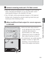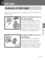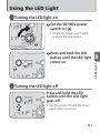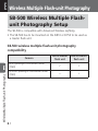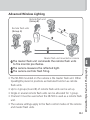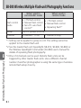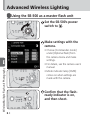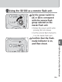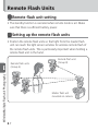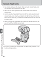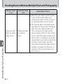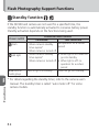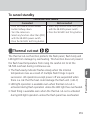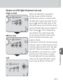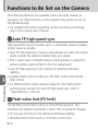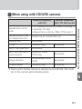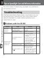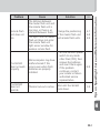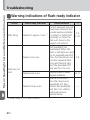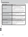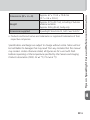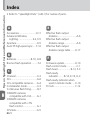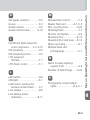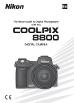
1
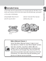
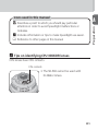
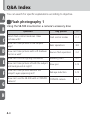
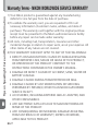
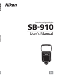
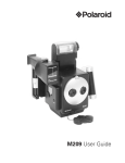
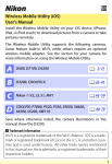
SB-500 Speedlight User's Manual (with Warranty) Nikon Manual Viewer 2 Use the Nikon Manual Viewer 2 app to view manuals anytime, anywhere on your smartphone or tablet. En About the SB-500 and This User’s Manual Preparation A Thank you for purchasing the Nikon Speedlight SB-500. To get the most out of your Speedlight, please read this user’s manual thoroughly before use. How to find what you are looking for i Table of contents (0A-10) You can search by item, such as operation method, flash control mode or function. i Q&A index (0A-8) You can search according to objective without knowing the specific name or term of an item. i Index (0H-21) You can search using the alphabetical index. i Troubleshooting (0H-1) This is handy when there is a problem with your Speedlight. For your safety Before using the Speedlight for the first time, read the safety instructions in “For Your Safety.” (0A-13–A-17) A-2 Check that all items listed below are included with the SB-500. If any items are missing, inform the store where the SB-500 was purchased or the seller immediately. ❑ User’s manual (this manual) ❑ Warranty card SPEEDLIGHT SB-500 ❑ Speedlight Stand AS-23 ❑ Soft Case SS-DC2 Speedlight Stand AS-23 SB-500 Nikon Manual Viewer 2 Install the Nikon Manual Viewer 2 app on your smartphone or tablet to view Nikon digital camera manuals, anytime, anywhere. Nikon Manual Viewer 2 can be downloaded free of charge from the App Store and Google Play. Download of the app and any product manuals requires an Internet connection, for which fees may be levied by your phone or Internet service provider. A-3 A Preparation Included items About the SB-500 and This User’s Manual Preparation A About the SB-500 The SB-500 is a light and compact Speedlight compatible with Nikon Creative Lighting System (CLS) with a guide number of 24/78.7 (ISO 100, m/ft). The SB-500 works as both a master flash unit and a remote flash unit in wireless multiple flash-unit photography. The SB-500’s LED light, which has a maximum output level of approximately 100 lx at 1 m (3.3 ft), provides illumination for photography and additional lighting for movie recording. CLS-compatible cameras Nikon digital SLR (Nikon FX/DX format) cameras (except D1 series and D100), F6, CLS-compatible COOLPIX cameras (0G-1) • The SB-500 can be used as a master flash unit only when mounted on the D810 or D750. • The SB-500’s LED light is designed for photography and movie recording. Do not use it for other purposes. About this user’s manual This manual has been compiled with the assumption that the SB-500 will be used in combination with a camera compatible with CLS and a CPU lens (0A-5). To get the most out of your Speedlight, please read this user’s manual thoroughly before use. • For use with COOLPIX cameras compatible with i-TTL flash control (P5100, P5000, E8800, E8700, E8400), see “For Use with COOLPIX Cameras.” (0G-1) • For camera functions and settings, see the camera user’s manual. A-4 Icons used in this manual Describes a point to which you should pay particular attention in order to avoid Speedlight malfunctions or mistakes. t 0 Includes information or tips to make Speedlight use easier. A Preparation v Reference to other pages in this manual t Tips on identifying CPU NIKKOR lenses CPU lenses have CPU contacts. CPU contacts • The SB-500 cannot be used with IX-Nikkor lenses. A-5 About the SB-500 and This User’s Manual Terminology Preparation A Nikon Creative Lighting System (CLS): a lighting system that enables flash photography functions listed below with improved communication between Nikon Speedlights and cameras i-TTL flash control/Advanced Wireless Lighting/Modeling flash/ FV lock/Flash (LED Light) Color Information Communication/ Auto FP high-speed sync Guide number (GN): the amount of light generated by a flash unit; GN = flash-to-subject distance (mƁorƁft) × aperture f-number (ISO 100) Effective flash output distance: flash-to-subject distance with correctly adjusted flash output Effective flash output distance range: range of effective flash output distance Flash exposure compensation: intentional flash output change to obtain the desired subject brightness i-TTL flash control: flash control mode in which the Speedlight fires monitor pre-flashes and the camera measures the reflected light and controls the Speedlight flash output Monitor pre-flashes: a series of flashes emitted for a very short time before the actual firing that enables the camera to measure the light reflected on a subject A-6 i-TTL balanced fill-flash: i-TTL flash control type in which flash A Preparation output level is adjusted to well-balanced exposure of the main subject and background Standard i-TTL flash: i-TTL flash control type in which flash output level is adjusted to the correct exposure of the main subject regardless of background brightness Manual flash control: flash control mode in which the flash output level and aperture are manually set to obtain the desired exposure Wireless multiple flash-unit photography: flash photography with multiple wireless flash units simultaneously firing Master flash unit: the flash unit that commands remote flash units in multiple flash-unit photography Remote flash unit: a flash unit that fires following commands from the master flash unit Advanced Wireless Lighting: wireless multiple flash-unit photography with CLS; multiple remote flash unit groups can be controlled with the master flash unit A-7 Q&A Index Preparation A B C D E F G You can search for specific explanations according to objective. Flash photography 1 Using the SB-500 mounted on a camera’s accessory shoe Question Key phrase 0 Which flash control mode can I take pictures with? Flash control modes C-1 How can I take pictures in the simplest way? Basic operations B-9 How can I take pictures with soft shadows cast on a wall? Bounce flash operation F-2 How can I confirm lighting conditions? Modeling flash F-7 How can I take pictures of both the subject and background at night? Slow sync F-13 How can I take pictures without the subject’s eyes appearing red? Red-eye reduction F-13 How can I use the SB-500 with a COOLPIX camera? COOLPIX camera G-1 H A-8 Question Key phrase 0 What are the features of the LED light? LED light D-1 How can I use the LED light? Using the LED light D-3 A Preparation LED light photography and movie recording Using the LED light B C Flash photography 2 Using the wireless SB-500 Question Key phrase 0 How do I take pictures using multiple flash units? Advanced Wireless Lighting E-2, E-5 How do I take pictures with the SB-500 and a COOLPIX camera compatible with wireless multiple flash-unit photography? COOLPIX cameras compatible with CLS G-1 D E F G H A-9 Table of Contents Preparation A A B C D E A-10 Preparation About the SB-500 and This User’s Manual ........................ A-2 Q&A Index ....................................................................... A-8 For Your Safety .............................................................. A-13 Check before Use .......................................................... A-18 Operation Speedlight Parts ................................................................B-1 Notes on Continuous Use .................................................B-7 Basic Operations ..............................................................B-9 Flash Control Modes i-TTL Flash Control ........................................................... C-1 Manual Flash Control ....................................................... C-3 LED Light Features of LED Light ....................................................... D-1 Using the LED Light ......................................................... D-3 Wireless Multiple Flash-unit Photography SB-500 Wireless Multiple Flash-unit Photography Setup ....E-1 SB-500 Wireless Multiple Flash-unit Photography Functions .....................................................................E-3 Advanced Wireless Lighting ..............................................E-5 Remote Flash Units ...........................................................E-7 Checking Status in Wireless Multiple Flash-unit Photography ..............................................................E-10 G Functions Bounce Flash Operation .................................................... F-2 Flash Photography Support Functions................................ F-7 • Test firing • Modeling flash • Standby function • Thermal cut-out Functions to Be Set on the Camera ................................. F-12 • Auto FP High-speed sync • Flash value lock (FV lock) • Slow sync • Red-eye reduction • Rear-curtain sync • Exposure compensation/Flash exposure compensation For Use with COOLPIX Cameras...................... G-1 A-11 A Preparation F Table of Contents A H Tips on Speedlight Care and Reference Information Preparation Troubleshooting ............................................................... H-1 Guide Number, Aperture and Flash-to-subject Distance .... H-5 Tips on Speedlight Care ................................................... H-6 Notes on Batteries............................................................ H-8 Updating Firmware ........................................................ H-10 Optional Accessories ...................................................... H-11 Specifications ................................................................. H-13 Index ............................................................................. H-21 Warranty Terms - NIKON WORLDWIDE SERVICE WARRANTY .............................................................. H-27 A-12 For Your Safety This icon marks warnings and information that should be read before using this Nikon product to prevent possible injury. WARNINGS Turn off in the event of malfunction. Should you notice smoke or an unusual smell coming from the product, remove the batteries immediately, taking care to avoid burns. Continued operation could result in injury. After removing the power source, take the product to a Nikon-authorized service representative for inspection. Do not disassemble or subject to powerful physical shocks. Touching the product’s internal parts could result in injury. Repairs should be performed only by qualified technicians. Should the product break open as the result of a fall or other accident, take it to a Nikon-authorized service representative for inspection, after disconnecting the product from the camera and/or removing the batteries. A-13 A Preparation To prevent damage to your Nikon product or injury to yourself or others, read the following safety precautions in their entirety before using this equipment. Keep these safety instructions where all those who use the product will read them. For Your Safety Preparation A Keep dry. Do not immerse in or expose to water or rain. Failure to observe this precaution could result in fire or electric shock. Do not handle with wet hands. Failure to observe this precaution could result in electric shock. Do not use in the presence of flammable gas or dust. Use of electronic equipment in the presence of flammable gas or dust could result in explosion or fire. Keep out of reach of children. Failure to observe this precaution could result in injury. Do not clean with organic solvents such as paint thinner or benzene, spray with insecticide, or store with naphtha or camphor moth balls. Failure to observe this precaution could damage or discolor the product’s plastic parts. Observe caution when handling batteries. Batteries may leak, overheat, or rupture if improperly handled. When handling batteries for use in this product, follow all instructions and warnings printed on or included with the batteries and observe the following precautions: • Do not combine old and new batteries or batteries of different makes or types. • Do not attempt to recharge non-rechargeable batteries. When recharging Ni-MH batteries, follow instructions and use compatible chargers only. A-14 A-15 A Preparation • Insert batteries in the correct orientation. • Batteries may become hot if the flash is fired multiple times in quick succession. When removing the batteries, take precaution to avoid burns. • Do not short or disassemble batteries or attempt to remove or otherwise damage the battery insulation or casing. • Do not expose to flame or excessive heat, immerse in or expose to water, or subject to physical force. • Do not transport or store with metal objects such as necklaces or hairpins. • Batteries are prone to leakage when fully discharged. To avoid damage to the product, be sure to remove the batteries when no charge remains or if the product will not be used for an extended period. • Discontinue use immediately should you notice any change in the batteries, such as discoloration or deformation. • If liquid from damaged batteries comes in contact with clothing, eyes or skin, rinse immediately with plenty of water. • Dispose of used batteries in accord with local regulations. Prior to disposal, insulate the terminals with tape. Fire, overheating or rupture may result should metal objects come into contact with the terminals. For Your Safety Preparation A Observe caution when using the flash • Using a flash in close contact with the skin or other objects could cause burns. • Using the flash close to subject’s eyes could cause temporary visual impairment. Stay at least 1 m (3.3 ft) from the subject when using the flash. • Do not aim the flash at the operator of a motor vehicle. Failure to observe this precaution could result in accidents. Observe caution when using the LED light • Using the LED light in close contact with the skin or other objects could cause burns. • Looking directly at the LED light or shining it directly in subject’s eyes (particularly those of infant) could cause temporary visual impairment. Keep the light at least 1 m (3.3 ft) from the subject. • Do not aim the LED light at the operator of a motor vehicle. Failure to observe this precaution could result in accidents. A-16 Notice for Customers in Canada CAN ICES-3 B / NMB-3 B Notice for customers in Europe This symbol indicates that electrical and electronic equipment is to be collected separately. The following apply only to users in European countries: • This product is designated for separate collection at an appropriate collection point. Do not dispose of as household waste. • Separate collection and recycling helps conserve natural resources and prevent negative consequences for human health and the environment that might result from incorrect disposal. • For more information, contact the retailer or the local authorities in charge of waste management. A-17 Preparation A Check before Use Preparation A Tips on using the Speedlight Take trial shots Take trial shots before photographing important occasions such as weddings or graduations. Have Nikon spot-check your Speedlight regularly Nikon recommends that you have your Speedlight serviced by an authorized dealer or service center at least once every 2 years. Use your Speedlight with Nikon equipment The Nikon Speedlight SB-500’s performance has been optimized for use with Nikon brand cameras/accessories including lenses. Cameras/ accessories made by other manufacturers may not meet Nikon’s criteria for specifications, and incompatible cameras/accessories could damage the SB-500’s components. Nikon cannot guarantee the SB-500’s performance when used with non-Nikon products. A collection of example photos “A collection of example photos” provides an overview of the SB-500’s flash photography capabilities with example images. To download the PDF file, access the link below and choose “Speedlights” from the “Digital SLR Cameras” category, then go to the “SB-500.” http://nikonimglib.com/manual/ A-18 As part of Nikon’s “life-long learning” commitment to ongoing product support and education, continually updated information is available online at the following websites: • For users in the United States: http://www.nikonusa.com/ • For users in Europe and Africa: http://www.europe-nikon.com/support/ • For users in Asia, Oceania and the Middle East: http://www.nikon-asia.com/ Visit these sites to keep up to date with the latest product information, tips, answers to frequently-asked questions (FAQs) and general advice on digital imaging and photography. Additional information may be available from the Nikon representative in your area. See the URL below for contact information: http://imaging.nikon.com/ A-19 A Preparation Life-long learning B Operation Speedlight Parts B Operation 8 2 1 00 -5 HT SB IG DL E PE S 5 3 6 4 7 B-1 Flash head LED light (0D-1) Light sensor window for wireless remote flash (0E-7) Battery chamber cover Locking pin Accessory shoe contacts Mounting foot Flash panel B Operation 1 2 3 4 5 6 7 8 B-2 Speedlight Parts 9 Operation B 11 10 12 B-3 9 10 11 12 Operation B Flash head tilting angle scale (0F-3) Flash head rotating angle scale (0F-3) Flash-ready indicator (0B-14, E-10) Mounting foot lock lever (0B-12) B-4 Speedlight Parts Operation B 13 16 14 15 17 18 B-5 17 Power switch • Rotate to turn power on and off. • Set the index to choose the function to be used. : Flash (0B-14, C-3, E-5) : LED light (0D-3) A: Remote mode group A (0E-6) B: Remote mode group B (0E-6) 18 Lock release (0D-3, E-6) Rotate the power switch while pressing this button to switch between [ ], [ ] and [A]. B-6 Operation B 13 LED button (0D-3) : Press and hold down to turn the LED light on and off. : Press briefly to change LED light output level. 14 LED light output level indicator lamps (0D-4) Indicate LED light output level 15 Mode indicator lamps Indicate flash control mode TTL: i-TTL flash control M: Manual flash control CMD: Commander mode 16 Test firing button (0F-7) Controls test firing Notes on Continuous Use Notes on continuous flash firing Operation B • To prevent the SB-500 from overheating, allow it to cool down for at least 10 minutes after the number of firings indicated below. Flash control mode Firing limit i-TTL flash control Manual flash control (output volume: M 1/1, M 1/2) Up to 15 times Manual flash control (output volume: M 1/4–M 1/128) Up to 40 times • When continuous flash firing is repeated in quick succession, the internal safety function extends the recycling time. • If flash firing continues, it may be temporarily suspended. The internal safety function is deactivated and flash firing becomes available after cooling down for several minutes. (0F-9) • The condition in which the internal safety function is activated differs depending on the SB-500 output level and the ambient temperature. • The condition in which the internal safety function is deactivated differs depending on the ambient temperature. B-7 Notes on LED light operation duration B-8 B Operation • The internal safety function automatically lowers the LED light output level by 1 level when the LED light is used for an extended period of time. (0F-11) • If the LED light is used for a longer period, the internal safety function turns the LED light off. The internal safety function is deactivated and the LED light becomes available after cooling down for several minutes. (0F-9) • The condition in which the internal safety function is activated differs depending on the LED light output level and the ambient temperature. • The condition in which the internal safety function is deactivated differs depending on the ambient temperature. Basic Operations This section covers basic procedures in i-TTL flash control in combination with a CLS-compatible camera. Slide the battery chamber cover open. Operation B STEP 1 Inserting the batteries Insert the batteries following the [+] and [−] marks. Close the battery chamber cover. B-9 Suitable batteries 1.5 V LR6 (AA-size) alkaline battery 1.2 V HR6 (AA-size) rechargeable Ni-MH battery • For minimum recycling time and number of flashes for each battery type, refer to “Specifications.” (0H-20) • Alkaline battery performance may vary greatly depending on the manufacturer. • 1.5 V R6 (AA-size) carbon-zinc batteries are not recommended. v Additional precautions regarding batteries • Read and follow battery cautions on “For Your Safety.” (0A-13– A-17) • Be sure to read and follow the warnings for the battery on the section, “Notes on Batteries” (0H-8), before using the battery. B-10 B Operation Replace both batteries at the same time using fresh batteries or fully-charged rechargeable batteries of the same brand from any of the following types. Do not mix old and new batteries or batteries of different types or makes. Basic Operations Replacing/recharging batteries Operation B Refer to the following table to determine when to replace batteries with fresh ones or recharge batteries according to how long the flashready indicator takes to light up after turning the SB-500 on or flash firing. 1.5 V LR6 (AA-size) alkaline battery 20 sec. or more 1.2 V HR6 (AA-size) rechargeable Ni-MH battery 15 sec. or more Low battery power indication When battery power is low, the flash-ready indicator flashes repeatedly twice per sec. for approximately 40 sec. Replace or recharge batteries. B-11 STEP 2 Attaching the SB-500 to the camera v Lock the Speedlight in place Turn the mounting foot lock lever clockwise until it clicks into place pointing to “LOCK.” v Cameras with auto pop-up flash units Turn the SB-500 on when it is mounted on a camera with a built-in, auto pop-up flash unit. When the SB-500 is turned off, the camera’s built-in flash may pop-up automatically and strike the SB-500. It is recommended to detach the SB-500 from the camera when not in use. B-12 B Operation Make sure the SB-500 and the camera body are turned off. Make sure the mounting foot lock lever is on the left. Slide the SB-500’s mounting foot into the camera’s accessory shoe. Turn the mounting foot lock lever to “LOCK.” Basic Operations Detaching the SB-500 from the camera Make sure the SB-500 and the camera body are turned off, turn the mounting foot lock lever 90° to the left, and then slide the SB-500’s mounting foot from the camera’s accessory shoe. Operation B • If the SB-500’s mounting foot cannot be removed from the camera’s accessory shoe, turn the mounting foot lock lever 90° to the left again, and slide the SB-500 slowly out. • Do not forcibly remove the SB-500. STEP 3 Adjusting the flash head Adjust the flash head to the forward-facing position. B-13 STEP 4 Turning the power on Turn the camera on. Set the SB-500’s power switch to [ ]. • Mode indicator lamp [TTL] comes on. STEP 5 Taking a picture Make sure that the flashready indicator on the SB-500 or in the camera’s viewfinder is on, and then shoot. B-14 Operation B C Flash Control Modes The SB-500 has 2 flash control modes—manual flash control and i-TTL flash control. • Flash control modes cannot be selected on the SB-500. The setting of the camera on which the SB-500 is mounted automatically applies. Flash Control Modes C i-TTL Flash Control Information obtained by monitor pre-flashes and exposure control information is integrated by the camera to automatically adjust flash output levels. • To take pictures using the SB-500 set in i-TTL flash control, see “Basic Operations.” (0B-9) • Either the i-TTL balanced fill-flash or the standard i-TTL flash option is available depending on the camera settings. i-TTL flash control options cannot be selected on the SB-500. i-TTL balanced fill-flash The flash output level is automatically adjusted for well-balanced exposure of the main subject and background. Standard i-TTL flash The main subject is correctly exposed regardless of background brightness. This is useful when you want to highlight the main subject. C-1 t Camera’s metering mode and i-TTL flash control v When insufficient flash output for correct exposure is indicated • When the flash-ready indicators on the SB-500 and in the camera’s viewfinder flash slowly for approximately 3 sec. after firing, underexposure due to insufficient flash output may have occurred. • To compensate, use a wider aperture (smaller f-number) or higher ISO sensitivity, or move the flash unit closer to the subject and reshoot. C-2 C Flash Control Modes • When the camera’s metering mode is changed to spot metering while i-TTL balanced fill-flash is in use, the i-TTL flash control automatically changes to the standard i-TTL flash. • The i-TTL flash control automatically changes to i-TTL balanced fill-flash, after changing the camera’s metering mode from spot metering to other metering modes. Manual Flash Control When the SB-500 is mounted on a camera, manual setting of flash output level can be enabled by selecting [Manual] under [Optional flash] from the camera menu. • Monitor pre-flash and the indication of insufficient flash output for correct exposure are not available in manual flash control. • Manual flash control is not available with D3 series, D2 series, D200, D80, D70 series, D50 and F6 cameras. C Flash Control Modes Taking a picture in manual flash control Set the SB-500’s power switch to [ ]. Set the flash output level with the camera. • For details, see the camera user’s manual. • Mode indicator lamp [M] comes on when the setting is made with the camera. Confirm that the flashready indicator is on, and then shoot. C-3 D LED Light Features of LED Light The SB-500 is equipped with an LED light that has various features, as detailed below. Continuous light that enhances your photography Soft light suitable for close-up photography Control of glare on the subject and shadows is a decisive factor in closeup photography, such as tabletop photography. The LED light’s soft light beam with natural-looking color tone is suitable for close-up photography. D-1 D LED Light In contrast to a flash light, the LED light is a continuous light source. You can check the lighting effects in real time with live view and so achieve your desired composition easily. The LED light is also suitable for additional illumination for recording movies. Features of LED Light Off-camera lighting that inspires creativity The LED light’s soft light beam blends smoothly with natural light. You can illuminate your subject freely from any angle, height and distance by using the SB-500 off-camera. Flexibility that makes use of multiple light source easier D LED Light Multiple light sources expand your creative expression. Photography using multiple lights usually requires a certain amount of expertise to control lighting effects, but the SB-500 makes it easy. Simply use multiple SB-500s to achieve your intended results by checking lighting effects in real time with live view. • Use the provided Speedlight Stand AS-23 for stable positioning of the SB-500. Attach and detach the SB-500 to and from the AS-23 in the same way it is attached to/detached from the camera’s accessory shoe. • When carrying the Speedlight Stand with the SB-500 attached, be sure to hold the SB-500 in your hand. D-2 Using the LED Light Turning the LED light on Set the SB-500’s power switch to [ ]. • Rotate the power switch while pressing the lock release. Turning the LED light off Press and hold the LED button until the LED light goes off. • Turn the power off with the power switch when not in use. D-3 D LED Light Press and hold the LED button until the LED light comes on. Using the LED Light Changing the LED light output level Briefly press the LED button to change the LED light output level. • The LED light output level changes as shown in the diagram below. The output level is indicated by the LED light output level indicator lamps. • The LED light output level also can be changed when the LED light is off. • Holding the LED button switches the LED light on and off, and does not change the LED light output level. LED Light D Low power D-4 Mid power High power v Operation of the LED light when attached to the camera • LED light operation is manual only. The LED light does not synchronize with the camera shutter. • The LED light turns off when the SB-500 is in standby and does not turn on when the SB-500 comes on again. v White balance settings Set the camera’s white balance as shown in the table below for photography with the SB-500’s LED light. • See the camera user’s manual for white balance settings. LED Light D White balance settings by camera type Camera White balance setting Nikon digital SLR cameras with LED Light Color Information Communication D810, D750 Auto, Flash Nikon digital SLR cameras without LED Light Color Information Communication Auto*, Direct sunlight Nikon digital SLR cameras D1, D50 Auto, Direct sunlight COOLPIX cameras (0G-1) Auto, Direct sunlight * Adjust the white balance setting depending on results. D-5 E Wireless Multiple Flash-unit Photography SB-500 Wireless Multiple Flashunit Photography Setup The SB-500 is compatible with Advanced Wireless Lighting. • The SB-500 has to be mounted on the D810 or D750 to be used as a master flash unit. SB-500 wireless multiple flash-unit photography compatibility Use as master flash unit Use as remote flash unit With Speedlight commander mode (CMD) Without Speedlight commander mode (CMD) — Camera Wireless Multiple Flash-unit Photography E E-1 Advanced Wireless Lighting Remote flash unit (Group B) Remote flash units (Group A) Master flash unit mounted on camera The master flash unit commands the remote flash units to fire monitor pre-flashes. The camera measures the reflected light. The camera controls flash firing. • The SB-500 mounted on the camera is the master flash unit. Other Speedlights placed in positions as illustrated function as remote flash units. • Up to 2 groups (A and B) of remote flash units can be set up. • Single or several remote flash units can be allocated for 1 group. • Channel 3 must be used when the SB-500 is used as a remote flash unit. • The camera settings apply to the flash control modes of the remote and master flash units. E-2 Wireless Multiple Flash-unit Photography E SB-500 Wireless Multiple Flash-unit Photography Functions When used in commander mode Flash control mode • i-TTL flash control • Manual flash control • Non-TTL auto flash control*1 Wireless Multiple Flash-unit Photography E Group Up to 2 groups (A and B) Channel 4 channels*3 (1–4) When used in remote mode • i-TTL flash control • Manual flash control • Repeating flash*2 1 channel (3 only) *1 Setting can be applied to group A or B. The setting cannot be applied to the master flash unit. *2 See the master flash unit Speedlight (SB-910, SB-900, SB-800) or the Wireless Speedlight Commander (SU-800) user’s manual for details of repeating flash photography. *3 One of 4 channels can be used. Remote flash units can be triggered by other master flash units. Use a different channel number if another photographer is using the same type of wireless remote flash setup close by. E-3 v Notes on canceling the flash of the master flash unit When the master flash unit flash function is canceled and only the remote flash units fire, the master flash unit emits a number of weak light signals to trigger the remote flash units. This operation will normally not affect the correct exposure of the subject, although the exposure might be affected if the subject is close and a high ISO sensitivity has been set. To limit this effect, tilt up the master flash unit’s flash head. Wireless Multiple Flash-unit Photography E E-4 Advanced Wireless Lighting Using the SB-500 as a master flash unit Set the SB-500’s power switch to [ ]. Make settings with the camera. • Choose [Commander mode] under [Optional flash] from the camera menu and make settings. • For details, see the camera user’s manual. • Mode indicator lamp [CMD] comes on when settings are made with the camera. Wireless Multiple Flash-unit Photography E Confirm that the flashready indicator is on, and then shoot. E-5 Using the SB-500 as a remote flash unit Set the power switch to [A] or [B] to correspond with the remote flash group selected on the master flash unit. • Rotate the power switch while pressing the lock release. • Set the remote flash channel to 3 on the master flash unit. Confirm that the flashready indicator is on, and then shoot. Wireless Multiple Flash-unit Photography E E-6 Remote Flash Units Remote flash unit setting • The standby function is canceled when remote mode is set. Make sure that there is sufficient battery power. Setting up the remote flash units • Position the remote flash units so that light from the master flash unit can reach the light sensor window for wireless remote flash of the remote flash units. This is particularly important when holding a remote flash unit in the hand. Wireless Multiple Flash-unit Photography E Remote flash units (Group A) Remote flash unit (Group B) Master flash unit mounted on camera E-7 • As a basic guide, the effective distance between the master and remote flash units is up to approximately 10 m (32 ft) in the forward-facing position, and approximately 7 m (22 ft) at both sides. These ranges vary slightly depending on ambient light. • There is no limit to the number of remote flash units that can be used together. However, when using many remote flash units, light may be unintentionally picked up by the light sensor of the master flash unit and interfere with correct functioning. Therefore, the number of remote flash units used for wireless multiple flash-unit photography should be limited to around 3 for 1 group. • Place all remote flash units in the same group close together and facing the same direction. Group B Less than approx. 7 m (22 ft) E Wireless Multiple Flash-unit Photography Group A Less than approx. 10 m (32 ft) Within 60˚ Master flash unit E-8 Remote Flash Units • An obstacle between the master flash unit and remote flash units can interfere with transmission of data. • Take care not to let light from the remote flash units enter the camera lens. • Use the provided Speedlight Stand AS-23 for stable positioning of remote flash units. Attach and detach the SB-500 to and from the AS-23 in the same way it is attached to/detached from the camera’s accessory shoe. • When carrying the Speedlight Stand with the SB-500 attached, be sure to hold the SB-500 in your hand. Wireless Multiple Flash-unit Photography E • Be sure to confirm the remote flash unit flash-ready indicator is on before photographing. E-9 Checking Status in Wireless Multiple Flash-unit Photography The flash-ready indicator on the SB-500 can be used to check the status during and after taking a picture in wireless multiple flash-unit photography. Checking flash operation using the flash-ready indicator Remote flash unit Lights up Goes out and lights up when ready to fire Lights up Goes out and lights up when ready to fire Flashes slowly for approx. 3 sec. Flashes slowly for approx. 3 sec. Speedlight status Ready to fire Fired properly Insufficient flash output for correct exposure Underexposure due to insufficient flash output may have occurred. To compensate, use a wider aperture (smaller f-number) or higher ISO sensitivity, or move the flash unit closer to the subject and reshoot. E-10 E Wireless Multiple Flash-unit Photography Master flash unit Checking Status in Wireless Multiple Flash-unit Photography Master flash unit Remote flash unit Speedlight status • Non-TTL auto flash control mode Goes out and lights up when ready to fire Wireless Multiple Flash-unit Photography E E-11 Flashes quickly for approx. 6 sec. is set on the master flash unit. Change the flash control mode to an operable flash control mode. • The remote flash unit light sensor has failed to receive the command light from the master flash unit. This is because the light sensor cannot detect when to stop firing in sync with the master flash unit, either due to a reflection from the remote flash unit itself or light from another remote flash unit that may have entered the light sensor window. Change the direction or position of the remote flash unit and reshoot. F Functions This section explains the SB-500 functions that support flash photography and functions to be set on the camera. • For detailed information regarding camera functions and settings, refer to the camera user’s manual. Bounce flash operation (0F-2) Test firing Flash photography Modeling flash support functions Standby function (0F-7) Thermal cut-out Auto FP high-speed sync FV lock Functions to be Slow sync set on the camera Red-eye reduction (0F-12) Rear-curtain sync Exposure compensation/Flash exposure compensation Functions F F-1 Bounce Flash Operation Bounce flash is a photographic technique using light that is bounced off a ceiling or wall using a tilted or rotated flash head. This provides the effects listed below compared to those with direct light from a flash unit: • Overexposure to a subject that is closer than other subjects can be reduced. • Background shadows can be softened. • Glare on faces, hair and clothes can be reduced. Functions F F-2 Setting the flash head Tilt or rotate the flash head. • The flash head tilts up from 0° to 90° and rotates horizontally 180° to the left and right. • Set the flash head at a click stop at the angles shown. 30˚ 0˚ 30˚ ˚ 120 120 ˚ F Functions 180˚ 150 ˚ 0° 90˚ 90˚ 75˚ 75˚ 60˚ 60˚ 60˚ ˚ 150 90˚ 75˚ F-3 Bounce Flash Operation Selecting flash head tilting/rotating angles and a reflecting surface Functions F • Good results are most easily achieved when the flash head is tilted up to use the ceiling as a reflecting surface. • Rotate the flash head horizontally to get the same effect when the camera is held in the vertical position. • Illumination can be softened further when the light is bounced off a ceiling or wall behind the camera, as opposed to in front of the camera. • Select white and highly reflective surfaces to bounce the light off. Otherwise, image colors will be influenced by the color of the reflecting surface. • Avoid illuminating the subject directly to achieve successful bounce flash photography. • The recommended distance between the flash head and the reflecting surface is approximately 1 m to 2 m (3.3 ft to 6.5 ft), but this number may vary depending on photographic conditions. • If the reflecting surface is not close enough, a piece of A4-size white paper can be used instead. Check that the subject is exposed to the bounced light before taking a picture. F-4 Behind the camera White ceiling 1-2 m 90º Lightproof white paper Functions F F-5 Bounce Flash Operation Taking a picture with bounce flash Set the SB-500’s power switch to [ ]. Adjust the flash head and shoot. t Exposure in bounce flash operation Functions F In bounce flash, there is some light loss compared with normal flash photography (with flash head adjusted to the forward-facing position). Therefore, a 2- or 3-step wider aperture (smaller f-number) or a 2- or 3-step higher ISO sensitivity should be used when taking pictures with manual exposure. Adjust according to results. F-6 Flash Photography Support Functions The SB-500 features flash photography support functions. indicates functions used with the flash light. indicates • functions used with the LED light. Test firing Pressing the test firing button determines whether the SB-500 fires properly. • The flash output level during test firing varies depending on settings and flash control modes. Modeling flash ■ Advanced Wireless Lighting • When the camera’s depth-of-field preview button is pressed, the master flash unit (with the flash function activated) and all other remote flash units fire as modeling flashes at the set flash output level at the selected mode. F-7 F Functions The flash fires repeatedly at a reduced flash output level. This is useful for checking the illumination and shadows cast on a subject before actually taking the picture. • When the depth-of-field preview button on a camera compatible with modeling flash is pressed, the modeling flash fires. For details, see the camera user’s manual. • The modeling flash fires for up to approximately 1 sec. Flash Photography Support Functions Standby function If the SB-500 and camera are not used for a specified time, the standby function is automatically activated to conserve battery power. Standby activation depends on the functions being used. Power switch Flash LED light A / B Remote mode group Functions F Connection with camera Connected Not connected No operation for a certain • When camera’s standby period timer expires* • When camera is turned off • When light is on: does not • When camera’s standby go into standby timer expires* • When camera is turned off • When light is off: no operation for a certain period Does not go into standby Does not go into standby * For details regarding the standby timer, refer to the camera user’s manual. The standby timer is called “auto meter off” for some camera models. F-8 To cancel standby • • • • Connection with camera Connected Not connected • Select any function other than [OFF] Press the camera shutter-release with the SB-500’s power switch. button halfway down. • Press the SB-500’s test firing button. Turn the camera on. Select any function other than [OFF] with the SB-500’s power switch. Press the SB-500’s test firing button. Thermal cut-out F-9 F Functions The thermal cut-out function protects the flash panel, flash body and LED light from damage by overheating. This function does not prevent the flash head temperature from rising. Be careful not to let the SB-500 overheat during continuous use. • The flash-ready indicator flashes slowly when the internal temperature rises as a result of multiple flash firings in quick succession. All operations except power off are suspended when there is a risk that the heat could damage the flash unit. (0H-3) • LED light operation is available even when thermal cut-out is activated during flash operation unless the LED light has overheated. • Flash firing is available even when the thermal cut-out is activated during LED light operation unless the flash panel has overheated. Flash Photography Support Functions Warning of flash-ready indicator Flashes once per sec. • Wait until the SB-500 cools down. • Operation can be resumed once the warning goes off. Functions F F-10 Notes on LED light thermal cut-out Mid to low Off When the LED light is operating at high power and the internal temperature reaches a certain point, the LED light output level falls to mid power [ ] and the right lamp of the LED light output level indicator lamps, which indicates high power, begins to flash slowly [ ]. If the temperature rises further, the output level falls to low power and the center lamp, which indicates mid power, also begins to flash. If operation continues, the flash-ready indicator starts to flash slowly and the internal safety function turns the LED light off. When this happens, allow the SB-500 to cool down for a while and then turn the power on again. The LED light will not automatically return to the same LED light output level it was at before turning off. F-11 F Functions High to mid Functions to Be Set on the Camera The following functions are available when used with cameras so equipped. Set these functions on the camera. They cannot be set on the SB-500 directly. • For detailed information regarding camera functions and settings, refer to the camera user’s manual. Auto FP high-speed sync Functions F High-speed flash synchronization up to a compatible camera’s highest shutter speed is possible. • Auto FP high-speed sync mode is automatically set when the shutter speed exceeds the camera’s highest flash sync speed. • This is useful even in daylight when a wider aperture is required to achieve shallow depth of field to blur the background. • Auto FP high-speed sync also operates in Advanced Wireless Lighting. • Available flash control modes are i-TTL flash control and manual flash control. • For effective flash output distance range for i-TTL flash control and the guide numbers for auto FP high-speed sync, refer to “Specifications.” (0H-19) Flash value lock (FV lock) The SB-500 sets the flash output to locked flash exposure. This maintains the subject’s illumination, even if the composition changes. • FV lock also functions in the Advanced Wireless Lighting. • Operable flash control mode is i-TTL flash control only. F-12 Slow sync The camera slows the shutter speed to capture both the subject and background illumination. This is suitable for capturing the subject and background illumination during the evening and night. • Use of a tripod is recommended. Red-eye reduction The SB-500 fires 3 flashes at low output just before the picture is taken to reduce the red-eye effect caused by the flash light. Rear-curtain sync Rear-curtain sync flash creates the effect of a smooth stream of light behind the subject. • A slow shutter speed is usually used. Use of a tripod is recommended. Exposure and flash exposure can be compensated using settings on the camera. F-13 F Functions Exposure compensation/Flash exposure compensation For Use with COOLPIX Cameras G For Use with COOLPIX Cameras Using the SB-500 with COOLPIX cameras is also possible, although some functions may not be available. COOLPIX cameras compatible with CLS (A, P7800, P7700, P7100*1, P7000*1, P6000) COOLPIX cameras compatible with i-TTL flash control (P5100, P5000, E8800, E8700, E8400) • See the camera user’s manual as well. *1 Only the flash light can be used when the SB-500 is mounted on COOLPIX P7100 or P7000. Detach the SB-500 from the camera when using the LED light. G G-1 When using with COOLPIX cameras Operable flash control mode Operable wireless mode for multiple flash units Modeling flash Cameras compatible with i-TTL flash control • i-TTL balanced fill-flash (A, P7800, P7700 only*2) • Standard i-TTL flash • Manual flash control (A, P7800, P7700 only*2) Possible only as a remote flash unit Not possible FV lock Possible (A only) Auto FP high-speed sync Not possible Not possible Flash Color Information Communication Possible (A, P7800, P7700 only) Not possible Red-eye reduction Possible (except P7800, P7700) Not possible Firmware update Possible (A only) Not possible *2 Flash control modes cannot be selected on the SB-500. The mode set on the camera automatically applies. For Use with COOLPIX Cameras Cameras compatible with CLS G G-2 Tips on Speedlight Care and Reference Information H Tips on Speedlight Care and Reference Information This section explains troubleshooting, Speedlight care, specifications and optional accessories. Troubleshooting If the flash-ready indicator flashes slowly, or any trouble occurs, use the following chart to determine the cause of the problem before taking the Speedlight to a retailer or Nikon-authorized service representative for repair. Problems with the SB-500 Problem The power cannot be turned on. The flash-ready indicator does not light up. Cause 0 Insert the batteries correctly. B-9 Battery power is weak. Replace the batteries. B-11 The standby function is activated. • Press the camera shutter-release button halfway. • Set the SB-500’s power switch to any mode other than [OFF]. • Press the SB-500’s test firing button. Battery power is weak. Replace the batteries. The power switch is set to [ ]. • Normal operation • The flash-ready indicator does not flash when the LED light is in operation, except for warning indications. H H-1 Solution The batteries are not correctly installed. F-8 B-11 — Remote flash unit does not fire. Cause Solution The distance between the master flash unit and the remote flash unit is too long, or there is an obstacle between them. Change the positioning of the master flash unit The light from the master and remote flash units. flash unit does not enter the remote flash unit light sensor window for wireless remote flash. The SB-500 does not work properly. • Set the SB-500’s power switch to any mode other than [OFF], then Microcomputer may have remove the batteries malfunctioned if this and insert them again. occurs even when fresh • If the problem batteries are properly continues, contact installed. your retailer or Nikonauthorized service representative. The SB-500 does not operate. Thermal cut-out is active. Wait until the SB-500 cools down. 0 E-7 E-8 E-9 B-9 F-9 Tips on Speedlight Care and Reference Information Problem H H-2 Tips on Speedlight Care and Reference Information Troubleshooting H Warning indications of flash-ready indicator Status After firing Flash has not fired Flash-ready indicator Cause/solution 0 Flashes for approx. 3 sec.*1 Correct exposure may not have been achieved. Use a wider aperture (smaller f-number) or higher ISO sensitivity, or move the flash unit closer to the subject and reshoot. C-2, E-10 Flashes once a sec. The Speedlight has overheated. When the flash or LED light are used for an extended period of time, the thermal cut-out function suspends flash firing and the LED light. Turn the Speedlight off and wait for it to cool. F-9 Flashes twice a sec. Battery power is weak. Replace batteries. B-11 Flashes 8 times a sec. Internal circuit error. Turn the camera and Speedlight off, then remove the Speedlight and take it to a Nikonauthorized service representative. — *1 When used in i-TTL flash control H-3 Flash-ready indicator Cause/solution The camera does not Flashes 4 times over 0.5 sec. support CLS. Flash cannot at intervals of 0.5 sec. be used. Use a CLScompatible camera. Flash has not fired 0 — • Non-TTL auto flash control mode is set on the master flash unit. Change the flash control mode to an operable flash control mode. • The remote flash unit light sensor has failed to receive the command light from the master flash unit. Flashes 4 times over 0.5 sec. This is because the light at intervals of 0.5 sec. for sensor cannot detect E-11 2 approx. 6 sec.* when to stop firing in sync with the master flash unit, either due to a reflection from the remote flash unit itself or light from another remote flash unit that may have entered the light sensor window. Change the direction or position of the remote flash unit and reshoot. *2 When used in remote mode H-4 Tips on Speedlight Care and Reference Information Status H Tips on Speedlight Care and Reference Information Guide Number, Aperture and Flash-to-subject Distance H The guide number (GN) indicates the amount of light generated by a flash unit. As the number increases, the flash output becomes greater and the light extends further. There is a relation represented by an equation, guide number (ISO 100, m/ft) = flash-to-subject distance (m or ft) × aperture f-number. The SB-500’s guide number is 24/78.7 (ISO 100, m/ft, angle of illumination: covers angle of view of 24mm lens, FX format, temperature: 23 ˚C/73.4 ˚F). When ISO sensitivity is 100 and aperture f-number is f/8, the illumination of the SB-500 reaches 3 m (9.8 ft), which is determined by the equation, flash-to-subject distance (3 m or 9.8 ft) = guide number (24/78.7) / aperture f-number (f/8). • For ISO sensitivities other than 100, multiply the guide number by the factors (ISO sensitivity factors) shown in the table below. ISO 25 50 100 200 400 800 Factor 0.5 0.71 1 1.4 2 2.8 1600 3200 6400 4 5.6 8 • See “Specifications” for the guide number table. (0H-19) t Determining aperture and flash-to-subject distance for correct exposure Aperture f-number = guide number (GN for ISO 100; m or ft) × ISO sensitivity factor / flash-to-subject distance (m or ft) Flash-to-subject distance (m or ft) = guide number (GN for ISO 100; m or ft) × ISO sensitivity factor / aperture f-number H-5 Never use thinner, benzene or other organic solvents when cleaning the Speedlight, as this may damage the WARNING Speedlight or cause it to catch fire. Using these agents may also impair your health. " Cleaning • Dirt on the flash panel can cause it to break when the flash is fired. Clean the flash panel regularly. • Use a blower to remove dust and lint, then wipe gently with a soft, dry cloth. After using the SB-500 at the beach or seaside, wipe off sand or salt with a cloth lightly dampened in distilled water and then dry the product thoroughly by wiping it gently with a dry cloth. • The SB-500 contains a large amount of precision electronics. Do not subject it to shock or vibration. Tips on Speedlight Care and Reference Information Tips on Speedlight Care H H-6 Tips on Speedlight Care and Reference Information Tips on Speedlight Care H Storage To prevent mold or mildew, store the SB-500 in a dry, well-ventilated area. If it is to be placed in storage for 2 weeks or more, remove the batteries to prevent damage caused by the batteries leaking. Take the device from storage about once a month and fire it 2 or 3 times to keep the condenser inside the unit from deteriorating. Do not store the device with naphtha or camphor moth balls, or in locations that: • are in the vicinity of equipment that produces strong electromagnetic fields, or • are exposed to extremely high temperatures that could cause product malfunction, such as next to a heater or in an enclosed vehicle on a hot day Use • Sudden changes in temperature, such as those that occur when entering or leaving a heated building on a cold day, can cause condensation inside the device. To prevent condensation, place the device in a plastic bag or other sealed container before exposing it to sudden changes in temperature. • Do not use the device in the vicinity of equipment that produces strong electromagnetic fields, such as transmission towers or highvoltage power lines. Failure to observe this precaution could cause product malfunction. H-7 • The large amounts of current used by the Speedlight may result in rechargeable batteries becoming unusable before reaching the manufacturer’s stated recharge/discharge limit. • When replacing the batteries, turn the product off and insert the replacement batteries in the correct orientation. • Dirt on the battery terminals can interrupt the flow of current. Clean dirt from the terminals before inserting the batteries. • After being fired multiple times in quick succession or using the LED light for an extended period of time, the Speedlight may stop operating to allow the batteries to cool depending on battery specifications. Normal operation can be resumed once the batteries have cooled sufficiently. • Batteries tend to lose capacity at low temperatures, recover lost voltage when allowed to rest, and slowly discharge when not in use. Be sure to check the battery level before use and replace the batteries before they are fully discharged. • Do not store batteries in locations subject to high temperatures or high humidity. Tips on Speedlight Care and Reference Information Notes on Batteries H H-8 Tips on Speedlight Care and Reference Information Notes on Batteries • For information on handling and recharging rechargeable batteries, see the documentation provided by the manufacturers of the batteries and the battery charger. • Do not attempt to recharge non-rechargeable batteries. Failure to observe this precaution could cause the batteries to rupture. Ni-MH H H-9 Recycling Used batteries are a valuable resource; rechargeable to protect the environment, recycle used batteries in accord with local regulations. batteries The latest Nikon firmware can be downloaded from the Nikon website. Firmware is updated through a Nikon digital SLR camera compatible with SB-500 firmware updates and Nikon COOLPIX A. • For users in the U.S.A.: http://www.nikonusa.com/ • For users in Europe and Africa: http://www.europe-nikon.com/support/ • For users in Asia, Oceania and the Middle East: http://www.nikon-asia.com/ • Additional information may be available from the Nikonauthorized service representative in your area. See the URL below for contact information: http://imaging.nikon.com/ • SB-500 firmware can be updated through a D3 camera with firmware A and firmware B version 2.00 or later. • SB-500 firmware can be updated through a D300 camera with firmware A and firmware B version 1.10 or later. • If your camera is not compatible with firmware updates, please contact a Nikon-authorized service representative in your area. Tips on Speedlight Care and Reference Information Updating Firmware H CLS-compatible Nikon digital SLR cameras without firmware updates D2 series, D200, D80, D70 series, D60, D50, D40 series H-10 Tips on Speedlight Care and Reference Information Optional Accessories ■ Speedlight Stand AS-23 2 1 Same as that provided with this SB-500. AS-23 parts 1 Speedlight mounting shoe 2 Tripod socket Attaching/detaching a flash unit to/from the Speedlight Stand Attach/detach your Nikon Speedlight to/ from the AS-23 in the same way as when attaching/detaching your flash unit to/from the camera’s accessory shoe. Note • When carrying the Speedlight Stand with the SB-500 attached, be sure to hold the SB-500 in your hand. Specifications Dimensions (W × H × D): approx. 57.2 × 10.4 × 72.8 mm (2.3 × 0.5 × 2.9 in.) Weight: approx. 13 g (0.5 oz) Specifications and design are subject to change without notice. H H-11 AS-21 Tips on Speedlight Care and Reference Information ■ Speedlight Stand AS-21/AS-22 AS-22 ■ TTL Remote Cord SC-28 (approx. 1.5 m/4.9 ft) The SC-28 enables i-TTL flash control when the SB-500 is used off-camera. The SC-28 is equipped with a tripod socket. ■ TTL Remote Cord SC-29 (approx. 1.5 m/4.9 ft) The SC-29 enables i-TTL flash control when the SB-500 is used off-camera. The SC-29 features an AF-assist illumination function. The SB-500 does not support the AF-assist illuminator function. H H-12 Tips on Speedlight Care and Reference Information Specifications Electronic construction Flash H H-13 Automatic Insulated Gate Bipolar Transistor (IGBT) and series circuitry Guide number (23 °C/73.4 °F) 24/78.7 (ISO 100, m/ft) Angle of illumination Covers angle of view of 24mm lens (FX format) or 16mm lens (DX format) Effective flash output distance range in i-TTL flash control 0.6 m to 20 m (2 ft to 65.6 ft); varies with ISO sensitivity and lens aperture Flash control modes • i-TTL flash control • Manual flash control Other available functions Test firing, monitor pre-flashes, modeling flash Nikon Creative Lighting System (CLS) A number of flash operations are available with compatible cameras: i-TTL flash control, Advanced Wireless Lighting, modeling flash, FV lock, Flash (LED Light) Color Information Communication, auto FP high-speed sync LED light Multiple flashunit photography operation Advanced Wireless Lighting (commander mode/remote mode) Bounce capability • Flash head tilts up to 90° from 0° with click-stops at 0°, 60°, 75° and 90° • Flash head rotates horizontally 180° to the left and right with click-stops at 0°, 30°, 60°, 75°, 90°, 120°, 150°, 180° Flash duration (approx.) 1/1100 sec. at full power Maximum output level Approx. 100 lx at 1 m (3.2 ft), high power Angle of illumination Covers angle of view of 24mm lens (FX format) or 16mm lens (DX format) Tips on Speedlight Care and Reference Information Flash Compatible cameras • Nikon digital SLR (Nikon FX/DX format) cameras (except D1 series and D100) • Nikon film SLR camera F6 • COOLPIX cameras compatible with CLS (A, P7800, P7700, P7100, P7000, P6000) • COOLPIX cameras compatible with i-TTL flash control (P5100, P5000, E8800, E8700 and E8400) H H-14 Tips on Speedlight Care and Reference Information Specifications Power ON/OFF Power switch Power source Use 2 AA-size batteries of the same brand from any of the following types: • 1.5 V LR6 (AA-size) alkaline batteries • 1.2 V HR6 (AA-size) rechargeable Ni-MH batteries For minimum number of flashes, recycling time and duration of continuous LED light emission for each battery type, see H-20 Flash-ready indicator Fully recycled: lights up Warning indication: flashes slowly (0H-3–H-4) Mounting foot lock lever Provides secure attachment of the SB-500 to camera’s accessory shoe using locking plate and locking pin to prevent unintentional detachment Other functions Thermal cut-out, firmware update Cameras compatible with firmware updates • Nikon digital SLR (Nikon FX/DX format) cameras compatible with CLS (except D2 series, D200, D80, D70 series, D60, D50, D40 series) • COOLPIX A H H-15 Approx. 67 × 114.5 × 70.8 mm (2.7 × 4.6 × 2.8 in.) Weight Approx. 273 g (9.7 oz), including 2 AA-size alkaline batteries Approx. 226 g (8 oz), body only Accessories supplied Speedlight Stand AS-23, Soft Case SS-DC2 • Products and brand names are trademarks or registered trademarks of their respective companies. Specifications and design are subject to change without notice. Nikon will not be held liable for damages that may result from any mistakes that this manual may contain. Unless otherwise stated, all figures are for a unit with fresh batteries operating at the temperature specified by the Camera and Imaging Products Association (CIPA): 23 ±3 °C (73.4 ±5.4 °F). Tips on Speedlight Care and Reference Information Dimensions (W × H × D) H H-16 H Effective flash output distance range (for i-TTL flash control) The effective flash output distance range of the SB-500 is between 0.6 m and 20 m (2 ft and 65.6 ft). The effective flash output distance range differs depending on the ISO sensitivity and aperture. 50 1.1 – 1.4 12 0.8 – 2 8.4 0.6 – 2.8 6 0.6 – 4 4.2 0.6 – 5.6 3 0.6 – 8 2.1 0.6 – 11 1.5 0.6 – 16 1 0.6 – 22 0.7 100 1.5 – 16.9 1.1 – 12 0.8 – 8.4 0.6 – 6 0.6 – 4.2 0.6 – 3 0.6 – 2.1 0.6 – 1.5 0.6 – 1 0.6 – 0.7 32 — 45 — — 64 — — H-17 200 2.2 – 20 1.5 – 16.9 1.1 – 12 0.8 – 8.4 0.6 – 6 0.6 – 4.2 0.6 – 3 0.6 – 2.1 0.6 – 1.5 0.6 – 1 0.6 – 0.7 — 400 3 – 20 2.2 – 20 1.5 – 16.9 1.1 – 12 0.8 – 8.4 0.6 – 6 0.6 – 4.2 0.6 – 3 0.6 – 2.1 0.6 – 1.5 0.6 – 1 0.6 – 0.7 800 4.3 – 20 3 – 20 2.2 – 20 1.5 – 16.9 1.1 – 12 0.8 – 8.4 0.6 – 6 0.6 – 4.2 0.6 – 3 0.6 – 2.1 0.6 – 1.5 0.6 – 1 1600 6 – 20 4.3 – 20 3 – 20 2.2 – 20 1.5 – 16.9 1.1 – 12 0.8 – 8.4 0.6 – 5.9 0.6 – 4.2 0.6 – 3 0.6 – 2.1 0.6 – 1.5 3200 8.5 – 20 6 – 20 4.3 – 20 3 – 20 2.2 – 20 1.5 – 16.9 1.1 – 12 0.8 – 8.4 0.6 – 5.9 0.6 – 4.2 0.6 – 3 0.6 – 2.1 6400 12 – 20 8.5 – 20 6 – 20 4.3 – 20 3 – 20 2.2 – 20 1.5 – 16.9 1.1 – 12 0.8 – 8.4 0.6 – 5.9 0.6 – 4.2 0.6 – 3 12800 17 – 20 12 – 20 8.5 – 20 6 – 20 4.3 – 20 3 – 20 2.2 – 20 1.5 – 16.9 1.1 – 12 0.8 – 8.4 0.6 – 5.9 0.6 – 4.2 Effective flash output distance range (m) ISO sensitivity Aperture (f) Tips on Speedlight Care and Reference Information Specifications 32 — 45 — — 64 — — 200 7.3 – 65.6 5 – 55.4 3.7 – 39.3 2.7 – 27.5 2 – 19.6 2 – 13.7 2 – 9.8 2 – 6.8 2 – 4.9 2 – 3.2 2 – 2.2 — 400 9.9 – 65.6 7.3 – 65.6 5 – 55.4 3.7 – 39.3 2.7 – 27.5 2 – 19.6 2 – 13.7 2 – 9.8 2 – 6.8 2 – 4.9 2 – 3.2 2 – 2.2 800 14.2 – 65.6 9.9 – 65.6 7.3 – 65.6 5 – 55.4 3.7 – 39.3 2.7 – 27.5 2 – 19.6 2 – 13.7 2 – 9.8 2 – 6.8 2 – 4.9 2 – 3.2 1600 19.7 – 65.6 14.2 – 65.6 9.9 – 65.6 7.3 – 65.6 5 – 55.4 3.7 – 39.3 2.7 – 27.5 2 – 19.3 2 – 13.7 2 – 9.8 2 – 6.8 2 – 4.9 3200 27.9 – 65.6 19.7 – 65.6 14.2 – 65.6 9.9 – 65.6 7.3 – 65.6 5 – 55.4 3.7 – 39.3 2.7 – 27.5 2 – 19.3 2 – 13.7 2 – 9.8 2 – 6.8 6400 39.4 – 65.6 27.9 – 65.6 19.7 – 65.6 14.2 – 65.6 9.9 – 65.6 7.3 – 65.6 5 – 55.4 3.7 – 39.3 2.7 – 27.5 2 – 19.3 2 – 13.7 2 – 9.8 12800 55.8 – 65.6 39.4 – 65.6 27.9 – 65.6 19.7 – 65.6 14.2 – 65.6 9.9 – 65.6 7.3 – 65.6 5 – 55.4 3.7 – 39.3 2.7 – 27.5 2 – 19.3 2 – 13.7 Tips on Speedlight Care and Reference Information 100 5 – 55.4 3.7 – 39.3 2.7 – 27.5 2 – 19.6 2 – 13.7 2 – 9.8 2 – 6.8 2 – 4.9 2 – 3.2 2 – 2.2 Effective flash output distance range (ft) Aperture (f) ISO sensitivity 50 3.7 – 1.4 39.3 2.7 – 2 27.5 2 – 2.8 19.6 2 – 4 13.7 2 – 5.6 9.8 2 – 8 6.8 2 – 11 4.9 2 – 16 3.2 2 – 22 2.2 H H-18 Tips on Speedlight Care and Reference Information Specifications Guide number table The SB-500 guide numbers differ depending on the camera’s ISO sensitivity and flash output level. ISO 100; m/ft Flash output level 1/1 1/2 1/4 1/8 1/16 1/32 1/64 1/128 Guide number 24/ 78.7 16.9/ 55.4 12/ 39.3 8.4/ 27.5 6/ 19.6 4.2/ 13.7 3/ 9.8 2.1/ 6.8 Guide number table (for auto FP high-speed sync) ISO 100; m/ft Flash output level 1/1 Guide number 10.1/ 33.1 1/2 1/4 1/8 1/16 1/32 1/64 1/128 7.1/ 23.2 5.1/ 16.7 3.6/ 11.8 2.5/ 8.2 1.8/ 5.9 1.3/ 4.2 0.9/ 2.9 • Guide numbers in the above tables are for when the SB-500 is used with a D4 camera with a 1/500 sec. shutter speed. • Guide number for auto FP high-speed sync varies depending on the camera’s shutter speed. For example, when the shutter speed is changed from 1/500 sec. to 1/1000 sec., the guide number decreases 1 step. The higher the shutter speed, the smaller the guide number. H H-19 Batteries Min. recycling time (approx.)*1 Min. number of flashes*2/recycling time*1 1.5 V LR6 (AA-size) alkaline batteries 4.0 sec. 100/4.0 – 30 sec. 1.2 V HR6 (AA-size) 3.5 sec. rechargeable Ni-MH batteries 140/3.5 – 30 sec. *1 Time between flash firing at full power and the flash-ready indicator illuminating when flash is fired once every 30 sec. *2 Number of times flash can be fired at full power with flash-ready indicator illuminating within 30 sec. • Figures are for fresh batteries; actual results may vary with performance and other factors even among batteries of identical ages and makes. Minimum duration of continuous LED light emission at high power for each battery type Batteries Duration 1.5 V LR6 (AA-size) alkaline batteries Approx. 30 min. 1.2 V HR6 (AA-size) Approx. 60 min. rechargeable Ni-MH batteries Tips on Speedlight Care and Reference Information Minimum number of flashes/recycling time for each battery type H • Figures are for fresh batteries; actual results may vary with performance and other factors even among batteries of identical ages and makes. • The minimum duration may vary depending on the ambient temperature. H-20 Tips on Speedlight Care and Reference Information Index H • Refer to “Speedlight Parts” (0B-1) for names of parts. A Accessories ........................H-11 Advanced Wireless Lighting .................... E-2, E-5 Aperture ..............................H-5 Auto FP high-speed sync .... F-12 E Effective flash output distance ...........................A-6 Effective flash output distance range .................A-6 Effective flash output distance range table .......H-17 B Batteries .................... B-10, H-8 Bounce flash operation ........ F-2 C Channel ............................... E-3 CLS ......................................A-6 CLS-compatible cameras ......A-4 Commander mode............... E-3 Continuous flash firing......... B-7 COOLPIX cameras compatible with CLS ....... G-1 COOLPIX cameras compatible with i-TTL flash control .................... G-1 CPU lens ..............................A-5 H-21 F Firmware update................H-10 Flash control mode ..............C-1 Flash head .................. B-13, F-3 Flash-ready indicator ....... B-14, E-10, H-3 Flash-ready indicator when used in remote mode ..... E-10 FV lock............................... F-12 I Insufficient flash output for correct exposure .....C-2, E-10 ISO sensitivity .......................H-5 ISO sensitivity factors ...........H-5 i-TTL balanced fill-flash ............................C-1 i-TTL flash control ................C-1 L LED button .......................... B-6 LED light ..............................D-1 Light sensor window for wireless remote flash........ E-7 Lock release ......................... B-6 Low battery power indication ....................... B-11 M Manual flash control ............C-3 Master flash unit ...........A-7, E-5 Min. recycling time ............H-20 Modeling flash ..................... F-7 Monitor pre-flashes..............A-6 Mounting foot ................... B-12 Mounting foot lock lever.... B-12 Movie recording ..................D-1 Multiple flash-unit photography .................... E-1 N Nikon Creative Lighting System (CLS) ....................A-6 Number of flash firings ......H-20 P Photography using multiple lights.........................D-2, E-1 Tips on Speedlight Care and Reference Information G GN (guide number) ..............H-5 Group .................................. E-3 Guide number .....................H-5 Guide number table ...........H-19 H H-22 Tips on Speedlight Care and Reference Information Index H R Rear-curtain sync ............... F-13 Recycling time....................H-20 Red-eye reduction .............. F-13 Remote flash unit...A-7, E-6, E-7 Remote mode ...................... E-3 Replacing batteries............. B-11 S Slow sync........................... F-13 Speedlight Stand AS-23 .......................D-2, E-9 Standard i-TTL flash .............C-1 Standby function ................. F-8 T Test firing ............................ F-7 Thermal cut-out ................... F-9 TTL remote cord.................H-12 W Wireless multiple flash-unit photography .................... E-1 H-23 H H-24 Tips on Speedlight Care and Reference Information H H-25 Tips on Speedlight Care and Reference Information H H-26 Tips on Speedlight Care and Reference Information Tips on Speedlight Care and Reference Information Warranty Terms - NIKON WORLDWIDE SERVICE WARRANTY H 1) Your Nikon product is guaranteed against any manufacturing defects for one full year from the date of purchase. 2) To validate the warranty card, you are requested to fill in all necessary information (Customer’s name, address, and date of purchase). The warranty card together with the original purchase receipt must be presented to the Nikon authorized service facility before any repair can be made under warranty. 3) All costs, including mail, transportation, insurance and other incidental charges in relation to repair work, are at your expense. All other claims of any nature are not covered. 4) THIS WARRANTY DOES NOT APPLY TO ANY OF THE FOLLOWINGS: • DEFECTS ON MALFUNCTIONS CAUSED BY DAMAGE RESULTING FROM IMPROPER CARE, MISUSE OR ABUSE OF THIS PRODUCT, OR OPERATION OF THIS PRODUCT CONTRARY TO THE INSTRUCTIONS CONTAINED IN THE OWNER’S MANUAL. • DAMAGE OR DEFECT CAUSED BY ACCIDENT, SAND, WATER OR BATTERY LEAKAGE. • DAMAGE CAUSED DURING TRANSPORTATION OR MAIL. • DAMAGE CAUSED BY ANY MODIFICATION OR SERVICING PERFORMED BY PERSON(S) OTHER THAN NIKON AUTHORIZED SERVICE FACILITY. • ACCESSORIES, INCLUDING BATTERIES AND AC ADAPTER, AND OTHER CONSUMABLES. • ANY ELECTRONIC DATA LOSS DUE TO MALFUNCTIONING OR REPAIR OF THIS PRODUCT. • ANY CONSEQUENTIAL OR INCIDENTAL DAMAGES RESULTING FROM ANY BREACH OF WARRANTY, EXPRESS OR IMPLIED, APPLICABLE TO THIS PRODUCT. H-27 For information on authorized Nikon service facilities, visit http://imaging.nikon.com/support/index.htm Tips on Speedlight Care and Reference Information 5) The warranty card is issued only at the time of original purchase. It is nontransferable and will not be re-issued. H H-28 Nikon Worldwide Service Warranty Card Serial No. Model name SB-500 M A S Name and address of customer Dealer Manufacturer E L P Purchase date NIKON CORPORATION No reproduction in any form of this manual, in whole or in part (except for brief quotation in critical articles or reviews), may be made without written authorization from NIKON CORPORATION. Printed in Singapore TT4H02(11) © 2014 Nikon Corporation 8MSA6811-02