1
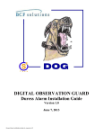
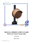
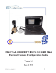
DIGITAL OBSERVATION GUARD
Mini PIR Sensor Setup Guide
Version 1.2
June 3, 2013
DS-PIR-Mini-Kit-2-v1_manual-v1.2
Table of Contents
System Description ................................................................................................................................................................. 2
Setting up the Sensors ............................................................................................................................................................. 3
Connecting the Sensors to the Cameras .............................................................................................................................. 3
Mounting the Sensors for Ground Use................................................................................................................................ 3
Mounting the Sensors on a Wall ......................................................................................................................................... 4
Mounting the Sensors on a Pole .......................................................................................................................................... 5
Configuring the Alarm Inputs on the DOG Base Station ....................................................................................................... 5
Alarm Display During Operation............................................................................................................................................ 6
Contact Info ............................................................................................................................................................................ 7
Table of Figures
Figure 1: Mini PIR Sensor Kit with Military Grade Case ...................................................................................................... 2
Figure 2: Mini PIR Sensor Kit Identification Label................................................................................................................ 2
Figure 3: Connecting PIR Sensor to Camera .......................................................................................................................... 3
Figure 4: Mounting PIR Sensor for Ground Use .................................................................................................................... 4
Figure 5: Wall Mounting PIR Sensor ..................................................................................................................................... 4
Figure 6: Pole Mounting PIR Sensor ...................................................................................................................................... 5
Figure 7: Find Alarm Configuration Menu ............................................................................................................................. 5
Figure 8: Set Alarm Inputs for Normally Open ...................................................................................................................... 6
Figure 9: Sensor Alarm Indicators .......................................................................................................................................... 6
1
System Description
The DOG Mini PIR (Passive Infrared) Sensor is a rugged small form factor sensor ideal for low profile
perimeter protection in both indoor and outdoor environments. The PIR sensor provides a second independent
intrusion detection capability to the DOG Base Station’s video motion detection in assisting the operator. The
PIR sensor detects the motion of an object that emits infrared radiation such as a human body. The PIR
provides both day and night time detection capabilities. The typical range performance for the PIR sensor to
detect a human sized target is 80-100m. Alarms generated by the PIR sensor are sensed in the DOG Standard
Camera Module or DOG Remote Module and transmitted to the base station up to 500m via the CAT-5
infrastructure.
The DOG Mini PIR Sensor Kit is an accessory kit for the DOG system. Each DOG Mini PIR Sensor kit Camera
kit contains 2 mini PIR sensors along with the necessary mounting hardware and associated accessories as
shown in the figure below.
Figure 1: Mini PIR Sensor Kit with Military Grade Case
Each case can be identified by a decal just above the handle as shown in the figure below.
Figure 2: Mini PIR Sensor Kit Identification Label
2
Setting up the Sensors
With the DOG system, all sensors are paired with cameras to provide direct visual assessment of each alarm.
The PIR sensors receive their power from the DOG camera units (either standard or thermal) and transmit their
alarms back to the DOG Base Station via the camera units also. The sensors plug into the sensor ports located
on the remote module associated with every DOG camera.
Connecting the Sensors to the Cameras
To connect the sensor to the camera module, simply remove the cap on the remote module sensor port as shown
in the figure below. Line up the pins (and notch) on the sensor connector and push the sensor connector into the
mating connector on the camera module. Twist the ring at the end of the sensor connector to lock and seal the
connector in place.
Figure 3: Connecting PIR Sensor to Camera
Mounting the Sensors for Ground Use
To mount the PIR sensors for ground use it is recommended to use the provided ground stakes. The ground
mounting stake consists of two pieces. The larger diameter stake is pounded into the ground using a hammer,
preferably a rubber mallet or rubber tipped hammer to prevent damage to the stake. Next attach the PIR sensor
to the smaller diameter stake by using the thumbscrew attached to the side of the sensor with the threaded hole
at the top of the mounting stake. Make sure to fully tighten the thumbscrew securely attaching the sensor to the
stake. The thumbscrew can be loosened once the mounting procedure is complete to tilt the sensor at the
desired angle. Slide the smaller stake with the sensor attached into the larger stake. Adjust the sensor to the
appropriate height and tighten the thumbscrew on the larger stake to secure the sensor.
3
Figure 4: Mounting PIR Sensor for Ground Use
Mounting the Sensors on a Wall
To wall mount the PIR sensor it is recommended to use the provided universal bracket. Mount the bracket to a
wall or vertical surface by driving screws into the mounting holes onto the back of the bracket into the
mounting surface. Then align the built in thumbscrew on the sensor with the threaded hole in the pedestal
mounted on the top of the wall bracket. Tighten the thumbscrew until the sensor holds itself up at the desired
angle.
Figure 5: Wall Mounting PIR Sensor
4
Mounting the Sensors on a Pole
To pole mount the PIR sensor it is recommended to use the provided universal bracket. Mount the bracket to a
pole by wrapping two wire ties through the wall mount bracket holes and around the pole. Make sure to pull the
wire ties tight to securely fasten the bracket to the pole. Next screw in the sensor into the side of the pedestal
mounted on top of the wall bracket. Adjust the sensor to the desired angle and tighten the thumbscrew until the
sensor holds itself.
Figure 6: Pole Mounting PIR Sensor
Configuring the Alarm Inputs on the DOG Base Station
Once the sensors are connected the DOG Base Station, the software must be configured to support normally
open alarm inputs. To get to the alarm input configuration screen click on the Event icon from the main menu
and then select the Per Channel Config menu as shown in the figure below.
Figure 7: Find Alarm Configuration Menu
Select the channel that you would like to configure in the Channel Select list and then select N/O in the Alarm
In list. Press the ESC key on the DVR front panel or click on the red circle with the X in the upper right hand
corner if you are using a USB mouse, in order to save the settings and escape to the next higher level menu.
Repeat this operation for each channel that you would like to configure. When finished, push the ESC button
repeatedly all the way back to the main menu.
5
Figure 8: Set Alarm Inputs for Normally Open
Alarm Display During Operation
During operation with the sensor, there are two ways to monitor the sensor alarms. There is a red alarm LED
in-line with the sensor connector cable. When the sensor is triggered the LED will light up as seen in the figure
below. Also if the DOG Base Station DVR has been configured properly, a red A will appear on the screen
when there is a sensor alarm as seen in the figure below. A red M will appear during a video motion detection
event.
Figure 9: Sensor Alarm Indicators
6
Contact Info
For questions or support please see our website at: www.bcfsolutions.net or contact: [email protected],
703-956-9088.
For user manual or other technical downloads go to the customer tab on the website and login with the
following: user: customer password: 2004-S4Tech
7