1
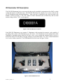
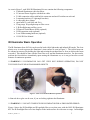
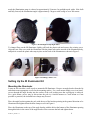
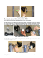
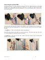
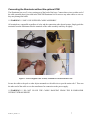
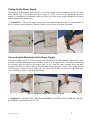
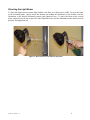
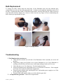
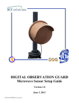
DIGITAL OBSERVATION GUARD
ILLUMINATOR KIT MANUAL
Version 1.3
June 3, 2013
DI-Kit-v2_manual-v-1.3
0
Table of Contents
IR Illuminator Kit Description...................................................................................................................... 2
IR Illuminator Basic Operation .................................................................................................................... 3
Setting Up the IR Illuminator Kit ................................................................................................................. 4
Mounting the Illuminator .......................................................................................................................... 4
Mounting the optional Photocell Switch Box (PSB) ................................................................................ 5
Connecting the optional PSB .................................................................................................................... 6
Connecting the Illuminator without the optional PSB .............................................................................. 7
Setting Up the Power Supply.................................................................................................................... 8
Connecting the Illuminator to the Power Supply ..................................................................................... 8
Directing the Light Beam ......................................................................................................................... 9
Bulb Replacement ....................................................................................................................................... 10
Troubleshooting .......................................................................................................................................... 10
Contact Info ................................................................................................................................................ 11
Replacement Parts ...................................................................................................................................... 11
Table of Figures
Figure 1: DOG IR Illuminator Kit Decal ...................................................................................................... 2
Figure 2: DOG IR Illuminator Kit ................................................................................................................ 2
Figure 3: Clear Lens and Focus/Defocus Operation..................................................................................... 3
Figure 4: IR Floodlight and Spotlight Filters ............................................................................................... 4
Figure 5: Installing a Filter Cover ................................................................................................................ 4
Figure 6: Mounting Bracket Use .................................................................................................................. 5
Figure 7: PSB Components and Positioning ................................................................................................ 5
Figure 8: Installing the PSB wing nut........................................................................................................... 5
Figure 9: Connecting the PSB to the Illuminator and PSB Extension Cable ............................................... 6
Figure 10: Connecting the PSB Extension Cable to the Illuminator Cable Assembly and Strain Relief..... 6
Figure 11: Connect Supplied Cable Assembly to Illuminator and Strain Relief to Pole ............................. 7
Figure 12: Mounting the Power Supply........................................................................................................ 8
Figure 13: Illuminator Cable to Power Supply Connection ......................................................................... 8
Figure 14: Horizontal and Vertical Beam Adjustment ................................................................................. 9
Figure 15: Changing the bulb. .................................................................................................................... 10
DI-Kit-v2_manual-v-1.3
1
IR Illuminator Kit Description
The DOG IR Illuminator kit is an accessory kit that can be installed in conjunction with a DOG or other
system that requires an IR light source. The DOG IR Illuminator kit consists of two cases; each case has
two IR illuminators and associated hardware. Each case can be identified by the decal just above the
handle as shown in Figure 1. The “DI” stands for DOG illuminator and is followed by the kit serial
number along with the “A/B” case designator.
Figure 1: DOG IR Illuminator Kit Decal
Each DOG IR Illuminator case contains 2 illuminators with associated accessories, each capable of
providing either visible or IR illumination over 300 meters. The illuminators can be configured in either
floodlight or spotlight modes using the IR filter covers or by twisting the ratcheted base to focus or
defocus the beam. Several bulbs of varying wattages are provided (100w, 75w, 50w) so that illumination
levels can be further controlled. The IR Illuminator Kit can be seen in Figure 2 below.
Figure 2: DOG IR Illuminator Kit
DI-Kit-v2_manual-v-1.3
2
As seen in Figure 2, each DOG IR Illuminator Kit case contains the following components:
• 2 infrared illuminators with clear filters
• 2 Universal Power Supplies with built-in cables
• 2 100ft connection cables with built in connectors and on/off switches on each end
• 2 mounting brackets (8” right angle brackets)
• 4 wide-range hose clamps
• spare bulbs (2 each 100w and 50w)
• 2 long range IR spotlight snap-on filter covers
• 2 IR floodlight snap-on filter covers
• 2 Photocell Switch Boxes (PSBs, optional)
• 2 PSB extension cords (optional)
• 2 sets PSB mounting hardware (optional)
• 1 DOG IR User Manual
IR Illuminator Basic Operation
The IR illuminator from S4 Tech can be used in both visible light mode and infrared (IR) mode. The clear
plastic cover is used to protect the illuminator’s inner surface as seen in Figure 3. The visible beam can
be widened or narrowed by holding the light and twisting the ratcheted base to focus or defocus the beam
as needed. This should be done with the clear filter cover and the illuminator turned on. For best results,
perform the focus/defocus immediately upon turning the illuminator on, as it can get hot after several
minutes of continuous operation.
***WARNING*** ILLUMINATOR CAN GET VERY HOT DURING OPERATION, DO NOT
TOUCH OR PLACE NEAR FLAMMABLE OBJECTS
Figure 3: Clear Lens and Focus/Defocus Operation
A faint red dot or glow can be seen, if you are looking right into the illuminator.
***WARNING*** DO NOT STARE INTO IR ILLUMINATOR FOR A PROLONGED PERIOD
Figure 4 shows the IR floodlight and IR spotlight filter covers that come with the DOG IR Illuminator
Kit. The IR floodlight filter cover has dimples on the inside surface for wide area coverage. In floodlight
DI-Kit-v2_manual-v-1.3
3
mode the illumination range is reduced to approximately 50 meters. In spotlight mode with a 100w bulb
and fully focused, the illumination angle is approximately 5 degrees with a range of over 300 meters.
Figure 4: IR Floodlight and Spotlight Filters
To change filters on the IR illuminator, lightly pull back the plastic tabs and remove the existing cover.
Align the new filter cover with the illuminator with the plastic tabs on the outside of the illuminator body,
and push it on until the plastic tabs snap in place on the back of the illuminator as shown in Figure 5.
Figure 5: Installing a Filter Cover
Setting Up the IR Illuminator Kit
Mounting the Illuminator
Locate an area on either a wall or pole to mount the IR illuminator. Remove an angle bracket from the kit
and obtain some appropriate screws for the mounting surface. For a wall mount simply screw in at least 2
screws through the angle bracket into the surface of the wall, making sure that a good grip is achieved.
For a pole mount, screws may be driven into the pole in a similar manner to a wall mount or if not
possible or practical, the included hose clamps may be used.
Place the angle bracket against the pole with the top of the bracket pointing in the general direction to be
illuminated and tighten down the hose clamps as seen in Figure 6.
Place the illuminator on the top of the angle bracket with the bolt at the bottom of the illuminator passing
through the hole in the center of the angle bracket. Place nut onto the bolt and tighten down.
DI-Kit-v2_manual-v-1.3
4
Figure 6: Mounting Bracket Use
Mounting the optional Photocell Switch Box (PSB)
Remove the PSB, PSB extension cord, mounting bolt, and wing nut from the kit.
Place the PSB on the top of the mounted angle bracket with the mounting hole in the PSB’s mounting
arm over the mounting hole in the angle bracket behind the installed illuminator, and insert the mounting
bolt through the holes. Make sure that the PSB points at a right angle to the light to prevent reflections.
Figure 7: PSB Components and Positioning
Once the PSB is in position with the mounting bolt inserted, place the wing nut onto the end of the
mounting bolt and tighten it down.
Figure 8: Installing the PSB wing nut
DI-Kit-v2_manual-v-1.3
5
Connecting the optional PSB
The illuminator has two (2) wires coming out of the back of the base. Connect these wires to the mating
terminals on the PSB. Connect the other pair of PSB wires to the end of the PSB extension cable
assembly that is provided in the DOG IR Illuminator kit. Do not use any other cables or wires as they
may damage the bulbs.
Figure 9: Connecting the PSB to the Illuminator and PSB Extension Cable
Connect the other end of the PSB extension cable assembly to the IR illuminator cable assembly that is
also provided in the DOG IR Illuminator kit. Do not use any other cables or wires as they may damage
the bulbs.
***WARNING*** ONLY USE SUPPLIED CABLE ASSEMBLIES
Secure the cable to the pole with cable ties to provide strain relief. Then run the other end of the cable
over to the transformer for connection to the power supply.
***WARNING*** DO NOT LEAVE THE CABLE HANGING FROM THE ILLUMINATOR
WITHOUT STRAIN RELIEF
Figure 10: Connecting the PSB Extension Cable to the Illuminator Cable Assembly and Strain Relief
DI-Kit-v2_manual-v-1.3
6
Connecting the Illuminator without the optional PSB
The illuminator has two (2) wires coming out of the back of the base. Connect these wires to either end of
the cable assembly that is provided in the DOG IR Illuminator kit. Do not use any other cables or wires as
they may damage the bulbs.
***WARNING*** ONLY USE SUPPLIED CABLE ASSEMBLY
All terminals are compatible regardless of color and the connection order doesn’t matter. Simply push the
terminals from the illuminator into the terminals of the cable assembly until they fit tightly.
Figure 11: Connect Supplied Cable Assembly to Illuminator and Strain Relief to Pole
Secure the cable to the pole or other object mounted to with cable ties to provide strain relief. Then run
the other end of the cable over to the transformer for connection to the power supply.
***WARNING*** DO NOT LEAVE THE CABLE HANGING FROM THE ILLUMINATOR
WITHOUT STRAIN RELIEF
DI-Kit-v2_manual-v-1.3
7
Setting Up the Power Supply
The universal IR Illuminator power supplies as seen in the figure below, can operate with any AC input
from 100-240VAC. They produce an output voltage of 15VDC at up to 9.5A. Mounting the power
supply is accomplished by installing screws on either side of the power supply through the mounting
holes as shown in the figure below.
***WARNING*** The power supply can get hot with extended operation and it is recommended to
place or mount it onto a thermally conductive surface (such as metal or cement) if possible.
Figure 12: Mounting the Power Supply
Connecting the Illuminator to the Power Supply
The power supply has two (2) 15VAC output wires coming out of it with terminals. Connect these wires
to either end of the Illuminator Cable Assembly as shown in the figure below. The order of connecting
the terminals does not matter as the output power is AC. Push the female terminal inside the male
terminal until there is a snug fit. Plug in the transformer to the appropriate voltage source, make sure the
IR illuminator is connected on the other end, and turn on the switches at each end of the Illuminator
Cable Assembly in order to turn on the illuminator.
Figure 13: Illuminator Cable to Power Supply Connection
***WARNING*** DO NOT USE THIS TRANSFORMER TO POWER 12VDC ITEMS OR CHARGE
BATTERIES – DAMAGE MAY OCCUR
DI-Kit-v2_manual-v-1.3
8
Directing the Light Beam
To direct the light beam turn on the light with the clear filter on so the beam is visible. To move the beam
in the horizontal plane, simply loosen the bottom nut holding the illuminator to the bracket, turn the
illuminator to the desired horizontal position, and tighten the nut. To move the beam in the vertical
plane, simply loosen the nut on the side of the illuminator base, turn the illuminator to the desired vertical
position, and tighten the nut.
Figure 14: Horizontal and Vertical Beam Adjustment
DI-Kit-v2_manual-v-1.3
9
Bulb Replacement
To change the bulb, simply hold the main body of the illuminator and twist the ratcheted base
counterclockwise as if you were defocusing the beam. Continue to twist until the main body comes off of
the base. Examine the bulb visually. If bad discard and replace with new bulb from kit. Make sure not to
touch the bulb with bare hands, use a tissue or cloth to prevent any finger oil from contaminating the
bulb, reducing its operational life span.
Figure 15: Changing the bulb.
Troubleshooting
1. The illuminator does not turn on.
• Check that the switches on each end of the Illuminator Cable Assembly are in the ON
position.
• Temporarily remove the IR filter cover on the illuminator to see if the illuminator is
working, as the IR filter will block most visible light making it hard to tell if it is on.
• Check the fuse to see if it is burnt out. If so then replace the fuse.
• Swap the illuminator unit with another one to see if the bulb is burnt out. If the swapped
unit works, then replace the bulb in the original unit.
• Swap the power supply (after checking the fuse) with another power supply to see if the
power supply has gone bad.
• Swap the cable with another cable to see if the cable has gone bad.
2. A component has gone bad. Contact S4 for replacement.
DI-Kit-v2_manual-v-1.3
10
Contact Info
For questions or support please see our website at: www.bcfsolutions.net or contact:
[email protected], 703-956-9088.
For user manual or other technical downloads go to the customer tab on the website and login with the
following: user: customer password: 2004-S4Tech
Replacement Parts
The following replacement parts may be ordered for the DOG IR Illumination Kit. Credit card orders are
accepted. Please contact S4 for order information.
Part No.
DI-TFPS-15VAC
DI-CA-100
DI-LT-170
DI-ISF-170
DI-IFF-170
DI-BLB-50
DI-BLB-75
DI-BLB-100
DI-RCASE-v1
Description
IR Illuminator Power Supply
Cable assembly, 100ft, 14AWG, with switches on both ends
Illuminator spotlight with clear filter cover
IR Spotlight Filter
IR Floodlight Filter
IR Illuminator bulb – 50 watts
IR Illuminator bulb – 75 watts
IR Illuminator bulb – 100 watts
Optional military grade heavy duty transport case.
Cost USD
375.00
250.00
350.00
220.00
220.00
40.00
40.00
40.00
800.00
* Prices are as of April 12, 2010 and are subject to change based on availability and material costs.
DI-Kit-v2_manual-v-1.3
11