1
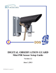
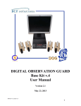
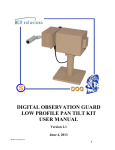
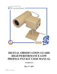
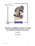
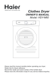
DIGITAL OBSERVATION GUARD
THERMAL CAMERA KIT MANUAL
Version 1.2
June 6, 2013
DT-Kit-1/2-v1_manual-v1.2
0
Table of Contents
Thermal Camera Kit Description.................................................................................................................. 2
Thermal Camera Basic Operation ................................................................................................................ 2
Thermal Camera Mounted on Remote Module ............................................................................................ 3
Thermal Camera Separated from Remote Module ....................................................................................... 5
Tripod Mounting the Thermal Camera ..................................................................................................... 5
Wall Mounting the Thermal Camera ........................................................................................................ 6
Pole Mounting the Thermal Camera ........................................................................................................ 8
Connecting Separated Thermal Camera to Remote Module .................................................................... 9
Adjusting the Thermal Camera ................................................................................................................... 10
Focusing Thermal Camera Image ............................................................................................................... 12
Care & Maintenance ................................................................................................................................... 12
Troubleshooting .......................................................................................................................................... 12
Contact Info/Tech Support ......................................................................................................................... 13
Replacement Parts ...................................................................................................................................... 13
Table of Figures
Figure 1: Thermal Camera Kit with Military Grade Case ............................................................................ 2
Figure 2: Thermal Camera Kit Identification Label ..................................................................................... 2
Figure 3: Basic Thermal Camera Module .................................................................................................... 3
Figure 4: Collocated Mounting Assembly Parts ........................................................................................... 3
Figure 5: Surface Mounting DOG Thermal Camera with Wood Screws ..................................................... 4
Figure 6: Attaching and Adjusting the Thermal Camera to DOG Camera Unit .......................................... 4
Figure 7: Attaching 14-Pin Circular Connector to the Back of the Thermal Camera .................................. 5
Figure 8: Attach Power and Data Cables to DOG Camera Unit .................................................................. 5
Figure 9: Pole Mount Assembly Parts .......................................................................................................... 6
Figure 10: Pole Mounting Procedure ............................................................................................................ 6
Figure 11: Wall Mount Assembly Parts ....................................................................................................... 7
Figure 12 Thermal Camera Bracket Assembly Procedure ........................................................................... 7
Figure 13: Attaching the Tripod Ball Head and Thermal Camera ............................................................... 8
Figure 14: Wall Mount Assembly Parts ....................................................................................................... 8
Figure 15: Pole Mounting Procedure ............................................................................................................ 9
Figure 16: Attaching 14-Pin Circular Connector to the Back of the Thermal Camera .............................. 10
Figure 17: Power/Data and Video Connections ......................................................................................... 10
Figure 18: Adjusting Thermal Camera with the Portable Video Viewfinder ............................................. 11
Figure 19: Adjusting Thermal Camera Rotation and Tilt ........................................................................... 11
Figure 20: Focusing Thermal Camera ........................................................................................................ 12
DT-Kit-1/2-v1_manual-v1.2
1
Thermal Camera Kit Description
The DOG Thermal Camera Kit provides rugged small form factor thermal cameras for covert zero-light
operations with the DOG system. The thermal cameras allow for covert viewing of personnel in zero light
conditions out to 300m, with vehicles at over twice that distance. The thermal cameras are
environmentally resistant and connect to the DOG CAT-5 infrastructure in the same way as other DOG
cameras. A DOG thermal camera can be mounted to the remote camera module or separated via a 10ft
adapter cable. The DOG thermal cameras may also be directly mounted to the DOG High Performance
PTZ camera as an accessory.
The DOG Thermal Camera kit is an accessory kit for installation with the DOG Base Kit. Each DOG
Thermal Camera kit contains 2 remote camera modules, 2 thermal cameras, and all associated accessories
as shown in the figure below.
Figure 1: Thermal Camera Kit with Military Grade Case
Each case can be identified by a decal just above the handle as shown in the figure below.
Figure 2: Thermal Camera Kit Identification Label
Thermal Camera Basic Operation
Each rugged thermal camera module is connected to the control station via a single standard CAT-5 LAN
cable which delivers both video and power up to 500m. Power to the thermal camera modules is provided
DT-Kit-1/2-v1_manual-v1.2
2
via the DOG Base Station. Installation of the rugged thermal camera requires mounting the Remote
Camera Module to a wall, pole, or surface, and connecting a single standard CAT-5 cable with RJ-45
connector through the weather-resistant connector. Then mount and connect the thermal camera to the
Remote Camera Module using either the 2ft (local) or 10ft (remote) thermal camera cable. In cases
where the thermal camera module is connected to the DOG High Performance PTZ camera, the Remote
Camera Module is not necessary. Once connected, the user will be able to display and record live video,
and perform motion detection for the thermal camera through the DOG Base Station. The basic thermal
camera module assembly is shown in Figure 3.
Figure 3: Basic Thermal Camera Module
Thermal Camera Mounted on Remote Module
For collocated thermal camera mounting begin by unpacking the Remote Camera Module with the
attached tripod, thermal camera, 2ft cable, and mounting hardware as shown below in Figure 4.
Figure 4: Collocated Mounting Assembly Parts
Start by mounting the Remote Camera Module, options include wall, surface, or pole mounting the
thermal camera. For a sturdy wall or surface mount, (Figure 5) screw the Remote Camera Module into
the surface using the appropriate type of screws for the specific surface material. For cement surfaces use
the appropriate cement anchors with pre-drilled holes. Ensure that all four screws are through the upper
and lower mounting holes, making sure that the thermal camera module is firmly mounted before
attaching the thermal camera.
DT-Kit-1/2-v1_manual-v1.2
3
Figure 5: Surface Mounting DOG Thermal Camera with Wood Screws
Next screw the thermal camera onto the Remote Camera Module ball head until the ball head screw is
tight. The thermal camera’s tilt and rotation angle can be adjusted by loosening the knob on the side of
the ball head and adjusting the thermal camera’s orientation and retightening the ball head knob.
Figure 6: Attaching and Adjusting the Thermal Camera to DOG Camera Unit
Once the thermal camera has been screwed down to the Remote Camera Module, the thermal camera
power and video connections need to be made. As shown in Figure 7 below, start by removing the
protective cap from the back of the thermal camera. Take the 2ft connector cable and align the 14-pin
circular connector (using the key/keyhole) to the back of the thermal camera and screw the connector on
until the connector is firmly tightened.
DT-Kit-1/2-v1_manual-v1.2
4
Figure 7: Attaching 14-Pin Circular Connector to the Back of the Thermal Camera
Next, lift the small protective cover from the 3-pin power/video connector on the side of the Remote
Camera Module as shown below in Figure 7. Grasp the power/video cable and line up the 3-pin male
connector with the 3-pin female connector on the side of the Remote Camera Module as shown below.
Push the cable connector into the Remote Camera Module connector and twist the locking ring on the
edge of the cable connector clockwise to fasten it. The Thermal Camera Module is now ready to be
connected to the DOG Base Station (refer to DOG Base Kit User Manual).
Figure 8: Attach Power and Data Cables to DOG Camera Unit
Thermal Camera Separated from Remote Module
For covert or separated thermal camera mounting begin by selecting which installation type will be used
(tripod, wall, or pole mounting).
Tripod Mounting the Thermal Camera
For a tripod mount begin by unpacking the Remote Camera Module with the attached tripod, thermal
camera, 10ft cable, and mounting hardware as shown in the figure below.
DT-Kit-1/2-v1_manual-v1.2
5
Figure 9: Pole Mount Assembly Parts
Begin by screwing the tripod ball head onto a sturdy tripod. Once the ball head is securely fashioned
attach the thermal camera to the tripod as shown in the figure below. Attach the 10ft. thermal camera
cable to the back of the thermal camera and run the cable to the Remote Camera Module.
Figure 10: Pole Mounting Procedure
Wall Mounting the Thermal Camera
To wall mount the thermal camera begin by unpacking the Remote Camera Module with the attached
tripod ball head, thermal camera, 10ft cable, wall/pole mount bracket (3 pieces), and mounting hardware
as shown in the figure below.
DT-Kit-1/2-v1_manual-v1.2
6
Figure 11: Wall Mount Assembly Parts
Begin by assembling the three piece bracket. Screw the ‘U’ shaped base piece into the wall surface with
the raised edges against the wall using the two inside holes on the bracket. Make sure to use the
appropriate type of screws for the specific surface material. For cement surfaces use the appropriate
cement anchors with pre-drilled holes. With the ‘U’ shaped base piece securely fastened to the wall,
attach the two remaining bracket pieces using the captive fasteners as shown.
Figure 12 Thermal Camera Bracket Assembly Procedure
DT-Kit-1/2-v1_manual-v1.2
7
After the bracket assembly is mounted to the pole attach the recently removed tripod ball head to the
bracket assembly as shown below. Once the ball head is mounted and securely tightened to the bracket
attach the thermal camera. It is important to keep one hand on the thermal camera at all times during the
installation process as the camera will not be fully secured until the ball head thumbscrew is re-tightened.
Connect the thermal camera to the DOG Remote Module and perform any fine adjustments to the camera
orientation repeating the steps described above.
Figure 13: Attaching the Tripod Ball Head and Thermal Camera
Pole Mounting the Thermal Camera
To wall mount the separated thermal camera begin by unpacking the Remote Camera Module with the
attached tripod ball head, thermal camera, 10ft cable, wall/pole mount bracket (3 pieces), and mounting
hardware as shown in the figure below.
Figure 14: Wall Mount Assembly Parts
Begin assembling the three piece mounting bracket as shown in the figure below. Make sure to fully
tighten each of the captive screws. Once the pole mounting bracket is fully assembled it can be wire tied
DT-Kit-1/2-v1_manual-v1.2
8
to a pole using a minimum of two wire ties or hose clamps. With the bracket securely attached to the
pole attach the tripod ball head to the end of the mounting bracket using the remaining captive fastener.
The thermal camera can now be screwed onto the tripod ball head and connected to the thermal camera
cable.
Figure 15: Pole Mounting Procedure
Connecting Separated Thermal Camera to Remote Module
Once the thermal camera has been mounted or placed in its operational position, the power and signal
connections need to be made. As shown in the figure below, start by removing the protective cap from
DT-Kit-1/2-v1_manual-v1.2
9
the back of the thermal camera. Align the 14-pin circular connector to the back of the thermal camera
(using the key/keyhole) and screw the connector on until the connector is firmly tightened.
Figure 16: Attaching 14-Pin Circular Connector to the Back of the Thermal Camera
Lift the protective cover from the power/video connector on the side of the Remote Camera Module as
shown below in Figure 17. Grasp the power/video cable and line up the 3-pin male connector with the
female connector on the side of the Remote Camera Module. Push the cable connector into the Remote
Camera Module connector and twist the locking ring clockwise to fasten it as shown below. The Thermal
Camera Module is now ready to be connected to the DOG VDP (refer to DOG Base Kit User Manual).
Figure 17: Power/Data and Video Connections
Adjusting the Thermal Camera
Once the Remote Camera Module has been installed in its final mounting position, the CAT-5 cable from
the DOG Base Station is attached using the procedure discussed in the DOG Base Kit User Manual, and
the camera is powered up. Once powered up, the camera can be aligned with the target area in two ways.
Alignment can be achieved by either viewing the video straight from the DOG Base Station monitor or
using the optional portable video viewfinder to see exactly where the thermal camera is pointing.
Viewing the thermal camera on the DOG Base station will require two operators. The first operator will
watch the thermal camera video display at the DOG Base station and communicate with a second
operator in the field the proper directions to align the thermal camera. The optional portable video
DT-Kit-1/2-v1_manual-v1.2
10
viewfinder allows a single operator to align and focus the thermal camera directly in the field as shown in
the figure below.
Figure 18: Adjusting Thermal Camera with the Portable Video Viewfinder
To align and adjust the thermal camera, loosen the tripod ball head thumbscrew as shown in the figure
below. The thermal camera can now be adjusted so that the correct viewing angle can be achieved. Once
the camera is pointing in the desired location re-tighten the tripod ball head screw, locking the camera in
place.
Figure 19: Adjusting Thermal Camera Rotation and Tilt
The thermal camera is a very high performance and expensive component and it is extremely important to
make sure once all adjustments have been made that the tripod ball head is fully screwed on and tightened
and secure so that the camera will not come loose.
*** IMPORTANT***
The thermal camera contains very sensitive electronics, which are not intended for viewing of direct or
indirect (reflected) sunlight. The unit is intended for non-horizon exposure looking downward from the
intended mounting plane. Exposure to sunlight, even for very short periods of time, may permanently
damage the camera.
DT-Kit-1/2-v1_manual-v1.2
11
Focusing Thermal Camera Image
After the thermal camera has been connected and powered up, the thermal camera image might be out of
focus. As shown in the figure below, simply turn the end of the lens clockwise and/or counterclockwise
to adjust the image focusing until a crisp image appears on the monitor screen or through the portable
video viewfinder.
Figure 20: Focusing Thermal Camera
Care & Maintenance
•
•
•
The optical surface of the thermal camera lens should only be cleaned when it is visibly dirty.
Care should be taken to avoid touching the exposed lens face. Skin acid left behind with
fingerprints can be damaging to coatings and lens substrates.
o First use a jet of air or blow across the surface of the lens to remove any sand or
abrasive particles before cleaning.
o If oil, water spots, or fingerprints form on the optical surface, clean as soon as possible
using a soft cloth and mild neutral soap diluted with lukewarm distilled water,
followed by reagent grade isopropyl alcohol or acetone swab.
o Dust can also be removed gently using an alcohol or acetone swab.
Thermal Camera (whether powered On or Off) is not intended for viewing of direct or indirect
(reflected) sunlight. The camera unit is intended for non-horizon exposure looking downward
from the intended mounting plane. Exposure to sunlight, even for very short periods of time,
may permanently damage the camera.
The thermal camera unit is not intended to operate submerged in water. However, the thermal
camera is designed to withstand exposure to rain or high humidity.
Troubleshooting
The camera does not operate when first connected to the CAT-5 cable:
• Test the CAT-5 cable to see if it or the connector is bad
• Use a known good piece of CAT-5 cable to test the camera.
• Swap the 2ft or 10ft cable to see if that is the problem.
The camera image is blurry.
• Visually inspect the camera lens for external dust or internal condensation.
• If there is dust or condensation on the lens, use a lint free cloth or wipe to clean it off.
• If there is no visible dust or condensation on the lens, then refocus the lens per the
Change/Focus Lens procedure described above.
DT-Kit-1/2-v1_manual-v1.2
12
•
If none of these actions work, then contact S4 Tech.
The camera image is too dark or light on the screen and very little detail can be seen.
Turn the brightness up/down on the DOG Base Station Monitor (per the DOG Base Kit user
manual) until the image is sharper and more detail can be seen.
VDP does not power up properly when all four cameras are plugged in – the video is noisy
or black. Unplug all remote camera units and power up the VPD. With the VPD still powered
on, plug the remote cameras back in one at a time.
Video image comes and goes on the monitor. Try moving the CAT-5 cable around near the
connectors on both the camera end and the base station end. If the video fluctuates with the cable
movement then the cable is going bad.
Contact Info/Tech Support
For questions or support, please see our website at: www.bcfsolutions.net or contact:
[email protected], 703-956-9088.
For user manual or other technical downloads go to the customer tab on the website and login with the
following: user: customer password: 2004-S4Tech
Replacement Parts
The following replacement parts may be ordered for the DOG Pan-Tilt Kit. Credit card orders are
accepted. Please contact S4 for order information.
Part No.
DRP-RTSU
DRP-CAM-TH
Description
Rugged Remote Camera Module
Thermal Camera
DRP-CAM-TH-TPD
DRP-CAM-TH-CBL-2
DRP-CAM-TH-CBL-10
DRP-CAM-TH-CBL-PTZ
Short Thermal Camera Tripod
2 ft Remote Thermal Camera Cable
10 ft Remote Thermal Camera Cable
3 ft Pan-Tilt Thermal Camera Cable
.
DT-Kit-1/2-v1_manual-v1.2
13