1
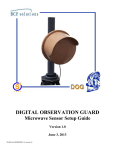
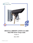
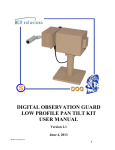
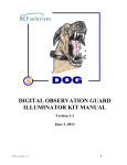
DIGITAL OBSERVATION GUARD Mini
Thermal Camera Configuration Guide
Version 1.1
June 6, 2013
DMT-Kit-1/2-v1_conf_guide-v1.1
0
Table of Contents
System Description ....................................................................................................................................... 2
Connecting the Hardware ............................................................................................................................. 2
Installing the Serial Port Driver .................................................................................................................... 5
Configuring the Thermal Cameras with the Application Software .............................................................. 6
Setting Camera Config Parameters........................................................................................................... 7
Calibration ............................................................................................................................................ 7
Black Hot/White Hot ............................................................................................................................ 8
Display Pattern ...................................................................................................................................... 8
Image Orientation ................................................................................................................................. 9
Power Up Settings ................................................................................................................................ 9
Reset Power Up Settings..................................................................................................................... 10
Reset to Factory Settings .................................................................................................................... 10
Get Serial Number .............................................................................................................................. 10
Error Message ..................................................................................................................................... 10
Close Application ............................................................................................................................... 11
Troubleshooting .......................................................................................................................................... 11
Contact Info/Tech Support ......................................................................................................................... 11
Table of Figures
Figure 1: DOG Mini-thermal Camera Configuration Kit ............................................................................. 2
Figure 2: Connecting the 12VDC power supply .......................................................................................... 3
Figure 3: Connecting the Mini-thermal Camera ........................................................................................... 3
Figure 4: Connecting the wrist video viewer ................................................................................................ 4
Figure 5: Connecting the USB to a Laptop .................................................................................................. 5
Figure 6: Config Application Screen ............................................................................................................ 6
Figure 7: Select and Config Ports ................................................................................................................. 7
Figure 8: Setting the Pattern Colors.............................................................................................................. 9
Figure 9: Reading and Clearing and Error Msg.......................................................................................... 10
Figure 10: Close the Application ................................................................................................................ 11
DMT-Kit-1/2-v1_conf_guide-v1.1
1
System Description
The DOG Mini-thermal Camera Configuration Kit allows the user to change the default camera settings
such as image polarity, image orientation, video color mode, and calibration time on the DOG minithermal camera. The calibration kit consists of a camera calibration box, 12VDC power adapter, and a
software installation CD. The mini-thermal camera is provided in the DOG Scout Base Kit. It is highly
recommended to use the wrist video viewer also provided in the DOG Scout base kit to allow the user to
see the changes made to the mini-thermal in real time.
Figure 1: DOG Mini-thermal Camera Configuration Kit
Connecting the Hardware
Begin by plugging the 12VDC power adapter provided with the Mini-thermal camera calibration kit into
a 110-VAC wall outlet or surge protector. Next plug the 12VDC power adapter jack into the black
receptacle on the camera calibration box.
DMT-Kit-1/2-v1_conf_guide-v1.1
2
Figure 2: Connecting the 12VDC power supply
Connect the mini-thermal camera to the camera calibration box making sure the connector is firmly
seated onto the mini-thermal camera. At this point the mini-thermal camera will power on.
Figure 3: Connecting the Mini-thermal Camera
Use the wrist viewer provided with the DOG Scout Base Kit to connect to the BNC port on the side of the
camera calibration box. Turn the wrist video viewer on and the mini-thermal camera’s video will be
displayed on the screen.
DMT-Kit-1/2-v1_conf_guide-v1.1
3
Figure 4: Connecting the wrist video viewer
DMT-Kit-1/2-v1_conf_guide-v1.1
4
Finally, plug the USB cable into the laptop or computer that will be used to configure the mini-thermal
camera.
NOTE: It is important that the USB cable is plugged into the laptop or computer only after the camera
calibration box has been powered on, otherwise the laptop will not be able to properly sync up and
communicate with the mini-thermal camera.
Figure 5: Connecting the USB to a Laptop
Installing the Serial Port Driver
The CD that is included in the DOG Mini-Thermal Camera Configuration Kit contains software drivers
used to install the hardware on a windows PC along with application software that runs on a windows PC
for configuring the thermal cameras. The driver software is used to configure the USB port of a
Windows PC or Laptop so it can communicate with the hardware.
It is recommended that the whole DOG Mini-Thermal Camera Config folder is copied from the CD to
a folder on the hard drive of the Windows computer or laptop that will be used for the camera
configuration. The software can be run directly from the CD, but may run slower on some machines.
Next follow the instructions which are included as PDF files in the USB Driver Installation Guides sub
folder which is inside the hardware drivers folder under the DOG Mini-Thermal Camera Config
folder. Look up the instructions for the appropriate Windows operating system on your machine
(Windows XP, Windows Vista, or Windows 7).
The driver file that is referenced by the installation guides is under the hardware drivers folder and is
called:
CDM20814_WHQL_Certified.zip
Open the appropriate guide and follow the instructions to install the driver.
DMT-Kit-1/2-v1_conf_guide-v1.1
5
Configuring the Thermal Cameras with the Application Software
Once the thermal camera interface driver has been successfully installed on a Windows PC or laptop and
the mini-thermal camera is attached to the unit, you are ready to launch the application software. Simply
go to the config software subfolder under the DOG Mini-Thermal Camera Config folder and double
click on the Mini-Thermal Config Utility icon.
*** if you move the icon to the desktop or other location, make sure and place the Mini-Thermal Config
Utility.pdb file in the same location.
Once the application is launched the following screen will appear on your pc.
Figure 6: Config Application Screen
*** IT IS IMPORTANT THAT YOU ALWAYS CLICK ON A SELECTION TO HIGHLIGHT IT OR
IT WILL NOT BE RECOGNIZED BY THE SOFTWARE
Click on the Information icon shown as a blue circle with a white letter i inside in the upper right corner
of the application window to get help. Simply click in the help window to make it disappear.
Click on the Get Ports button and see what active COM port shows up in the adjacent text box. If two
COM ports show up together such as COM3 COM7 then use the second one in the list.
DMT-Kit-1/2-v1_conf_guide-v1.1
6
Select that same COM port from the Set Port drop down list just below, by using the arrows to scroll to
the right COM port and then clicking on the COM port so that it is highlighted in blue as seen below.
Figure 7: Select and Config Ports
Once the port has been selected, click on the Config Port button and you will see the port configuration
parameters show up in the yellow box to the right and the Open Port button will be active. Once that
happens then click on the Open Port button and you will see the port status as “open” in the yellow box.
*** In order to reconfigure the port you must close the port first by clicking on the Close Port button
and then you can repeat the configuration operation.
Once the port has been successfully configured and open, then you may begin configuring the thermal
camera.
Setting Camera Config Parameters
Calibration
The camera calibration function is an important issue that should be addressed with this kit. The DOG
mini-thermal camera can be set for automatic calibration or manual calibration. The automatic
DMT-Kit-1/2-v1_conf_guide-v1.1
7
calibration can be set for every 2 minutes or every 15 minutes. Automatic calibration refreshes the
camera calibration frequently and can help sharpen/clarify the camera image. In some cases however the
automatic calibration can also set of video motion detection alarms, especially if the DOG system is set to
a high sensitivity level. If this occurs, nuisance alarms will be generated every time the automatic
calibration occurs every 2 or 15 minutes. If this is happening or if you simply want to avoid this
possibility then it is recommended to set the camera in the manual calibration mode. Even in manual
calibration mode the camera will automatically calibrate based on temperature changes, it just won’t
happen as often.
*** IT IS RECOMMENDED TO SET THE CAMERA TO MANUAL CALIBRATION MODE IF THE
CAMERA WILL BE USED WITH THE DOG’S VIDEO MOTION DETECTION CAPABILITY.
A manual calibration can be done with the software at any time by simply clicking on the Do Calibration
button.
Make sure the click on the Save as Power Up Settings button to insure that the camera stays in this mode
even after powering down.
Black Hot/White Hot
Simply click on the White Hot or Black Hot buttons in order to toggle between these two modes.
If you want the camera to keep this setting even after powering down, click on the Save as Power Up
Settings button to insure that the camera stays in this mode.
Display Pattern
The display pattern will cause different colors to be mapped to the temperature of the observed scene.
Select the color pattern by using the arrows in the drop down list box and clicking on the desired
selection. Once the desired selection is highlighted in blue, then click on the Set Pattern button as seen
below.
If you want the camera to keep this setting even after powering down, click on the Save as Power Up
Settings button to insure that the camera stays in this mode.
DMT-Kit-1/2-v1_conf_guide-v1.1
8
Figure 8: Setting the Pattern Colors
Image Orientation
The image orientation allows you to view the image upside down (Invert) or as a mirror image (Mirror)
or both. As with the pattern function above, simply use the arrows to select the image orientation in the
drop down list and click on the desired selection to highlight it blue. Once highlighted hit the Set Image
button. To go back to normal orientation simply select the Normal option.
If you want the camera to keep this setting even after powering down, click on the Save as Power Up
Settings button to insure that the camera stays in this mode.
Power Up Settings
The power up settings are the parameters that the camera is set to when it first powers up. The settings
that are made in the software will immediately take effect but will be wiped out when the camera is
powered down. If you want the current configuration that you have just created to persist after power
down then the Save as Power Up Settings button must be clicked.
DMT-Kit-1/2-v1_conf_guide-v1.1
9
Reset Power Up Settings
If you have changed the settings on the camera and would like to go back to the original settings that
existed when the camera first powered up, then click on the Reset Power Up Settings button.
Reset to Factory Settings
If you have changed the power up settings using the save power up settings button, but would like to
return back to the original factory settings then click on the Reset to Factory Settings button.
Get Serial Number
If you are contacting S4 Tech for support please click on the Get S/N button and record the serial number
of the camera before you contact us.
Error Message
If an error occurs a small display box will appear in the middle of the application with an error message.
Read the error message and then click on the Clear Error button as seen below to make the error box
disappear.
Figure 9: Reading and Clearing and Error Msg
DMT-Kit-1/2-v1_conf_guide-v1.1
10
Close Application
To close the application simply click on the small X in the upper right corner of the window as seen by
the small white cursor in the picture below.
Figure 10: Close the Application
Troubleshooting
1. Nuisance alarms are occurring every 2 or 15 minutes. Read the section on setting the camera
calibration mode above, and set the camera to manual calibration.
2. Wrist video viewer does not display image. Batteries may be low. Use the recharge the
batteries per the DOG Scout Kit user manual.
2. I need tech support. Get the camera serial number per the instructions above and the DOG kit
number that it came from, and contact S4 Tech per the directions below.
.
Contact Info/Tech Support
For questions or support, please see our website at: www.bcfsolutions.net or contact:
[email protected], 703-956-9088.
For user manual or other technical downloads go to the customer tab on the website and login with the
following: user: customer password: 2004-S4Tech
DMT-Kit-1/2-v1_conf_guide-v1.1
11