1
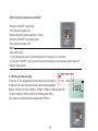
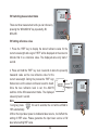
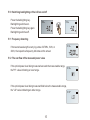
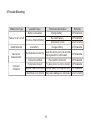
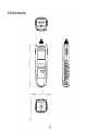
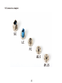
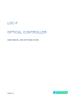
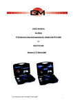
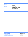
User’s
Manual
AQ2170
Optical Power Meter
User’s Manual
Yokogawa Meters & Instruments Corporation
IM AQ2170-01EN
1st Edition
Notes
1. The contents of this manual are subject to change without prior notice as a result of continuing
improvements to the instrument’s performance and functionality. The figures given in this manual
may differ from those that actually appear on your screen.
2. Every effort has been made in the preparation of this manual to ensure the accuracy of its
contents. However, should you have any questions or find any errors, please contact your nearest
YOKOGAWA dealer.
3. Copying or reproducing all or any part of the content of this manual without the permission of
YOKOGAWA is strictly prohibited.
Trademarks
1. Microsoft, Windows are either registered trademarks or trademarks of Microsoft Corporation in
the United States and/or other countries.
2. Adobe, Acrobat, and PostScript are trademarks of Adobe Systems Incorporated.
3. In this manual, the TM and R symbols do not accompany their respective registered trademark or
trademark names.
4. Other company and product names are registered trademarks or trademarks of their respective
holders.
1st Edition: October 2012(YMI)
All Rights Reserved, Copyright© 2012, Yokogawa Meters & Instruments Corporation
Product Registration
Thank you for purchasing YOKOGAWA products.
YOKOGAWA provides registered users with a variety of information and services.
Please allow us to serve you best by completing the product registration form accessible
from our homepage.
http://tmi.yokogawa.com/
Safety Information
Warnings!
Do not short-circuit the batteries. Excessive electrical current may cause personal injury due to
fumes,electric shock or equipment damage.
Do not operate the equipment near hot objects, in hot environments, in dusty/ humid atmosphere or when
condensation is present on the equipment. This may result in electric shock , product malfunction or poor
performance.
Safety Precautions
The general safety precautions described herein must be observed during all phases of operation.If the
instrument is used in a manner not specified in this guide ,the protection provided by the instrument may
be impaired .YOKOGAWA assumes no liability for the customer's failure to comply with these
requirements.
!
The following symbole are used on this instrument.
Improper handing or use can lead to injury to the user or damage to the instrument.
This symbol appears on the instrument to indicate that the user must refer to the user's manual
For special instructions. The same symbol appears in the corresponding place in the user's manual to
identify those instructions. In the manual, the symbol is used in conjunction with the word "WARNING" or
"CAUTION".
WANNING
Calls attention to actions or conditions that could cause serious or fatal injury to the user,
and precautions that can be taken to prevent such occurrences.
CAUTION
Calls attention to actions or conditions that could cause light injury to the user or cause
damage to the instrument or user's data, and precautions that can be taken to prevent
such occurrences.
Calls attention to information that is important for proper operation of the instrument.
Note
Table of contents
1. Introduction ......................................................................................................................1
2. Warranty ...........................................................................................................................2
3. Preparing for Operation .....................................................................................................3
4. Specifications ...................................................................................................................5
5. Operation .........................................................................................................................7
6. Trouble Shooting .............................................................................................................16
7. Recommended Replacement Parts ...................................................................................17
8. Maintenance ...................................................................................................................18
9. Outline drawing ...............................................................................................................19
10. Connector adapter .........................................................................................................20
1 Introduction
18 8 8 nm
REF
-.8.8.8.8
The AQ2170 series are full featured mini sized and lightweight
optical power meters designed for use with an optical Light source
to perform optical loss measurements on optical fiber cables.
optical connections to the AQ2170 are made via the universal
adapter interface on the top of the unit.
The instrument has 7 working wavelengths(The AQ2170H is 5
wavelengths) to totally satisfy your needs.
It can be extensively used in telecommunication projects and
other situations where optical power of wavelengths close to
infrared ray needs to be measured.
1
2 Warranty
Exclusions
The warranty on your equipment shall not apply to defects resulting from the following:
Unauthorized repair or modification
Misuse, negligence, or accident
Returning Product
To return product, you may contact YOKOGAWA to obtain additional information if necessary.
To serve you better, please specify the reasons for the return.
All delivery and mails should be sent to the following nearest YOKOGAWA dealer.
2
3 Preparing for Operation
3.1 Unpacking the instrument
Packing material
We suggest that you keep the original packing material. Using the original packing material is your
guarantee of protecting the instrument during transit.
Checking the package contents
The standard accessories of AQ2170 are as follows:
No.
1
2
3
4
5
6
7
8
Product Name
Main Unit
Dry battery AAA
Connector Adapter(FC,SC,LC,Ø1.25 ferrule,Ø2.5 ferrule)
Carrying Case
Operation Guide(Paper)
User's Manual(CD)
Protector
Strap
Qty.
1
4
Each 1
1
1
1
1
1
Checking for damage in transit
After unpacking the instrument, check to see whether it was damaged in transit. This is particularly
likely if the outer casing is clearly damaged. If there is damage, do not attempt to operate the
instrument or to repair it without authorization. Doing so can cause further damage and you may
lose your warranty qualification.
3
3.2 Discharged batteries
There is a battery indicator on the screen to show the remaining charge. There are four possibilities the
indicator may show, full, with 2 blacks, with 1 black and empty. If an empty battery indicator means the
power is almost out please replace it with a new one. To replace the batteries, please remove the
battery plate on the back of instrument.
When the battery charge is extremely low to supply the necessary power, the instrument will
automatically switch off.
Note
To eliminate the possibility of acid leakage, please take out the battery if the unit is not used for a
long time.
4
4 Specifications
4.1 Sensor Specifications
Model
Wavelength Range (nm)
AQ2170
AQ2170H
850/1300/1310/1490/1550/1625/1650 nm
1310/1490/1550/1625/1650 nm
Detector
InGaAs
Applicable Fibers Type
Light emitted from SM( ITU-T G.652) ,
Light emitted from SM( ITU-T G.652),
GI( 50/125 µm) ,GI( 62.5/125 µm) optical fiber
optical fiber
Optical Connector
FC, SC, LC, Ø 1.25 ferrule, Ø 2.5ferrule
Power Range(dBm)
Noise Level(dBm)
Uncertainty under standard conditions
1
1
-70~+10 dBm
-50~+26 dBm
-60 dBm
-40 dBm
±5%
±5%
Power level: 100 μW(-10dBm); CW, Wavelength: 1310, Spectral width: 5 nm or less (1310 nm),
ambient temperature: 23 ±2°C,Optical fiber: SM (ITU-T G.652), Optical connector: FC/PC, Polarization condition: Excluding
Polarization dependence,Removing/Installing connector adapter : Including,1 year aging
5
4.2 General Specifications
Model
AQ2170
Displayed Resolution
AQ2170H
0.01dB(>-60dBm),0.1dBm(≤-60dBm)
0.01dB(>-40dBm),0.1dBm(≤-40dBm)
Displayed Unit
Absolute values:dBm, mW, µW Relative values: dB
Modulation Mode
CW,CHOP(270Hz,1kHz,2kHz)
Measurement Interval
Approximately150 ms
Measurement mode
Absolute value measurement
Relative value measurement:
Relative value measurement relative to a set reference value
Relative value measurement based on a displayed measurement
Power supply
Dry and Rechargeable Battery AAA
Battery life
1
Approximately 40 hours
Power saving
Power turns off automatically when there is no key inputfor
Battery check
Battery indicator
approximately 10 minutes (this function can bedisabled)
Environmental conditions
Operating temperature range:-10~50℃,
Operating humidity range:20~80%
Storage temperature range:-20~+70℃(no condensation)
Dimensions and weight
1
2
Storage humidity range:5~95%(no condensation)
63(W)×116(H)×35(D) mm, Approximately160 g
Continuation Measurement, using alkaline dry cells, at 23 ℃ ±2℃
2
A protector is removed.
Note
Specifications are at 23℃±2℃ uncless otherwise noted.Optical connector: FC/PC
6
5 Operation
5.1 Installing the Batteries
Turn the screw on the rear panel with a coin or other flat object to remove the cover, then install the
batteries.
Turning the screw locks/unlocks the cover as shown in the figure.
Unlock
Lock
Insert four AAA batteries into the holder following the polarity markings. Always close the cover
after installing batteries.
If the low battery indicator, you must change the batteries immediately. The instrument runs for
approximately forty hours when using alkaline AAA batteries (depending on operating conditions).
7
Note
Use the correct size and type of battery specified by the manufacturer of your device.
Keep battery contact surfaces and battery compartment contacts clean by rubbing them with a clean
pencil eraser or a rough cloth each time you replace batteries.
Remove batteries from a device when it is not expected to be in use for several months.
!
Make sure that you insert batteries into your device properly, with the + (plus) and - (minus) terminals
aligned correctly.
CAUTION:
Some equipment using more than three batteries may appear to work properly even if one battery is
inserted incorrectly.
Store batteries in a dry place at normal room temperature.
Most batteries will provide dependable long life even after five years of storage in these conditions. Do
not refrigerate batteries, this will not make them last longer.
Extreme temperatures reduce battery performance. Avoid putting battery-powered devices in very warm
places.
8
5.2 Attaching a Connector Adapter
A specialized connector adapter is required for connecting an optical connector to the instrument. Choose
an adapter that matches the optical connector you will use.
The screw mechanism that attaches the connector adapter to the instrument is of precision manufacture.
Please handle all parts with care so as not to damage the screw threads.
Do not allow dirt to come into contact with the optical input section. Dirt or other
foreign particles can influence measurement. Attach the protective cap to the
optical input connector when not in use.
(1) Remove the optical input connector cap.
(2) Attach a connector adapter.
The connector adapter screws onto the connector; hold the adapter upright to align
the threads properly, then turn to tighten.
Do not attach the connector adapter at an angle, and do not forcibly turn it any
further after it has initially tightened. Doing so can damage the screw threads or
sensor.
Note
It is recommended to clean the inside of the connector adapter using a dedicated
swab or other cleaner and anhydrous alcohol.
Dedicated swabs for cleaning optical adapters are available from NTT, including
the “CLETOP Stick-Type” (NTT-ME).
9
5.3 Attaching/Detaching a Protector
(1) Please insert in the upper part to a protector.
(2) Please insert the lower part in a protector.
Note
We recommend that you replace the
protector when damaged.
10
5.4 Keypad
No.
Key
>2s PERM
1
ON
OFF
>2s SET
2
REF
5
Switches instrument on/off. Long keypress over 2 seconds
while powering on is to activate the instrument without Auto-off function.
Short keypress to display reference level of present test wavelength.
Long Key press over 2seconds to set a new reference level of present
test wavelength.
Selects measurement wavelength in sequence of 850/1300/1310/1490/
1550/1625/1650nm(AQ2170H:1310/1490/1550/1625/1650
3
4
Function
dBm/
dB/mW
Switches measurement unit among dBm,dB,mW
Switch back lighting on/off
11
5.5 LCD
Wavelength
Auto-off
18 8 8 nm
Reference
Frequency
Battery Charge
REF
-.8.8.8.8
270Hz 1kHz 2kHz
Power value
12
Measurement Unit
5.6 Turning the instrument on and off
Press the “ON/OFF” key briefly.
The instrument powers-on.
Please check the battery capacity if it fails.
Press the “ON/OFF” key briefly again.
The instrument powers-off.
Note
Auto-off function
1. The instrument powers off automatically if no keypress in 10 minutes.
2. Press the “ON/OFF” key for about 2 seconds to power on the instrument with “Auto-off”
function deactivated.
1625
1550
5.7 Setting the wavelength
1650
Press the “λ” key repeatedly until the desired wavelength is
850
1300
displayed. You can select fromseven optional wavelengths:
850nm,1300nm,1310nm,1490nm, 1550nm,1625nm,1650nm(AQ2170)
1310nm,1490nm,1550nm,1625nm,1650nm(AQ2170H)
The instrument defaults to the wavelength 1550nm.
13
1490
13 1 0
nm
- 2 0.0 0
AUTO-OFF
1 3 1 0 nm
25.08
5.8 Switching measurement mode
There are three measurement units you can choose by
pressing the “dBm/dB/mW” key repeatedly, dB,
dBm,mW.
5.9 Setting reference value
18 8 8 nm
1. Press the “REF” key to display the stored reference value for the
current wavelength and a sign of “REF” will be displayed on the screen to
indicate that it is a reference value. The displayed value only lasts 1
second.
2. Press and hold the “REF” key over 2 seconds to store the presently
measured value as the new reference value for the
current wavelength. During the process the “REF” sign 1 3 1 0
short
flashes twice on the screen and buzzer sound is heard.
- 2 0.0 0 keypress
Once the new reference level is set, the AQ2170
switches to the dB measurement mode. The displayed
value only lasts 1 second.
Note
1.Long key press
for over 2 seconds, the unit will be shifted to
REF
"dB" automatically.
2.When the input laser power is modulated laser source, it will affect the
setting of REF value. Please guarantee the input laser source is CW
laser when setting REF value.
REF
-.0.00
nm
REF
AUTO-OFF
14
1 3 1 0 nm
5.88
5.10 Switching backlighting of the LCD on and off
Press the backlighting key.
Backlighting switches on.
Press the backlighting key again.
Backlighting switches off.
1 3 1 0nm
1 3 1 0nm
-5.0
-5.0
5.11 Frequency detecting
If the tested wavelength is carrying a tone of 270Hz, 1kHz, or
2kHz, the respective frequency indicates on the screen
1 3 1 0nm
-20.00
1kHz
270Hz
5.12 The overflow of the measured power value
If the optical power level being measured exceeds the measureable range,
the"HI" value indicating an over range.
If the optical power level being measured falls below the measureable range,
the "LO" value indicating an under range.
1 3 1 0nm
1 3 1 0nm
L0
15
6 Trouble Shooting
Malfunction Type
Failure to turn on/off
On&off disorder
Inaccurate
measurement
Improper
indication
Recommended solution
Change battery
Re-install battery
possible Cause
Battery exhausted
Reverse-installed battery
(Still doesn’t work)
Change battery
Low battery
Contaminated connector
Swab the dust by using an alcoholimpregnated thin cotton swab
Remarks
DIY Abailable
DIY Abailable
Return to factory
DIY Abailable
DIY Abailable
Connector unfitted
Re-install the connector
DIY Abailable
Try later while it is not too humid
Humid environment
DIY Abailable
Magnetic field environment Stay far away from magneticfield
DIY Abailable
Metal dust environment May cause damage on mainboard Return to factory
16
7 Recommended Replacement Parts
YOKOGAWA guarantees the AQ2170 for the period and under the conditions of the product
warranty.
Under the conditions of the warranty, the following consumable parts and parts with limited service
lives are excluded.
For part replacement, contact your nearest YOKOGAWA dealer.
Consumables
We recommend that you replace the following parts at the intervals listed below.
Part Name
Recommended Replacement Interval*
Notes
Battery cover (Screw lock)
Approx. 500 times
Purchase and replace
Universal and connector adapters Approx. 1000 times
Purchase and replace
* The recommended replacement interval can vary greatly depending on the operating
environment and the frequency of use. The above intervals are estimates.
17
8 Maintenance
Please cover the protective dust cap once you finish using.
It is a good idea to clean the connector and the instrument when they get dirty through use.
Optical cleaning pads and anhydrous alcohol is recommended. And please be careful not to
get the detergent inside the instrument.
Periodic calibration is an effective means of keeping the instrument performing correctly for
a long time and of detecting malfunctions at an early stage.
We recommend that you have the AQ2170 calibrated once a year.
Prohibitions against Actions that Cause Leaking, Ignition and Explosion.
Do not leave it in a location that is exposed to direct sunlight.
Do not throw the battery into fire or heat it.
When you put the battery in the battery case, make sure that the battery is facing the right direction.
If you will not use the battery for an extended period of time, remove it from the AQ2170 and store it in
a dry place.
18
9 Outline drawing
19
10 Connector adapter
SC
LC
FC
Ø2.5
Ø1.25
20