1
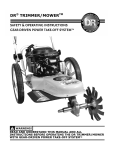
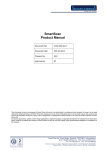
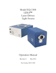
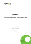
Fibre-Optic Hydrophone System: User Guide Fibre-Optic Hydrophone System CONTENTS Unpacking the Fibre-optic hydrophone system ............................................................................................ - 3 Package contents ...................................................................................................................................... - 3 Introduction .................................................................................................................................................. - 4 Safety information..................................................................................................................................... - 4 Overview of operating principles .............................................................................................................. - 4 Handling the sensor................................................................................................................................... - 4 Installation ..................................................................................................................................................... - 4 Software installation ................................................................................................................................. - 5 Connecting to an oscilloscope ................................................................................................................... - 6 Connecting a sensor downlead ................................................................................................................. - 6 Mounting the hydrophone ........................................................................................................................ - 6 Operation ...................................................................................................................................................... - 7 Initialisation ............................................................................................................................................... - 7 Using the hydrophone ............................................................................................................................. - 10 ITF display ............................................................................................................................................ - 11 Frequency Response (Freq. Response) ............................................................................................... - 12 Temperature measurement (Temperature) ....................................................................................... - 13 Changing the sensor ............................................................................................................................ - 14 Troubleshooting .......................................................................................................................................... - 15 Visible light source fault checking ........................................................................................................... - 15 Attach the visible light source ............................................................................................................. - 15 Check the hydrophone tip ................................................................................................................... - 15 Check for bends ................................................................................................................................... - 15 Check for breaks .................................................................................................................................. - 16 Verify the Interferometer Transfer function ............................................................................................... - 16 Warranty ..................................................................................................................................................... - 17 APPLICATIONS ADVICE AND TECHNICAL ASSISTANCE ................................................................................. - 17 - Fibre-Optic Hydrophone System UNPACKING THE FIBRE-OPTIC HYDROPHONE SYSTEM PACKAGE CONTENTS 1. 2. 3. 4. 5. 6. 7. 8. 9. Fibre-optic Hydrophone System control unit. Fibre-optic hydrophone mount. Two fibre-optic hydrophone sensors (minimum). USB A-B system connection lead. IEC mains power lead. Cletop-S fibre optic connector cleaner cassette. HUX Cleaner (in adapter connector cleaner). (Optional) JDSU Visual Fault Locator. This instruction manual. 3. 1. 2. 4. 6. 5. 7. 8. Fibre-Optic Hydrophone System INTRODUCTION The following document provides an outline for the installation and use of the Precision Acoustics Fibre-optic Hydrophone System. It is assumed that the reader has knowledge of making measurements with other hydrophone devices (such as PVDF needle and membrane hydrophones). Further information on making acoustic measurements with hydrophones can be found on our website (http://www.acoustics.co.uk). In addition, Precision Acoustics Ltd offer training courses covering many aspects of acoustic measurement techniques and practices. SAFETY INFORMATION The fibre-optic hydrophone system (FOHS) contains a class 1M laser product emitting invisible laser radiation. The optical output power from the connector on the front panel of the system does not exceed 1 mW at an optical wavelength of 1550 nm and as such should be “eye safe”. However care should always be taken to avoid looking directly at the output when the laser is on. WARNING: DO NOT VIEW DIRECTLY THE OUTPUT FROM THE SYSTEM WITH OPTICAL INSTRUMENTS e.g. microscopes and other magnifying optics. OVERVIEW OF OPERATING PRINCIPLES The fibre-optic hydrophone works on the principle of interferometric detection of changes in the optical thickness of a thin polymer film at the tip of the optical fibre sensor downlead. Changes in the thickness may be induced acoustically (through the acoustic pressure) or thermally. The system is capable of differentiating between the two and making simultaneous measurements of both. A full description of the operating principles can be found in “A Fabry-Perot fibre-optic ultrasonic hydrophone for the simultaneous measurement of temperature and acoustic pressure”, P Morris et aI, J. Acous. Soc. Am. Vol 125(6) pp. 3611-3622, June 2009. HANDLING THE SENSOR The optical fibre used in the sensor downlead comprises a thin glass fibre (OD 125 m) surrounded with a thin acrylate primary buffer layer (OD 250 m) and encased in a flexible plastic jacket (OD 900 m). Optical fibre is very flexible in nature, however, it is important to remember that the light carrying part of the fibre is made of glass and careful handling is important to ensure the longevity of the sensor downlead. If the glass fibre is broken, light will no longer reach the sensing element and measurements will be impossible. In particular, when handling the fibre downlead the following guidelines should be observed: Avoid tight bends in the fibre to prevent sensor damage o Bend radii less than 10 mm should be avoided. Avoid knotting the fibre. o Tangles and knots in the fibre should be careful undone without pulling the fibre taut. When in use, ensure the fibre is kept clear of mechanical equipment (such as translation stages etc) so that it does not become entangled in moving parts. INSTALLATION Fibre-Optic Hydrophone System SOFTWARE INSTALLATION 1. 2. 3. 4. Connect the IEC mains inlet to the rear of the system and a mains socket. Connect the USB cable to the front of the system and to a spare USB socket on your PC. Ensure PC is switched on and running MS Windows (Minimum XP). Switch on the system (power switch on rear panel), if this is the first time the system has been plugged into the PC, the following may appear: 5. Click “Next” and follow the onscreen instructions. If other similar windows pop-up, run through these also. a. If any of the hardware installations fail at this point, don’t worry, just carry on with the rest of the installation. 6. Navigate to “My Computer” and double click on the drive named “FOH_System” (the drive letter will be system dependent): 7. Double click on “FOH 1.X.X.X Installer.exe”. This is a self extracting executable which will copy the necessary installation files to the PC and then install the system software. 8. Follow the on screen instructions to install the necessary National Instruments components. Finally, restart the PC when instructed to do so a. (On some PCs it may be necessary to unplug the hydrophone system for the PC to boot normally, if this is the case, a “system disc” error will be displayed asking you to remove the “non-system disc” and press any key to continue. If you receive this message, simply unplug the hydrophone system and press any key on the keyboard). 9. The system is now installed and ready for use. To run the control program, go to Start>All Programs>FOH Control>FOH Control. A desktop shortcut will also be created for your convenience. Fibre-Optic Hydrophone System CONNECTING TO AN OSCILLOSCOPE In order to make acoustic measurements, the hydrophone system must be connected to an oscilloscope via the “AC out” connector on the front panel. The system is designed to have an output impedance of 50 Ohm, thus an oscilloscope with a 50 Ohm input is required. If your oscilloscope does not have this facility, an inline terminator should be used. Note. Thermal measurement is made by the software, thus no additional connection is required for this function. CONNECTING A SENSOR DOWNLEAD Before using the system a sensor downlead must be connected to the adaptor on the front panel. To do this, remove the dust cap from the adaptor on the front panel and the connector on the sensor downlead. Using the supplied Cletop-S cleaning cassette, clean the tip of the fibre connector (by squeezing the handle and swiping the face of the connector across each of the exposed tape strips) and then carefully insert the connector into the adaptor, ensuring the key on the connector lines up with the notch on the adaptor. The connection to the downlead is optical. Thus it is vitally important that both the connector end-face and the adaptor remain clean. Any contamination of the interface between the sensor downlead and the system will lead to degradation of the acoustic sensitivity of the system. Please adhere to the following guidelines to ensure optimum performance of the hydrophone system. Clean the sensor connector prior to EVERY use. o Even if the sensor is only temporarily removed from the system, clean it again before it is reinserted. Avoid contamination of the connector o Always apply the dust-cap when the sensor is not attached to the system. o DO NOT allow the connector to get wet or submersed in water*. Avoid contamination of the adaptor o When the system is not in use, the adaptor dust cap should be attached at all times. o DO NOT insert anything other than a fibre connector into the adaptor. * If the connector is dropped into water or gets wet, allow to dry thoroughly and then use one of the supplied emergency optical wipes to clean the connector ferrule thoroughly. Allow to dry again and then use the Cletop-S cleaner prior to connecting the sensor to the system. Fibre-Optic Hydrophone System MOUNTING THE HYDROPHONE The fibre-optic hydrophone system is supplied with a removable mount compatible with Precision Acoustics Ltd needle hydrophone mounts. To load the hydrophone into the mount first detach the cone section from the shaft of the mount, then thread the fibre through the shaft. Remove the protective sleeve from the tip of the hydrophone and very carefully thread the tip through the cone sectionn. Screw the shaft section back onto the cone, just tight enough for the fibre to be gripped. DO NOT OVER-TIGHTEN THE SHAFT – doing so may damage the hydrophone. Similarly over tightening with no fibre installed will damage the cone section. OPERATION INITIALISATION Once the system is switched on, set up as described in the previous section and connected to a PC, the control software should be loaded by double clicking the desktop shortcut (or locating the item on the “Start menu”). This will initialize the system and bring up the following window: Fibre-Optic Hydrophone System The first time the software is run after the system has been switched on, the initialization may take up to 30 seconds, as the laser warms up. Once the initialization is complete, the “Status” indicator will turn green and the following page will be displayed: Fibre-Optic Hydrophone System Fibre-Optic Hydrophone System USING THE HYDROPHONE To make an acoustic measurement with the system, ensure a sensor is connected to the system and click “Begin”. The system will then bias the sensor ready for measurement. This takes approximately 3 – 5 s, during which time a progress bar will be displayed. Once biased the system is active and in the presence of an ultrasound field, the acoustic pressure wave is output from the “AC out” connector on the front panel. The following screen is then displayed: The status indicator in the top right of the screen shows: Status: o o o o The current system status: Dark Green – system is idle Bright Green – system is on and active Amber – system is on and monitoring, but tracking is not active Blinking yellow (in combination with either bright green or Amber) – System is monitoring and recording temperature changes o Red – an error has occurred. Inverting – If the acoustic signal is being inverted Locked – If the laser is locked to a channel Channel – Which channel the laser is currently operating at. Below the status indicator are the main system controls: Re-bias – Acquire the interferometer transfer function and optimize sensitivity Fibre-Optic Hydrophone System ITF – Show the last acquired interferometer transfer function Freq. Response – Show sensor frequency response Temperature – Begin temperature measurement acquisition End – End current measurement task and enter idle state (laser off). Which controls are visible depends on the current status of the hydrophone system. ITF DISPLAY Clicking on “ITF” in the main system controls causes the system to show the interferometer transfer function. The software display will change to the following: (ITF displayed in graph is representative of a typical ITF, however they do vary!) From the ITF display, it is possible to disable the automatic tracking of the bias point. This is not generally recommended. However, when tracking is disabled the laser can be manually tuned using the Channel up and down arrows. This feature may be useful if looking at highly non-linear fields, enabling the linear range of the sensor to be shifted towards higher peak positive pressures. For further information on the use of this function, contact Precision Acoustics Ltd. Clicking Save in the bottom right of this display will save the current ITF to disk. A dialogue box will pop-up asking for a filename and directory to which to save the ITF. Fibre-Optic Hydrophone System FREQUENCY RESPONSE (FREQ. RESPONSE) Clicking Freq. Response shows the frequency response of the hydrophone selected from the drop-down menu “Sensor”. Frequency response data for the sensors supplied with the system are stored on the system itself. To display the sensitivity of the selected sensor at a particular frequency, enter the desired frequency in the control below the graph (f (MHz)). The sensitivity in mV/MPa and the uncertainty in percent are then displayed alongside. If a value of frequency greater than the maximum calibration frequency is entered, the display will only show the sensitivity at the maximum frequency. To enter frequency response data for a new sensor, click New in the bottom right of the display. This will open a data entry window, where you can either load data from a file or add new data manually. (Note, this feature is not yet implemented in the software and will be added at a later date). Fibre-Optic Hydrophone System TEMPERATURE MEASUREMENT (TEMPERATURE) Click Temperature in the main control set to start a temperature measurement task. The temperature measurement begins the moment the Temperature control is clicked. Data is recorded at a rate of 200 samples per second and streamed directly to disk. However, only 60 seconds of the recorded data is ever displayed on the screen, once t > 60 s, the display will “roll” maintaining the most recent 60s worth of data only. At the end of a measurement click Save to convert the temporary stored data to a tab delimited text file for use in your choice of data display/manipulation software. A dialogue will appear asking for confirmation of filename and directory. A comment can also be added to the saved data. At any time, the measurement can be stopped (for closer inspection of the acquired data, for example) and or reset. Resetting will clear the temporary data store. AUX IN The front panel of the hydrophone system includes a BNC connector labeled “Aux in”. This is connected internally to an A-D card enabling external analogue signals to be recorded alongside any temperature measurements. This may be useful for the synchronization of temperature and pressure measurements if a “gate” signal is recorded to indicate the switching on/off of the ultrasound field. To enable/disable the aux input, click the Aux in switch at the top right of the graphic display. SYNC OUT Fibre-Optic Hydrophone System In addition to the Aux input, the hydrophone system provides a “Sync out” signal from the front panel. The sync output provides a square wave TTL signal with a low-high switch occurring for each measurement point on the temperature time curve. This signal is provided to facilitate the synchronous acquisition of acoustic waveforms and temperature rises. It is important to note that there is a low-high switch (i.e. rising edge) for each measurement point, but that some measurement points are recorded by the system as “not a number” (NaN). This is to minimize the effect of artefacts in the temperature measurement arising from the tuning of the laser during temperature acquisition. Synchronisation of temperature and pressure acquisitions is maintained by recording the time value of each measurement point/pulse, but recording NaN in the temperature measurement data when the measurement coincides with a laser tuning event. To enable/disable the sync output pulse, click the Sync out switch at the top right of the graphic display. CHANGING THE SENSOR If the sensor fails or is disconnected, the system will (typically) detect this, disable the laser, inform the user and return to the initial display. However, if the user wishes to change the sensor or disable the laser output for any reason, clicking the End button in the main controls will disable the laser and return to the software to the main screen. The sensor can then be changed and a new measurement task started. Fibre-Optic Hydrophone System TROUBLESHOOTING VISIBLE LIGHT SOURCE FAULT CHECKING The hydrophone is (optionally) supplied with a visible light source for fault checking and to aid alignment. If it is suspected that a sensor is broken, the visible light source can be used to verify this. ATTACH THE VISIBLE LIGHT SOURCE Once the visible light source is connected to the hydrophone and switched on, a red glow will be visible both at the tip of the fibre and where at the connector end. This is normal. CHECK THE HYDROPHONE TIP An undamaged hydrophone tip will glow slightly with the red light from the visible source. If the tip has been damaged, significantly more light will be visible leaving the hydrophone tip. CHECK FOR BENDS A bend in the fibre causes light to escape. All bends should be avoided, but the tighter the bend the more light is lost, and the higher the risk of breaking the fibre. Fibre-Optic Hydrophone System CHECK FOR BREAKS If the fibre is bent too far, it will snap internally. In this case all of the light will escape and a bright point of light will be seen through the yellow jacket. VERIFY THE INTERFEROMETER TRANSFER FUNCTION The interferometer transfer function of each sensor supplied with the system can be found on the hydrophone system at T:\Data\ITFs (where “T” is the drive letter associated with the fibre-optic hydrophone system – labeled FOH_System in “My Computer”). The data is saved in tab delimited text files and can be viewed in Excel or other such programs. If a damaged sensor is suspected, but the visible light source check was inconclusive, measure the ITF of the sensor (by selecting Begin and then ITF) and compare it to the file saved on the system. The function may shift along the x-axis (as a result of temperature changes) but the overall function shape should always remain the same. Any significant change in shape will likely lead to inaccuracy in acoustic measurement. Fibre-Optic Hydrophone System WARRANTY Products are covered against defect of manufacturing or workmanship only. Warranty period: Fibre probes 6 months, Control unit and accessories12 months. If a warranty claim is made on devices that have been calibrated at NPL London a charge will be made for the used part of the calibration (e.g. failure of fibre probe at 3 months charge for recalibration at NPL is 50% of calibration charge) APPLICATIONS ADVICE AND TECHNICAL ASSISTANCE Further advice and technical assistance can be obtained from our Applications Engineers Tel: + 44 1305 264669, Fax: + 44 1305 260866 email: [email protected] 3. Precision Acoustics Ltd December 2011 V 1.2 6. 9.