1
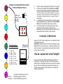
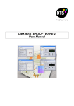
PC Software updates are available
for this product for free from –
www.daslight.com
RYGER
UKtm
This unit will function using either
DVC1 or DVC2 software-(recommended).
Always use the latest version and drivers.
Old software is not compatible with new drivers
or visa-versa, a pc using newer drivers will not
recognise a controller if using older software.
Software System Requirements
Microsoft Windows 98 or higher - 32bit PC only
DirectX ver.9 or higher
Minimum 500Mhz processor / 1.5Ghz preferred
256mb RAM / 512mb preferred
100Mb Free disk space
CD-Rom drive
USB 2.0 port
Video Requirements
DirectX 9 Compatible video card
64mb Video memory / 128 preferred for 3D visualisation
These are minimum system requirements, for using the 3D
visualisation program higher specs offer smoother visuals.
RYGER UK Ltd.
Oxfordshire
UK
www.rygeruk.com
FOOTLIGHT USB DMX
Universal Controller
For L.E.D. Parcans &
DMX Lighting Effects
User manual
Description
The Footlight USB DMX is a Universal PC programmable
controller for operating any manufactures DMX intelligent
lighting effect. Perfect for the latest range of L.E.D. Parcans.
6 individual shows, 512 DMX channels, stand-alone ability & a
built-in scheduler option for timed control of your shows.
Once shows are created on the PC using the Daslight software
supplied they are uploaded to the Footlight via the USB
connection. The controller is then designed to function without
the PC connected using the stand-alone feature.
More functionality and steps are also available if the unit is
controlled LIVE using the PC or laptop computer whilst
remaining connected via the USB terminal.
Getting Started
1. First you must install the Daslight DVC1 or DVC2 software
onto your PC – once this has been accomplished you
must then close the program if running. Should your
controller not be recognised please download the latest
software & drivers from www.daslight.com
2. Next plug the controller into the 9volt DC adaptor and turn
on, connect to PC via the USB connections – after a short
while the PC will recognise the hardware – proceed
through the install clicking OK to any install messages that
may appear.
3. Remember the USB port location on your computer and
always use this same port when reconnecting the
controller to avoid reinstalling the drivers.
4. Now start the DVC program to begin programming shows.
The Green LED on the controller will blink rapidly to
indicate a good USB connection & a Show Change is
now possible.
Specifications
DMX protocol Power supply Power Input connection USB connection DMX connection -
Industry standard 512 DMX
9 volts DC 500mA
2.1mm - Centre pin positive +
Industry Standard USB connector
Industry Standard 3 pin XLR
DMX out Channels 512 stand-alone channels of DMX out available
Amount of stand-alone steps available decrease with
increased amount of channels used.
WORKING OUT DIP SETTINGS
First work out your starting address for
the fixture (first slider number)
Dips 1, 2, 3, 4, 5, 6, 7, 8
Value 1, 2, 4, 8, 16, 32, 64, 128
Once you know the address number
simply add up the values to make the
number and switch those dips on only.
Eg.Parcan 3 below
Address 11 = values 8+2+1
DIP Switch settings
for 5 channel Parcans
Parcan 1 = dip 1 on
Parcan 2 = dip 2, 3 on
Parcan 3 = dip 1, 2, 4 on
Parcan 4 = dip 5 on
Parcan 5 = dip
Parcan 6 = dip
Parcan 7 = dip
Parcan 8 = dip
1, 2, 3 on
2, 4, 5 on
1, 2, 3, 4, 5 on
3, 6 on
DMX Connection viewed
from front of controller
PIN 2
Cold ( - )
PIN 1
Shield
PIN 3
Hot ( + )
IMPORTANT NOTE
Check your
Parcan manufacturers
instructions to identify
how many channels
(sliders) they are using.
The instructions given in this manual are
only a quick start guide.
Please read and familiarise yourself with the full set of
instructions that are a part of the Daslight software.
Also use the ‘Ryger DMX’ help videos on the CD & on
www.youtube.com (search for Ryger DMX)
Plan your scenes and steps carefully to save memory.
You don’t need to put too many steps into any one scene,
It is not always required for it to make an effective
lightshow.
Remember if you change what 1 fixture is doing it will
take the same amount of steps as if you change 8 or even
20 fixtures at the same time – so create a lot of movement
or lamp changes with each step.
Important Note
For detailed instructions on the use of the software and it’s
capabilities refer to the Daslight manual on the CD or access the
help menu from within the program. The following information is a
quick start guide. You need the program running to follow this next
part of the guide. When starting the software there is a flash
screen at the beginning that will notify you of a controller
connection if this displays ‘demo mode’ the controller has not
been found. Restart controller and restart software.
Connecting Fixtures / Effects
The Footlight USB DMX can be programmed without the fixtures
connected using the 3D visualiser program within the Daslight
software. However the easiest way to program shows is to connect
all of your DMX fixtures together in a ‘daisy chain’ and plug the
controller into the first fixture. Terminate the last fixture in the chain.
(Fixtures will work without termination but on long cable runs this
can cause sporadic problems with the functionality of the shows, it
is not usually a problem on short runs).
Use your fade and wait times to completely alter the
outcome of your lightshow.
EXPERIMENT & see what happens.
Save the main show and if you make a drastic mistake
simply open the last saved show again.
SAVE SHOWS – Regularly. Get into the habit of saving
your lightshows. PC’s are unpredictable at times & just
when you don’t need it – they lock up or crash.
Dip Switch and Address Settings
There is a library of fixtures (Scanlibrary) within Daslight that
contains most of the generic lighting effects on the market.
1.
2.
3.
4.
Click on setup tag on left-hand side of screen
Add a chosen Scanlibrary fixture by clicking the fixture
icon, browse the next screen until you locate your fixture
or a similar one that uses the same amount of channels.
Select your fixture and open it. The next box asks how
many fixtures of this type you are using ie: 4 scans. Put
the amount of fixtures in the box & click OK.
The dips and addresses will now be displayed, click on
each fixture in turn and set the dips as shown. (See
diagram on pages 7 & 10 for 5 or 6 ch parcan settings)
Adding More Fixtures
Simply add further fixtures by repeating the last procedures.
Dips are set – Now what?
1. Plug in all of the fixtures to the mains power supply and
allow them to run through their start up and reset
functions.
2. To test connect-ability push a slider up on each fixture in
turn and make sure they do something ie: open a shutter
or move a mirror etc.
All looks ok – How do I program?
1. Select the scene tab on the Left-hand side of the screen
2. Two windows will open – on the left-hand window click on
the ‘new scene’ & highlight it, rename the scene by Rightclicking the mouse when the ‘new scene’ is highlighted.
Type in a name that you will recognise easily.
3. Now on the Right-hand window you will see a ‘list of
steps’ the first one will be already shown so click on it.
4. Move the sliders on your chosen fixtures to all of the
desired locations ie: lamp on, gobo chosen, colour
selected, mirror position etc etc. This is your first step.
5. Click on the ‘add a new step’ icon, now move the sliders
to a new position, gobo, colour etc
6. Repeat the above procedure a few times to create the
movement within your fixtures.
7. At the top of the screen is a ‘Play Scene’ icon. Click on
this to run the scene. The lighting fixtures will operate but
probably too fast or to slow for your liking and will need
Wait and Fade times adding to the steps. A Wait time is
simply how long a lamp will stay at one position before
moving on & a Fade time is how long it will take to get to
the next position once it starts to move off to it.
Take the time to understand the
process of DMX programming
Add your scene
Rename your scene
Make your steps
Set your WAIT & FADE times
Test run the scene
Alter and correct mistakes
SAVE THE SHOW
Add another scene
Rename the new scene
Make your steps
ETC…….
ETC…..
Make lots scenes
Choose 6 for uploading
Allocate port numbers
SAVE THE SHOW
Go to Options & Stand-alone
Transfer to upload window
Write memory
DMX made SIMPLE…….
NOW USE THE FOOTLIGHT!
1
1
Example of a simple LED Parcan layout
6 Channel Showtec Parcans
9 volt
Adaptor
DMX Lead
Daisy Chained
To LED
Parcans
2
10.
11.
3
Footlight
6
7
8
Stop the scene from playing by clicking on the icon again
At the top of the steps window are Fade time and Wait
time icons. Select these and adjust the desired times up
or down and select ‘for all steps’ to begin with. This will
slow down or hold the lamps all at the same speed for all
of the steps. Re-play the scene for a moment. Stop the
scene again.
If a desired part of the step selection is not going to plan
simply highlight the step in question and reset the Wait or
Fade time of the individual step to suit your ideas.
Do not be tempted to put too many steps into a scene,
keep them short and simple for effective shows particularly if you are using the entry level controller. This
scene will become one button on the controller.
I now want - A New Scene
4
5
8.
9.
DIP Switch settings
for 6 channel Parcans
1 = dip 1 on
2 = dip 1, 2, 3 on
3 = dip 1, 3, 4 on
4 = dip 1, 2, 5 on
5 = dip 1, 4, 5 on
6 = dip 1, 2, 3, 4, 5 on
7 = dip 1, 3, 6 on
8 = dip 1, 2, 4, 6 on
120 ohm
Terminator
USB cable for
programming
LAPTOP
To construct a terminator use a 3 pin
XLR male plug with a 120 ohm
resistor soldered across pin 2 & 3
Simply click on the ‘create a new scene’ icon, located to the side
of the left-hand window.
RENAME the scene and carry on as before by adding the steps.
REPEAT this for six sets of scenes – maybe put a blackout in as
one of the scenes. You will upload 6 scenes to 6 buttons in total
on the entry level controller.
How do I upload them to the Footlight?
First you must allocate a different port setting to each of the
scenes that you are going to upload. In the Left-hand scenes
window there is a drop down menu that you can select for setting
the port. Click on the desired scene and where it states ‘none’
click this to gain access to the drop down menu. Change the
setting to a desired port.
Porting and Button Allocation
The Footlight USB DMX has 6 red buttons –
One Lightshow (scene) will be uploaded into each button (port).
All port numbers uploaded must be different.
REMEMBER –
Performing The Upload
If the upload fails, restart the controller and wait for the PC
to find it – Restart the software & the flash screen will briefly
notify you of a controller connection. You must see the
controller in this pop up. If ‘demo mode’ is displayed the PC
has lost it’s USB connection to the controller.
1.
The upload is performed by clicking on the options menu
on the toolbar at the top of the screen.
2.
Click on Stand-alone in the dropdown menu.
3.
Depending on the software version installed you will either
move the desired scenes from the L/H window across to
the R/H window or Drag and Drop the scenes down into a
series of boxes at the lower part of the screen. Make sure
each scene has a different port number allocated.
4.
Set the number of stand-alone channels (sliders) you are
using in total. Keep this as low a number as possible for
more steps to become available. (later software will do
this automatically)
5.
Click on WRITE MEMORY icon
6.
A window will pop up notifying you of a successful upload,
if it has failed, try again. If still unsuccessful it will be
because the USB connection has been terminated by
your PC. Restart the controller, wait for the PC to find it.
Restart the software, load the saved show and carry out
the upload.
The RED LED is the power on light & indicates the DMX is active
The GREEN LED is the SHOW CHANGE indicator & this
indicates the current state of the controller.
Blinking RAPIDLY means the controller is under PC control via
the USB connection, a change of the porting and shows is now
possible.
Blinking SLOWLY means the controller is disconnected from the
PC and is ready to use in STAND-ALONE mode.
(when pulling out the USB connection this can take up to 10
seconds to activate automatically, it will pause and blink when
ready)
Upon reconnecting the USB connection you may need to restart
the software for the program to locate the controller.
The following information is a guide on how to carry out the
upload from the PC and onto the controller.
WARNING – Save the show that you
have just made. If it crashes during
upload you will lose it.
7. Once uploaded the controller will work without the PC
connection.
You must wait until the Show Change Green LED blinks
slowly before the controller will operate stand-alone.