1
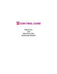
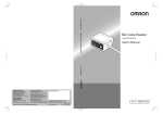
Specifications
Footlight FL-P1
Size
Weight
Sound
Power supply
Output
(W) 250mm x (D) 170mm x (H) 70mm
1.45Kg
Internal Mic
220-240Vac adaptor to 9volt DC on controller
DMX 512 protocol 64 channels
Dealer Stamp
Copyright Ryger UK 2010 ver0110
Made in England
www.ryger.co.uk
Ryger UK Ltd.
FL-P1
100 pattern Pre-programmed
DMX RGB LED Effects Controller
User Manual
Description
The Footlight series are easy to use multi-function light controllers.
This footlight is ideal for mobile DJ‟s, bands & fixed installations or marquee illumination etc.
This FL-P1 features full sound chase, blackout, 100 chase sequenced patterns, speed control,
two auto pattern modes, output dimming and RGB colour mixing for a preferred master flood.
It is designed to operate DMX enabled RED, GREEN, BLUE static LED fixtures, Parcans etc.
Minimal DMX knowledge is required by the user.
9
11
12
IMPORTANT
It is important that the set up instructions are fully read in this booklet as they will guide you through
the various processes to connect your Ryger LED fixture controller to your LED products.
13
6
4
7
5
10
14
8
Connections
Mains Input:
Is via the 9v 500mA DC transformer supplied with this product.
Outputs:
Outputs are made via DMX 512 standard 3 Pin XLR socket. Pin1 = shield, Pin2 = cold -, Pin3 = hot +
The serial port is for future PC support (not openly available at the moment)
Sound Input:
The controller has its microphone and does not require any external connections to source sound input
1
2
3
Setup
Read this fully - Minimal DMX knowledge is required by the user.
8 fixtures can be controlled separately with this unit.
All fixtures you use should ideally be of the same manufacture type or must operate on the same
RGB channels – check user manuals for this information if you are mixing different fixture types
(not advised without DMX knowledge).
The FL-P1 can be configured for 10 different profile types of LED parcans/bars/panels.
The list supplied will help you choose which type is required and give the corresponding code number
that you will need to use to configure the controller for first use.
PROFILE CODES FOR VARIOUS FIXTURES ARE SHOWN IN THE SEPARATE LIST.
To first configure the FL-P1 you need to hold down the FLOOD button & then power up the
controller, then release the button. The display will now show d0, d1, etc. Using the Blue UP and
DOWN Pattern buttons cycle through the options until the number in the display matches the required
profile of your fixtures.
Now press and release the FLOOD button again to restart the controller.
On powering up the chosen fixture code will flash briefly.
It will now remember this setting until such times as it is reset or the user changes it.
This can be easily changed to different makes by repeating the above procedure. Providing that all 8
fixtures use the same profile they will then operate correctly and access all 100 patterns within the unit.
1. BLACKOUT BUTTON
2. FLOOD OVERRIDE BUTTON
3. BANK CHANGE BUTTON
4. SPEED CONTROL
5. SOUND CONTROL
6. UP PATTERN BUTTON
7. DOWN PATTERN BUTTON
8. AUTO/MANUAL FUNCTION BUTTON
9. ANIMATION TYPE FUNCTION BUTTON
10. LED DISPLAY
11. MASTER DIMMER
12. RED FADER
(only used when setting up master flood)
13. GREEN FADER (only used when setting up master flood)
14. BLUE FADER (only used when setting up master flood)
15. 3 PIN DMX OUTPUT (on left side)
16. 9 VOLT 500Ma POWER SUPPLY INPUT (on right side)
17. Serial port (currently not used) (on right side)
Optional wall fixing kit available from Ryger
DMX VALUES AND SETTINGS
Fixture Codes
In order to gain the most from the controller all of the fixtures have to be assigned their own DMX
settings. This will either be with dip switches or a digital setting on your fixtures.
Most of the LED parcans that are on the market currently run on 4 or 5 DMX channels.
A channel for red, blue, green and occasionally one for the master dimmer & presets.
But the FL-P1 runs all fixtures as using 8 channels of DMX to incorporate the par-bars & panels and
such like that use more channels. So the address settings are always working from 8 channels.
Below is a guide on how to set your fixtures starting address or dip switches.
= DIP ON
= DIP OFF
DIPS SETTINGS
Fixture 1
1 2 3 4 5
The separate list of profile codes is a small selection of the most common fixture types.
For a detailed fixture list visit www.ryger.co.uk
d0, d1, d2, d3, d4, d5, d6, d7, d8, d9 are the options available. If you are unsure you can simply retry
every profile in turn with your fixture connected, restarting the controller each time. To check the
setting is correct hold down the BANK CHANGE button until „FA‟ appears in the display. You can
now operate the RGB sliders one at a time and see if the corresponding colour illuminates on your
fixture. If they all operate correctly then that is the profile to use, if they do not operate correctly then
try another profile number. Hold down the BANK CHANGE button to exit the „FA‟ setup.
DIGITAL
6
7
If you correctly identify an unlisted fixture to a profile please email the details to [email protected]
so that it can be added to the profile list. If you require a custom profile contact Ryger for a costing.
8
001
Fixture 2
1 2 3
Fixture 3
1 2 3
Fixture 4
1 2 3
Controlling Patterns
4
4
4
5
5
5
6
6
6
7
7
7
8
009
Blackout button
017
Flood button
8
8
025
4
5
6
7
8
Fixture 6
1 2 3
4
5
6
7
8
Fixture 8
1 2 3
The FLOOD override button (2) will flood all fixtures in one easy movement, simply push
the button to flood and push again to release back to the previously running sequence.
This FLOOD button can be user programmed with a favourite flood pattern.
Bank change button
Fixture 5
1 2 3
Fixture 7
1 2 3
The BLACKOUT button (1) provides an instant blackout of all lights connected to this unit.
It will override all other programs and black out all fixtures that are in use.
4
4
5
5
6
6
7
7
8
8
033
041
The BANK change button (3) has the function of allowing a user to change through the
various different BANKS manually at the the touch of a button. This will jump in turn to the
pre-selected pattern in each of the banks at each press of the button.
Adjust Pattern Speed or Sound Chase:
This is done by using the blue ANIMATION (9) button - each time this is depressed the associated
LED indicator will show what mode of stepping the unit is utilizing.
049
LED off = Default factory preset speeds
LED on = Manual Speed adjustable using the rotary (4)
LED blinking = Sound chase operating, adjust sound sensitivity using the rotary (5)
057
The STEP LED indicator blinks everytime the controller pulses/steps through a pattern.
Reading the display in normal use
Dimming
The display (10) is easy to understand, at the start it will appear flashing as d0 or d1 etc. This is
informing you that the controller is set up for devices of this type as listed in the manual.
Once the start up sequence has initiated the numbers in the display change & represent the BANK
selection and the PATTERN number i.e. 15.(see example below).
As you start to use the controller you will find these numbers are very useful - they enable you to select
a favourite PATTERN from within each of the 10 BANKS.
To configure these simply go to each BANK in turn by briefly depressing the Red BANK (3)button
and then select a desired pattern using the Blue UP & DOWN Pattern (5)or(6) buttons.
You do not need to save this pattern, the controller does it when you move to a different bank – it
always remembers what you had previously selected in each bank & when you return the pattern will
be waiting for you, even when you power off.
The controller has a master dimming control (11), which can be varied from off to full brightness.
The master dimmer affects all channels, the amount of slider adjustment required depends on the
fixture type being used – some are more sensitive than others so this particular sliders effect will
vary between manufacturers. Use it to take the bright edge off your parcans when in small venues.
This dimming function can be used at any time with any bank or scene and will not interfere with
the program chase that is currently running.
This slider does not operate once the FLOOD override button (2) has been depressed in normal use.
This indicates
Bank 1
(red button)
15
This indicates Pattern 5
of Bank 1
(blue up/down buttons)
Programming and other functions
Pattern change
PATTERN changes within a BANK are done manually with the blue up/down buttons
(6) and (7).
There are 10 PATTERNS within each of the 10 BANKS giving a total of 100 patterns.
The MODE Button (8) allows the controller to scroll through the 10 banks automatically .
There are three modes of operation :LED off = Manual control. Press the BANK CHANGE (3) button briefly to change bank.
LED on = Scrolls through 10 banks automatically (i.e. your 10 chosen patterns).
LED blinking = Scrolls through all 100 patterns automatically.
Setting the FLOOD overide button
The FLOOD button (2) can be easily set up for a personal favourite flood pattern.
The controller has a separate RED(12) GREEN(13) BLUE(14) level control for each of the three
channels, which can be varied from off to full brightness.
The dimmer level for channel one for instance can be altered by sliding the fader up or down to achieve
the required brightness or several sliders can be moved to create colour mixing, for example push the
red slider up it will turn all fixtures red, blue slider up will turn all fixtures blue, green up fixtures
become green, red green blue up at the same time will make white.
The Dimmer slider also effects the overall brightness.
To set this button up for a personal FLOOD combination you must press and hold the BANK
CHANGE button (3) for a few seconds until “FA” (Fixtures All) appears in the display. This means
that any movement on the sliders will effect ALL FIXTURES. Using the blue UP (5) and DOWN (6)
buttons you can select individual fixtures “F1 to F8”, now moving the sliders only adjusts this
particular fixtures colour & brightness.
Cycle through the fixtures adjusting the colour & brightness as you go.
When all fixtures have been adjusted hold down the FLOOD (2) button until “SF” is briefly displayed
to save the flood combination you have created.
Now press and hold the BANK CHANGE button (3) again for a few seconds, the controller will exit
the flood setup returning to normal use. Now everytime the FLOOD button (2) is pressed you will see
your personal flood combination on your fixtures.
Programming your favourite pattern in each bank
Linking fixtures together
The pattern programming of this unit is very simple.
In manual mode just choose a favourite PATTERN using the UP & DOWN buttons then
after pressing the BANK CHANGE button the controller will remember which pattern you
have chosen and every time you return to that bank your favourite pattern will run. Repeat
this procedure for each bank. Favourites are stored even after powering off the FL-P1.
You will need to link your fixtures and the controller together in a “daisy chain” from one fixture to
another using standard 3 pin XLR cables. Then after setting the dip switches or starting address they
will need plugging into their power source.
Instructions on the following page explain setting the address.
Pattern Descriptions
The seperate list of the 100 pattern/flood locations indicates what is available in any
particular bank. If you lose this list check our website for info www.ryger.co.uk
If you wish to use more than 8 fixtures you will need to duplicate the address settings on the extra
fixtures, these will then operate in tandem with the first 8 fixtures.
Some manufactures reverse the hot and cold pins 2 & 3 on XLR connections, if this is the case with
yours you will need to make a reversing lead up with one end having wires to pins 2 & 3 swapped over.