1
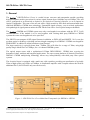
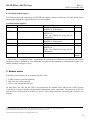
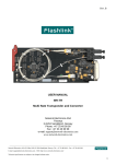
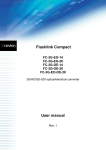
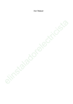
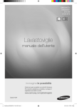
Flashlink User Manual
SDI-TR-D15xx/SDI-TR-C1xxx
Multi Rate Transponder and Converter
for
Wavelength Division Multiplexing
network-electronics.com
Rev. 2
SDI-TR-D15xx / SDI-TR-C1xxx
Rev. 2
DATE: 29 October 2007
Revision history
The latest version is always available in pdf-format on our web-site:
http://www.network-electronics.com/
Current revision of this document is the uppermost in the table below.
Revision Replaces Date
Change Description
2
1
2007-10-29
New front page and removed old logo.
1
0
2007-10-05
Added Materials Declaration and EFUP
0
A
16.03.04
First official release
15.03.04
Preliminary version
A
Network Electronics ASA, P.O.Box 1020, N-3204 Sandefjord, Norway. Tel.: +47 33 48 99 99 – Fax: +47 33 48 99 98
E-mail: [email protected] – Web: http://www.network-electronics.com/
Technical specifications are subject to be changed without notice.
2
SDI-TR-D15xx / SDI-TR-C1xxx
Rev. 2
DATE: 29 October 2007
Index
1. General......................................................................................................................................................4
2. Specifications............................................................................................................................................6
3. Format Configuration .............................................................................................................................8
3.1 Configuration Examples ......................................................................................................................9
4. Connector module..................................................................................................................................10
4.1 Mounting the connector module. .......................................................................................................10
4.2 Terminal format support....................................................................................................................11
5. Module status .........................................................................................................................................11
5.1 GPI ALARM – Module Status Outputs ..............................................................................................12
5.2 Front Panel - Status Monitoring .......................................................................................................13
6. Laser safety precautions........................................................................................................................14
Declaration of conformity with CE ..........................................................................................................15
General environmental requirements for Network flashlink® equipment...........................................15
Product Warranty .....................................................................................................................................16
Materials declaration and recycling information ...................................................................................17
Materials declaration ................................................................................................................................17
Environmentally-friendly use period.......................................................................................................17
Recycling information ...............................................................................................................................18
Network Electronics ASA, P.O.Box 1020, N-3204 Sandefjord, Norway. Tel.: +47 33 48 99 99 – Fax: +47 33 48 99 98
E-mail: [email protected] – Web: http://www.network-electronics.com/
Technical specifications are subject to be changed without notice.
3
SDI-TR-D15xx / SDI-TR-C1xxx
Rev. 2
DATE: 29 October 2007
1. General
The flashlink ® SDI-TR-D15xx/-C1xxx is a multi bit-rate converter and transponder module providing
high performance media conversion for various signal formats from 19.4Mbps up to 622Mbps. The unit
can be configured as an Electrical to Optical or an Optical to Electrical converter, or as an Optical to
Optical Transponder. This state of the art unit offers a high sensitivity PIN diode and narrowband ultrastabilised DWDM or CWDM laser technology. Unmatched signal accuracy, even in critical applications
with pathological signal patterns makes the SDI-TR the first choice for all optical transport demands.
The flashlink ® DWDM and CWDM system uses only wavelengths in accordance with the ITU-T G.692
recommendation. If the module is to be used together with existing third party DWDM or CWDM
systems the exact wavelength needs to be specified.
The SDI-TR can transport all SD signal formats in addition to DVB-ASI and SMPTE 310. It can also
perform optical refreshing, reclocking and wavelength swapping for a DWDM / CWDM wavelength for
SDH/SONET in addition to all the broadcast signal formats.
The input sensitivity is typically better than –30dBm. This will allow for a range of 70km, using high
quality Single Mode fiber at 270Mbps, for a 16 channel DWDM system.
The optical output comes with a sophisticated 1550nm DFB DWDM / CWDM laser covering the
demands of short, medium and long haul applications. The open system platform of Network Electronics
DWDM / CWDM multiplexing technology allows easy interoperability with third party fiber optical
systems.
The electrical input is equipped with a multi rate cable equaliser providing an equalisation of typically
250m of high quality coax cable at 270Mbps. A distribution amplifier with 2 outputs reduces the need for
additional DA’s (for DVB-ASI only one can be used).
Figure 1 - SDI-TR-D15xx/-C1xxx Multi Rate Transponder for DWDM or CWDM
Network Electronics ASA, P.O.Box 1020, N-3204 Sandefjord, Norway. Tel.: +47 33 48 99 99 – Fax: +47 33 48 99 98
E-mail: [email protected] – Web: http://www.network-electronics.com/
Technical specifications are subject to be changed without notice.
4
SDI-TR-D15xx / SDI-TR-C1xxx
Rev. 2
DATE: 29 October 2007
SDI-TR-D15xx is available in 32 versions:
Part number
SDI-TR -D1549.32
SDI-TR -D1552.52
SDI-TR -D1555.75
SDI-TR -D1558.98
SDI-TR -D1530.33
SDI-TR -D1533.47
SDI-TR -D1536.61
SDI-TR -D1539.77
Wavelength
1549.32nm laser
1552.52nm laser
1555.75nm laser
1558.98nm laser
1530.33nm laser
1533.47nm laser
1536.61nm laser
1539.77nm laser
Part number
SDI-TR -D1550.92
SDI-TR -D1554.13
SDI-TR -D1557.36
SDI-TR -D1560.61
SDI-TR -D1531.90
SDI-TR -D1535.04
SDI-TR -D1538.19
SDI-TR -D1541.35
Wavelength
1550.92nm laser
1554.13nm laser
1557.36nm laser
1560.61nm laser
1531.90nm laser
1535.04nm laser
1538.19nm laser
1541.35nm laser
SDI-TR -D1531.12
SDI-TR -D1534.25
SDI-TR -D1537.40
SDI-TR -D1540.56
SDI-TR -D1548.51
SDI-TR -D1551.72
SDI-TR -D1554.94
SDI-TR -D1558.17
1531.12nm laser
1534.25nm laser
1537.40nm laser
1540.56nm laser
1548.51nm laser
1551.72nm laser
1554.94nm laser
1558.17nm laser
SDI-TR -D1532.68
SDI-TR -D1535.82
SDI-TR -D1538.98
SDI-TR -D1542.14
SDI-TR -D1550.12
SDI-TR -D1553.33
SDI-TR -D1556.55
SDI-TR -D1559.79
1532.68nm laser
1535.82nm laser
1538.98nm laser
1542.14nm laser
1550.12nm laser
1553.33nm laser
1556.55nm laser
1559.79nm laser
Optionally all wavelengths in the ITU-T G.692 recommendation are available on request.
SDI-TR-C1xxx is available in 8 versions:
Part number
SDI-TR –C1470
SDI-TR –C1490
SDI-TR –C1510
SDI-TR –C1530
Wavelength
1470nm laser
1490nm laser
1510nm laser
1530nm laser
Part number
SDI-TR –C1550
SDI-TR –C1570
SDI-TR –C1590
SDI-TR –C1610
Wavelength
1550nm laser
1570nm laser
1590nm laser
1610nm laser
Network Electronics ASA, P.O.Box 1020, N-3204 Sandefjord, Norway. Tel.: +47 33 48 99 99 – Fax: +47 33 48 99 98
E-mail: [email protected] – Web: http://www.network-electronics.com/
Technical specifications are subject to be changed without notice.
5
SDI-TR-D15xx / SDI-TR-C1xxx
Rev. 2
DATE: 29 October 2007
2. Specifications
Optical Input
Data rate optical:
Sensitivity:
for SDI (270Mbps)
for SDH / SONET (622Mbps)
Detector overload threshold:
Optical wavelength:
Transmission circuit fiber:
Connector return loss:
Detector damage threshold:
Connector
Optical Output
Transmission circuit fiber:
Light source:
Optical power:
Extinction Ratio:
Optical centre wavelength:
Max. wavelength drift:
for DWDM:
for CWDM:
Jitter (UI=Unit Interval):
Connector return loss:
Maximum reflected power:
Connector:
Electrical
Power:
Control:
19.4 to 622 Mbps
better than –30dBm
better than –28dBm
min. -6dBm
2nd & 3rd opt. window
1310nm & 1550nm
Multi Mode 50/125um, Single Mode Compatible
>40dB w/SM fiber
>+1dBm
SC/UPC
Single Mode
DFB Laser
0dBm, ± 1dB
≥ 10:1
According to
ITU-T G.692 for DWDM
ITU-T G.694.2 for CWDM
± 0.16nm @ temp. range: 0 to +40 °C
± 6nm @ temp. range: 0 to +40 °C
0.135 UI max. @ 270Mbps
>40dB w/SM fiber
4%
SC/UPC
+5V DC / 10W Max.
5W typically
Control system for access to setup and module status
with BITE (Built-In Test Equipment)
Network Electronics ASA, P.O.Box 1020, N-3204 Sandefjord, Norway. Tel.: +47 33 48 99 99 – Fax: +47 33 48 99 98
E-mail: [email protected] – Web: http://www.network-electronics.com/
Technical specifications are subject to be changed without notice.
6
SDI-TR-D15xx / SDI-TR-C1xxx
Electrical Input
Data rate NRZ:
Equalisation:
Impedance:
Return loss:
Signal level:
Connector:
Electrical Output
Number of outputs:
Connector:
Impedance:
Return loss:
Jitter:
Peak to peak signal level:
Signal polarity
Rev. 2
DATE: 29 October 2007
19.4 to 540 Mbps
Automatic
Cable equaliser and reclocker can be bypassed to
support bitrates down to 2Mbps.
75 ohm
>15dB @ 270MHz
nom. 800mV
BNC
2
BNC
75 ohm
>15dB @ 270MHz
max 0.2UI
0.8V ± 0.1V
1 non inverting,
1 inverting
Standards
Supported standards for electrical and optical ports:
SMPTE:
SMPTE259M, SMPTE297, SMPTE305M,
SMPTE310,
DVB-ASI:
EN50083-9
ITU-T:
G.694.1, G.694.2
Additional supported standards for the optical ports, only optical transponder configuration:
SDH / SONET:
STM1 / OC3
STM4 / OC12
Network Electronics ASA, P.O.Box 1020, N-3204 Sandefjord, Norway. Tel.: +47 33 48 99 99 – Fax: +47 33 48 99 98
E-mail: [email protected] – Web: http://www.network-electronics.com/
Technical specifications are subject to be changed without notice.
7
SDI-TR-D15xx / SDI-TR-C1xxx
Rev. 2
DATE: 29 October 2007
3. Format Configuration
The SDI-TR can support a number of different formats. The correct configuration can either be set with a
DIP switch or with the GYDA Control System. The layout of SDI-TR is shown in the drawing below
with the DIP switch to the upper left position.
Figure 2 - SDI-TR-D15xx/-C1xxx board layout.
DIP switch configuration must be set according to the table below:
Switch #
1
2
3
4
5
Label
6
GBE
7
622
8
OVR
D/B
E/O
RCL
EQ
ASI
Function DIP=ON
Broadcast format support
Optical input selected
Reclocker ON
Cable equaliser ON
DVB-ASI Reclocker
support
Not used
STM-4 / OC-12
Reclocking (622Mbps)
Override GYDA control
Config. with DIP switch
Function DIP=OFF
Datacom format support
Electrical input selected
Reclocker Bypass
Cable equaliser Bypass
SDI 177Mbps Reclocker
support
SDH/SONET
Reclocking Selected
STM-1 / OC-3 (optical)
Reclocking (155Mbps)
GYDA control
Config. with GYDA
Comment
Format mode
Transponder mode
Reclocker mode
Equaliser mode
Only when Broadcast
format support selected
Only when Datacom
format support selected
Only when Datacom
format support selected
Select configuration from
GYDA
All DIP switches are off when pointing towards the release handle.
When a “Broadcast format support” is selected, all clock rates for SDI and DVB-ASI are automatically
configured by the module itself.
Network Electronics ASA, P.O.Box 1020, N-3204 Sandefjord, Norway. Tel.: +47 33 48 99 99 – Fax: +47 33 48 99 98
E-mail: [email protected] – Web: http://www.network-electronics.com/
Technical specifications are subject to be changed without notice.
8
SDI-TR-D15xx / SDI-TR-C1xxx
Rev. 2
DATE: 29 October 2007
3.1 Configuration Examples
Typical configurations for SDI-TR:
Figure 3 – SDI and DVB-ASI Electrical to Optical Converter
Figure 4 – SDI and DVB-ASI Optical to Electrical Converter and Optical to Optical Transponder
Figure 5 - SDH/SONET - STM-4/OC-12 Optical to Optical Transponder
Network Electronics ASA, P.O.Box 1020, N-3204 Sandefjord, Norway. Tel.: +47 33 48 99 99 – Fax: +47 33 48 99 98
E-mail: [email protected] – Web: http://www.network-electronics.com/
Technical specifications are subject to be changed without notice.
9
SDI-TR-D15xx / SDI-TR-C1xxx
Rev. 2
DATE: 29 October 2007
4. Connector module
The SDI-TR-D15xx/-C1xxx has a dedicated connector module: MR-TR-C1. This module is mounted at
the rear of the sub-rack. The module is shown in figure 7.
Figure 7 - Overview of the MR-TR-C1 connector module
In typical use a SDI-TR / SDI-TR-D15xx / SDI-TR-C1xxx module at each end will be used. The
electrical input signal is connected to the INPUT BNC on the transmitting MT-TR, and the electrical
output is connected to the OUTPUT 1 or OUTPUT 2 BNC on the receiving SDI-TR. Please note that
OUTPUT 2 has an inverted signal, so formats like DVB-ASI can not use be used on this output.
4.1 Mounting the connector module.
The details of how the connector module is mounted, is found in the user manual for the sub-rack frame
FR-2RU-10-2.
This manual is also available from our web site: http://www.network-electronics.com/
Network Electronics ASA, P.O.Box 1020, N-3204 Sandefjord, Norway. Tel.: +47 33 48 99 99 – Fax: +47 33 48 99 98
E-mail: [email protected] – Web: http://www.network-electronics.com/
Technical specifications are subject to be changed without notice.
10
SDI-TR-D15xx / SDI-TR-C1xxx
Rev. 2
DATE: 29 October 2007
4.2 Terminal format support
The different input and output ports on SDI-TR can support a number of formats. The table below shows
which signal formats are supported on the selected terminals.
Terminal format support:
Terminal
Function
INPUT
Electrical Input
Supported Format
SDI, DVB-ASI,
SMPTE310, Transparent*
OPT RX
Optical Input (Receiver)
SDI, DVB-ASI,
SMPTE310,
STM-1 opt., STM-4, OC-3 opt., OC-12,
Transparent*
OUTPUT 1
Electrical Output – None inverted SDI, DVB-ASI,
SMPTE310, Transparent*
OUTPUT 2
Electrical Output – Inverted
SDI, Transparent*
OPT TX
Optical Output (Transmitter)
SDI, DVB-ASI,
SMPTE310,
STM-1 opt., STM-4, OC-3 opt., OC-12,
Transparent*
GPI ALARM Open Collector Alarms
Wired alarms
Mode
Input
Input
Output
Output
Output
OC
Output
* SDI-TR has a “Transparent mode”. In this mode all reclockers and CDR’s are switched off and no jitter
attenuation will be performed. This mode may be used for non-standard or unsupported bit rates over
shorter distances and up to 1 Gbps.
5. Module status
The status of the module can be monitored in three ways.
1. GYDA System Controller (optional).
2. GPI at the rear of the sub-rack.
3. LED’s at the front of the sub-rack.
Of these three, the GPI and the LED’s are mounted on the module itself, whereas the GYDA System
Controller is a separate module giving detailed information on the card status. The functions of the GPI
and the LED’s are described in sections 5.1 and 5.2. The GYDA controller is described in a separate user
manual.
Network Electronics ASA, P.O.Box 1020, N-3204 Sandefjord, Norway. Tel.: +47 33 48 99 99 – Fax: +47 33 48 99 98
E-mail: [email protected] – Web: http://www.network-electronics.com/
Technical specifications are subject to be changed without notice.
11
SDI-TR-D15xx / SDI-TR-C1xxx
Rev. 2
DATE: 29 October 2007
5.1 GPI ALARM – Module Status Outputs
These outputs can be used for wiring up alarms for third party control systems. The GPI outputs are open
collector outputs, sinking to ground when an alarm is triggered. The GPI connector is shown in figure 8.
Electrical Maximums for GPI outputs
Max current: 100mA
Max voltage: 30V
SDI-TR module GPI pinning:
Signal
Name
Status
General error status for the module.
Laser Fail Laser Fail Alarm
LOS
Los Of Signal
LOCK
Reclocker in Lock
Ground
0 volt pin
Pin #
Pin 1
Pin 2
Pin 3
Pin 4
Pin 8
Mode
Open Collector
Open Collector
Open Collector
Open Collector
0V.
Figure 8 - GPI Outlet
Network Electronics ASA, P.O.Box 1020, N-3204 Sandefjord, Norway. Tel.: +47 33 48 99 99 – Fax: +47 33 48 99 98
E-mail: [email protected] – Web: http://www.network-electronics.com/
Technical specifications are subject to be changed without notice.
12
SDI-TR-D15xx / SDI-TR-C1xxx
Rev. 2
DATE: 29 October 2007
5.2 Front Panel - Status Monitoring
The status of the module can be easily monitored visually by the LED’s at the front of the module. The
LED’s are visible through the front panel as shown in figure 9 below.
(Text not printed on the front panel).
Figure 9 - Front panel indicator overview for SDI-TR-D15xx and SDI-TR-13T/15T
The SDI-TR has 4 LED’s each showing a status corresponding to the GPI pinning. The position of the
different LED’s is shown in figure 9.
Diode \ state
Status
Laser fail
LOS
LOCK
Red LED
Module is faulty
Green LED
Module is OK
Module power is OK
Laser is malfunctioning and Laser is OK
the APC can no longer
keep the output power
within range.
Loss of signal
Optical input signal
No optical input signal.
Present
Re-clocker is out of lock
Re-clocker is in lock on
a supported signal
format
No light
Module has no
power
Network Electronics ASA, P.O.Box 1020, N-3204 Sandefjord, Norway. Tel.: +47 33 48 99 99 – Fax: +47 33 48 99 98
E-mail: [email protected] – Web: http://www.network-electronics.com/
Technical specifications are subject to be changed without notice.
13
SDI-TR-D15xx / SDI-TR-C1xxx
Rev. 2
DATE: 29 October 2007
6. Laser safety precautions
Guidelines to limit hazards from laser exposure.
All the available EO units in the flashlink® range include a laser.
Therefore this note on laser safety should be read thoroughly.
The lasers emit light at wavelengths around 1310 nm or 1550 nm. This means that the human eye cannot
see the beam, and the blink reflex can not protect the eye. (The human eye can see light between 400 nm
to 700 nm).
A laser beam can be harmful to the human eye (depending on laser power and exposure time). Therefore:
!! BE CAREFUL WHEN CONNECTING / DISCONNECTING FIBER PIGTAILS (ENDS).
NEVER LOOK DIRECTLY INTO THE PIGTAIL OF THE LASER/FIBER.
NEVER USE MICROSCOPES, MAGNIFYING GLASSES OR EYE LOUPES TO LOOK INTO A
FIBER END.
USE LASER SAFETY GOGGLES BLOCKING LIGHT AT 1310 nm AND AT 1550 nm
Instruments exist to verify light output power: Power meters, IR-cards etc.
flashlink® features:
All the laser module cards in the flashlink® product range, are Class 1 laser products according to
IEC 825-1 1993, and class I according to 21 CFR 1040.10 when used in normal operation.
More details can be found in the user manual for the FR-2RU-10-2 frame.
Maximum output power*: 5 mW.
Operating wavelengths: > 1270 nm.
*
Max power is for safety analysis only and does not represent device performance.
Network Electronics ASA, P.O.Box 1020, N-3204 Sandefjord, Norway. Tel.: +47 33 48 99 99 – Fax: +47 33 48 99 98
E-mail: [email protected] – Web: http://www.network-electronics.com/
Technical specifications are subject to be changed without notice.
14
SDI-TR-D15xx / SDI-TR-C1xxx
Rev. 2
DATE: 29 October 2007
Declaration of conformity with CE
This apparatus meets the requirements of EN 55103-1 (November 1996) with regard to emissions, and
EN 55103-2 (November 1996) with regard to immunity; it thereby complies with the Electromagnetic
Compatibility Directive 89/336/EEC.
General environmental requirements for Network flashlink® equipment
1. The equipment will meet the guaranteed performance specification under the following environmental
conditions:
•
•
Operating room temperature range
Operating relative humidity range
0°C to 40°C
up to 90% (non-condensing)
2. The equipment will operate without damage under the following environmental conditions:
•
•
Temperature range
Relative humidity range
-10°C to 50°C
up to 95% (non-condensing)
3. Electromagnetic compatibility conditions:
•
•
Emissions
Immunity
EN 55103-1
EN 55103-2
(Directive 89/336/EEC)
(Directive 89/336/EEC)
Network Electronics ASA, P.O.Box 1020, N-3204 Sandefjord, Norway. Tel.: +47 33 48 99 99 – Fax: +47 33 48 99 98
E-mail: [email protected] – Web: http://www.network-electronics.com/
Technical specifications are subject to be changed without notice.
15
SDI-TR-D15xx / SDI-TR-C1xxx
Rev. 2
DATE: 29 October 2007
Product Warranty
The warranty terms and conditions for the product(s) covered by this manual follow the General Sales
Conditions by Network Electronics ASA. These conditions are available on the company web site of
Network Electronics ASA:
www.network-electronics.com
Network Electronics ASA, P.O.Box 1020, N-3204 Sandefjord, Norway. Tel.: +47 33 48 99 99 – Fax: +47 33 48 99 98
E-mail: [email protected] – Web: http://www.network-electronics.com/
Technical specifications are subject to be changed without notice.
16
SDI-TR-D15xx / SDI-TR-C1xxx
Rev. 2
DATE: 29 October 2007
Materials declaration and recycling information
Materials declaration
For product sold into China after 1st March 2007, we comply with the “Administrative Measure on the
Control of Pollution by Electronic Information Products”. In the first stage of this legislation, content of
six hazardous materials has to be declared. The table below shows the required information.
Toxic or hazardous substances and elements
組成名稱
Part Name
SDI-TR-D15xx /
SDI-TR-C1xx
鉛
汞
镉
六价铬
多溴联苯
多溴二苯醚
Lead Mercury Cadmium Hexavalen Polybrominate Polybrominate
(Pb)
(Hg)
(Cd)
t
d biphenyls
d diphenyl
Chromium
(PBB)
ethers
(Cr(VI))
(PBDE)
X
O
O
O
O
O
O: Indicates that this toxic or hazardous substance contained in all of the homogeneous materials for
this part is below the limit requirement in SJ/T11363-2006.
X: Indicates that this toxic or hazardous substance contained in at least one of the homogeneous
materials used for this part is above the limit requirement in SJ/T11363-2006.
Environmentally-friendly use period
The manual must include a statement of the “environmentally friendly use period”. This is defined as the
period of normal use before any hazardous material is released to the environment. The guidance on how
the EFUP is to be calculated is not finalised at the time of writing. See
http://www.aeanet.org/GovernmentAffairs/qfLeOpAaZXaMxqGjSFbEidSdPNtpT.pdf for an unofficial
translation of the draft guidance. For our own products, Network Electronics has chosen to use the 50
year figure recommended in this draft regulation.
Network Electronics suggests the following statement on An “Environmentally Friendly Use Period”
(EFUP) setting out normal use:
EFUP is the time the product can be used in normal service life without leaking the hazardous materials. We expect the normal
use environment to be in an equipment room at controlled temperature range (0ºC - 40ºC) with moderate humidity (< 90%, noncondensing) and clean air, not subject to vibration or shock.
Further, a statement on any hazardous material content, for instance, for a product that uses some tin/lead
solders:
Where a product contains potentially hazardous materials, this is indicated on the product by the appropriate symbol containing
the EFUP. The hazardous material content is limited to lead (Pb) in some solders. This is extremely stable in normal use and the
EFUP is taken as 50 years, by comparison with the EFUP given for Digital Exchange/Switching Platform in equipment in
Appendix A of “General Rule of Environment-Friendly Use Period of Electronic Information Products”. This is indicated by the
product marking:
Network Electronics ASA, P.O.Box 1020, N-3204 Sandefjord, Norway. Tel.: +47 33 48 99 99 – Fax: +47 33 48 99 98
E-mail: [email protected] – Web: http://www.network-electronics.com/
Technical specifications are subject to be changed without notice.
17
SDI-TR-D15xx / SDI-TR-C1xxx
Rev. 2
DATE: 29 October 2007
50
It is assumed that while the product is in normal use, any batteries associated with real-time clocks or battery-backed RAM will
be replaced at the regular intervals.
The EFUP relates only to the environmental impact of the product in normal use, it does not imply that the product will
continue to be supported for 50 years.
Recycling information
Network Electronics provides assistance to customers and recyclers through our web site
http://www.network-electronics.com. Please contact Network Electronics’ Customer Support for
assistance with recycling if this site does not show the information you require.
Where it is not possible to return the product to Network Electronics or its agents for recycling, the
following general information may be of assistance:
Before attempting disassembly, ensure the product is completely disconnected from power and signal
connections.
All major parts are marked or labelled to show their material content.
Depending on the date of manufacture, this product may contain lead in solder.
Some circuit boards may contain battery-backed memory devices.
Network Electronics ASA, P.O.Box 1020, N-3204 Sandefjord, Norway. Tel.: +47 33 48 99 99 – Fax: +47 33 48 99 98
E-mail: [email protected] – Web: http://www.network-electronics.com/
Technical specifications are subject to be changed without notice.
18