1
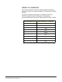
DB-25 Male Connector
DESCRIPTION
PIN
1
2
3
4
5
6
7
8
9
10
11
12
13
14
15
16
17
18
19
20
21
22
23
24
25
RELAY
RELAY
RELAY
RELAY
1
1
1
2
Common
Normally Closed
Normally Open
Common
RELAY 2 Normally Closed
RELAY 2 Normally Open
RELAY 3 Common
RELAY 3 Normally Closed
RELAY 3 Normally Open
RELAY 4 Common
RELAY 4 Normally Closed
RELAY 4 Normally Open
GROUND
RELAY 5 Common
RELAY 5 Normally Closed
RELAY 5 Normally Open
RELAY 6 Common
RELAY 6 Normally Closed
RELAY 6 Normally Open
RELAY 7 Common
RELAY 7 Normally Closed
RELAY 7 Normally Open
RELAY 8 Common
RELAY 8 Normally Closed
RELAY 8 Normally Open
Common
RELAY 1
Normally Closed
Normally Open
Common
RELAY 2
Normally Closed
Normally Open
1
14
2
15
3
16
4
17
5
18
6
19
Common
RELAY 3
Normally Closed
Normally Open
Common
RELAY 4
Normally Closed
Normally Open
7
20
8
21
9
22
10
23
11
24
12
25
Digital Ground
Common
Normally Closed
RELAY 5
Normally Open
Common
Normally Closed
RELAY 6
Normally Open
Common
Normally Closed
RELAY 7
Normally Open
Common
Normally Closed
RELAY 8
Normally Open
13
30 VDC at 1 Ampere
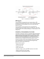
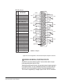
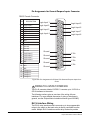
Figure 4-5: Pin Configuration of the General-Purpose Outputs Connector
5
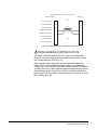
WIRING GENERAL-PURPOSE INPUTS
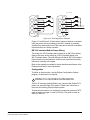
The DB-25 connector labeled “GP IN” connects the matrix to eight
local general-purpose inputs (GPIs).
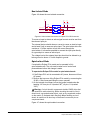
When delivered from the factory, the general purpose inputs operate in
non-isolated mode. The non-isolated mode does not require that the
externally connected equipment powers the general-purpose input.
The current is supplied by a voltage output on the “GP IN” connector.
Clear-Com Communication Systems
Eclipse PiCo Matrix Instruction Manual
4-7